ISUZU KB P190 2007 Workshop Repair Manual
KB P190 2007
ISUZU
ISUZU
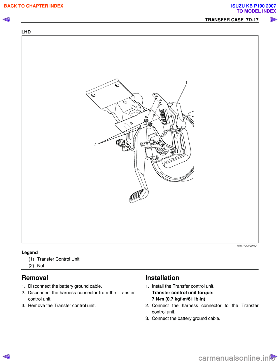
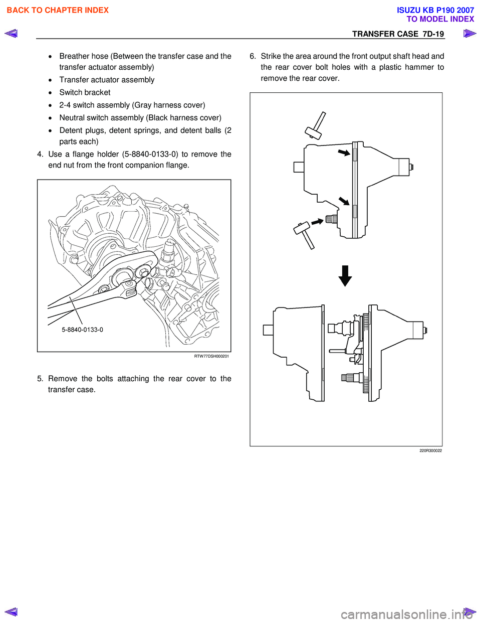
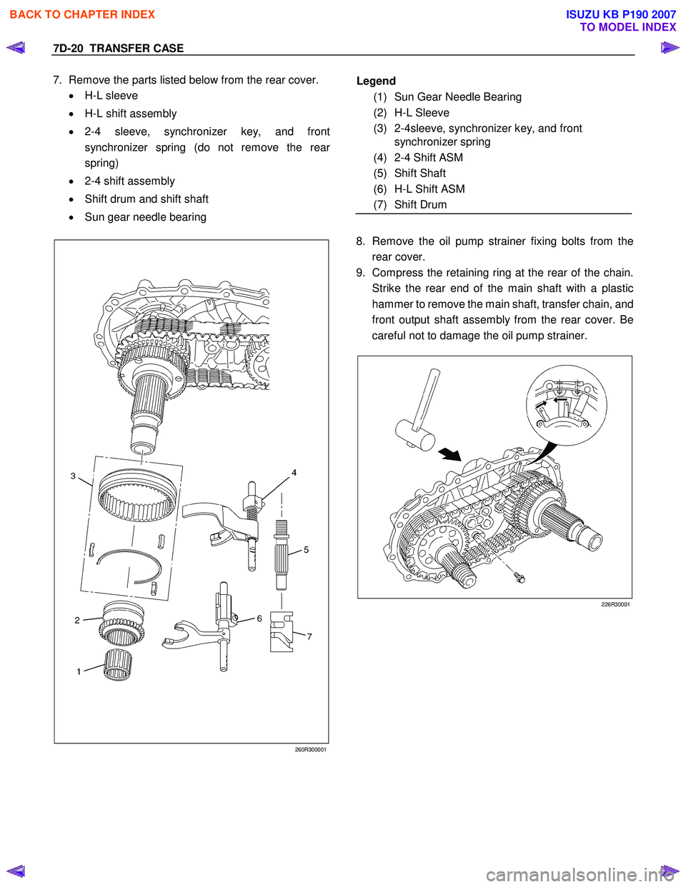
https://www.carmanualsonline.info/img/61/57177/w960_57177-0.png
ISUZU KB P190 2007 Workshop Repair Manual
Trending: check 4wd, engine mount, pairing phone, ECO mode, transmission oil, differential, clock
Page 4841 of 6020
TRANSFER CASE 7D-11
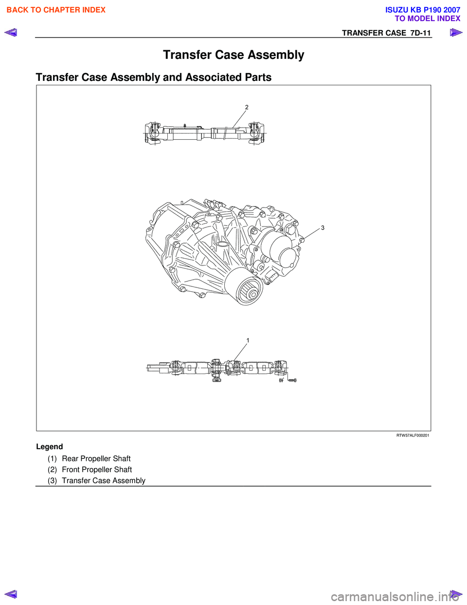
Transfer Case Assembly
Transfer Case Assembly and Associated Parts
RTW 57ALF000201
Legend
(1) Rear Propeller Shaft
(2) Front Propeller Shaft
(3) Transfer Case Assembly
BACK TO CHAPTER INDEX
TO MODEL INDEX
ISUZU KB P190 2007
Page 4842 of 6020

7D-12 TRANSFER CASE
Removal
NOTE: Before removing transmission and transfer
assembly from vehicle, change the transfer mode to
2W D using the 4W D push button switch on dash panel.
1. Disconnect battery ground cable.
2. Raise and support vehicle with suitable stands. Drain
transfer case fluid.
3. Remove rear propeller shaft and front propeller shaft.
NOTE: Apply alignment marks on the flange at both front
and rear sides.
4. Disconnect harness connectors and clip.
Connector: transfer switch, 2W D-4W D actuator,
speed sensor.
NOTE: Avoid turning the vehicle ignition switch to the ON
position when the 2W D-4W D connector is removed
(battery connected).
If the ignition switch must be turned to the ON position,
the controller must first be removed (memory must be
cleared because the CHECK 4W D INDICATOR will
light).
5. Remove transfer case assembly from the vehicle.
Installation
1. Apply a thin coat of molybdenum disulfide grease to
the input shaft spline as shown in the figure.
260R300001
BACK TO CHAPTER INDEX
TO MODEL INDEX
ISUZU KB P190 2007
Page 4843 of 6020
TRANSFER CASE 7D-13
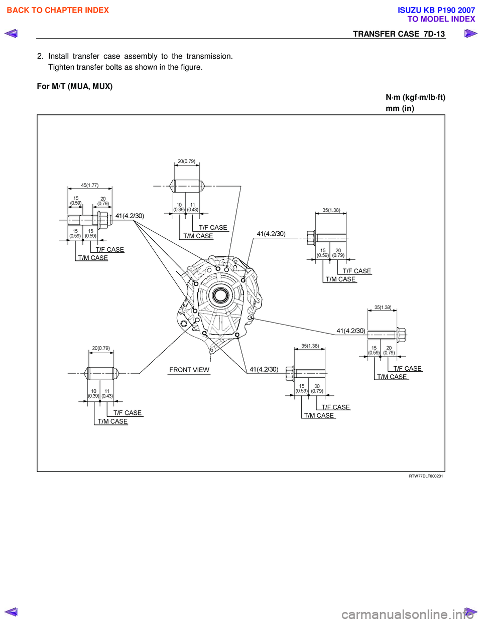
2. Install transfer case assembly to the transmission.
Tighten transfer bolts as shown in the figure.
For M/T (MUA, MUX)
N⋅
⋅⋅
⋅
m (kgf ⋅
⋅⋅
⋅
m/lb ⋅
⋅⋅
⋅
ft)
mm (in)
RTW 77DLF000201
BACK TO CHAPTER INDEX
TO MODEL INDEX
ISUZU KB P190 2007
Page 4844 of 6020
7D-14 TRANSFER CASE
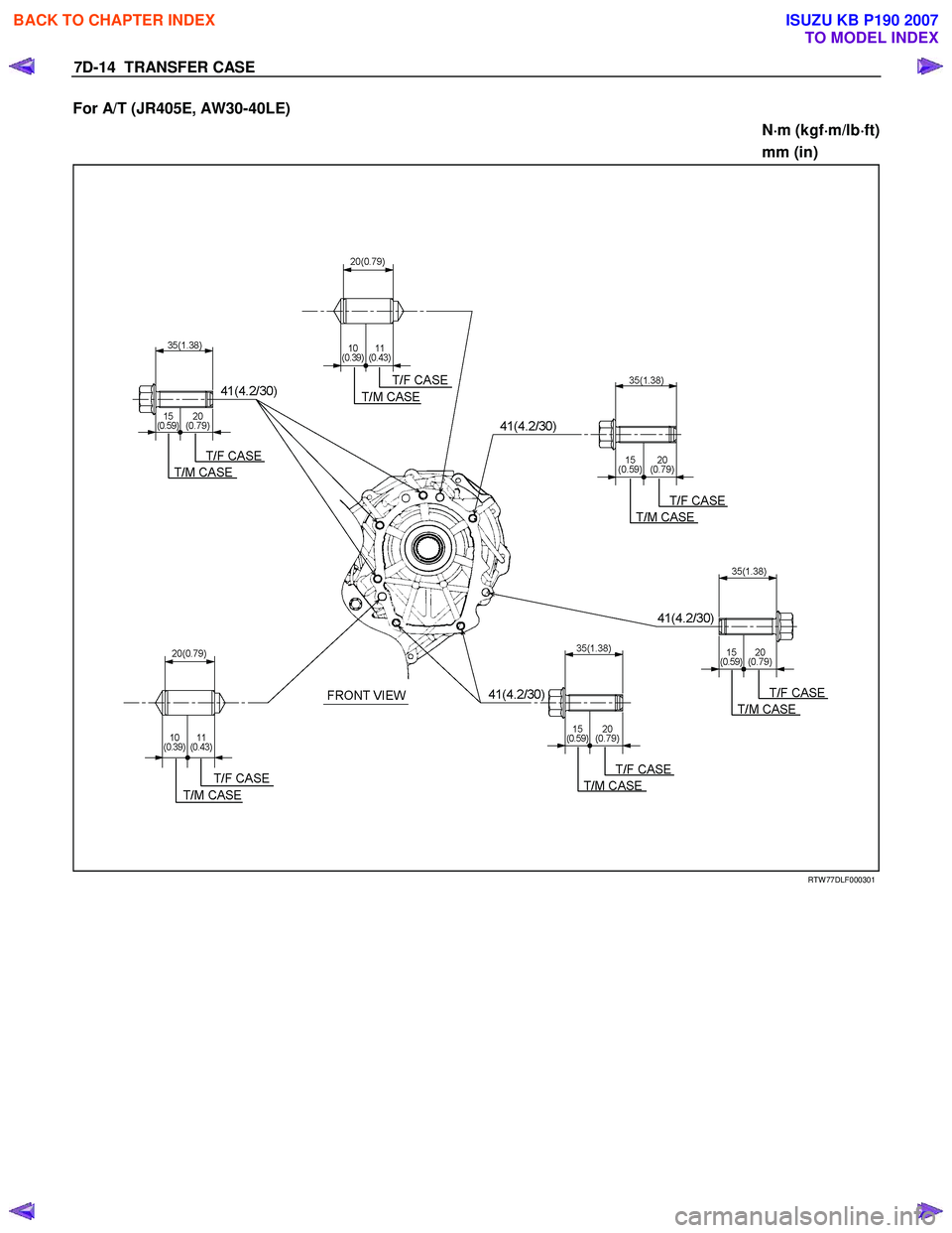
For A/T (JR405E, AW30-40LE)
N⋅
⋅⋅
⋅
m (kgf ⋅
⋅⋅
⋅
m/lb ⋅
⋅⋅
⋅
ft)
mm (in)
RTW 77DLF000301
BACK TO CHAPTER INDEX
TO MODEL INDEX
ISUZU KB P190 2007
Page 4845 of 6020
TRANSFER CASE 7D-15
For M/T (AR-5), A/T (4L60-E)
N⋅
⋅⋅
⋅
m (kgf ⋅
⋅⋅
⋅
m/lb ⋅
⋅⋅
⋅
ft)
mm (in)
RTW 77DLF000401
3. Connect harness connectors and clip.
Connector: transfer switch, 2W D-4W D actuator,
speed sensor.
4. Install rear propeller shaft and front propeller shaft.
Propeller shaft torque: 59 N ⋅
⋅⋅
⋅
m (6.0 kgf ⋅
⋅⋅
⋅
m/43 lb ⋅
⋅⋅
⋅
ft)
BACK TO CHAPTER INDEX
TO MODEL INDEX
ISUZU KB P190 2007
Page 4846 of 6020
7D-16 TRANSFER CASE
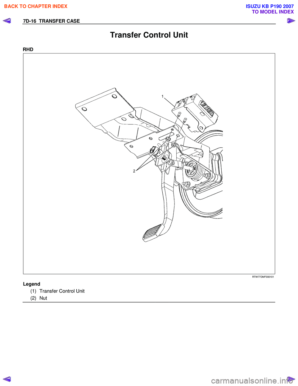
Transfer Control Unit
RHD
RTW 77DMF000101
Legend
(1) Transfer Control Unit
(2) Nut
BACK TO CHAPTER INDEX
TO MODEL INDEX
ISUZU KB P190 2007
Page 4847 of 6020
TRANSFER CASE 7D-17
LHD
RTW 77DMF000101
Legend
(1) Transfer Control Unit
(2) Nut
Removal
1. Disconnect the battery ground cable.
2. Disconnect the harness connector from the Transfe
r
control unit.
3. Remove the Transfer control unit.
Installation
1. Install the Transfer control unit.
Transfer control unit torque: 7 N ⋅
⋅⋅
⋅
m (0.7 kgf ⋅
⋅⋅
⋅
m/61 lb ⋅
⋅⋅
⋅
in)
2. Connect the harness connector to the Transfe
r
control unit.
3. Connect the battery ground cable.
BACK TO CHAPTER INDEX
TO MODEL INDEX
ISUZU KB P190 2007
Page 4848 of 6020
7D-18 TRANSFER CASE
Transfer Disassembly
RTW 67DLF000101
Legend
(1) Transfer Case Speedometer Bushing, Plate and Driven Gear
(2) Companion Flange, O-ring and Nut
(8)
(M/T: MUA, MUX, A/T: JR405E, AW 30-40LE)
(3) Stoneguard (9) Speed sensor (M/T: AR-5, A/T: 4L60-E)
(4) Detent Plug, Spring and Detent Ball (10) Transfer Actuator (Diesel Engine)
(5) 2-4 Switch ASM (11) Transfer Actuator (Gasoline Engine)
(6) Switch Bracket (12) Breather Hose
(7) Neutral Switch ASM (13) Heat Protector (Gasoline Engine)
Removal
1. Remove the stoneguard.
2. Remove the drain plug from the transfer case to drain
the oil.
3. Remove the parts listed below.
• Speedometer bushing, plate, and speedomete
r
driven gear (M/T: MUA, MUX, A/T: JR405E,
AW 30-40LE)
• Speed sensor (M/T: AR-5, A/T: 4L60-E)
BACK TO CHAPTER INDEX
TO MODEL INDEX
ISUZU KB P190 2007
Page 4849 of 6020
TRANSFER CASE 7D-19
• Breather hose (Between the transfer case and the
transfer actuator assembly)
• Transfer actuator assembly
• Switch bracket
• 2-4 switch assembly (Gray harness cover)
• Neutral switch assembly (Black harness cover)
• Detent plugs, detent springs, and detent balls (2
parts each)
4. Use a flange holder (5-8840-0133-0) to remove the
end nut from the front companion flange.
RTW 77DSH000201
5. Remove the bolts attaching the rear cover to the
transfer case.
6. Strike the area around the front output shaft head and
the rear cover bolt holes with a plastic hammer to
remove the rear cover.
220R300022
BACK TO CHAPTER INDEX
TO MODEL INDEX
ISUZU KB P190 2007
Page 4850 of 6020
7D-20 TRANSFER CASE
7. Remove the parts listed below from the rear cover.
• H-L sleeve
• H-L shift assembly
• 2-4 sleeve, synchronizer key, and front
synchronizer spring (do not remove the rear
spring)
• 2-4 shift assembly
• Shift drum and shift shaft
• Sun gear needle bearing
260R300001
8. Remove the oil pump strainer fixing bolts from the
rear cover.
9. Compress the retaining ring at the rear of the chain.
Strike the rear end of the main shaft with a plastic
hammer to remove the main shaft, transfer chain, and
front output shaft assembly from the rear cover. Be
careful not to damage the oil pump strainer.
226R30001
Legend
(1) Sun Gear Needle Bearing
(2) H-L Sleeve
(3) 2-4sleeve, synchronizer key, and front synchronizer spring
(4) 2-4 Shift ASM
(5) Shift Shaft
(6) H-L Shift ASM
(7) Shift Drum
BACK TO CHAPTER INDEX
TO MODEL INDEX
ISUZU KB P190 2007
Trending: air suspension, fuel pressure, Alternator, 4JH1, roof rack, tow, vacuum
