ISUZU KB P190 2007 Workshop Repair Manual
Manufacturer: ISUZU, Model Year: 2007, Model line: KB P190, Model: ISUZU KB P190 2007Pages: 6020, PDF Size: 70.23 MB
Page 4861 of 6020
TRANSFER CASE 7D-31
Reassembly
Transfer Reassembly
The rear cover oil seals and the rear output shaft ball
bearings cannot be reused. They must be replaced with
new ones when the transfer is reassembled.
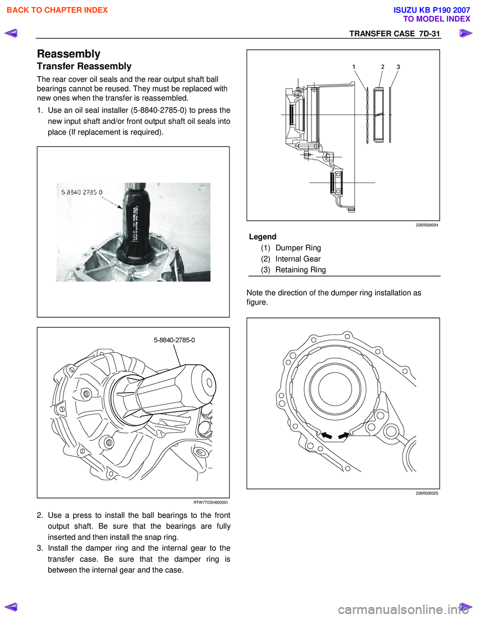
1. Use an oil seal installer (5-8840-2785-0) to press the
new input shaft and/or front output shaft oil seals into
place (If replacement is required).
RTW 77DSH000301
2. Use a press to install the ball bearings to the front
output shaft. Be sure that the bearings are full
y
inserted and then install the snap ring.
3. Install the damper ring and the internal gear to the
transfer case. Be sure that the damper ring is
between the internal gear and the case.
226R300004
Note the direction of the dumper ring installation as
figure.
226R300025
Legend
(1) Dumper Ring
(2) Internal Gear
(3) Retaining Ring
BACK TO CHAPTER INDEX
TO MODEL INDEX
ISUZU KB P190 2007
Page 4862 of 6020
7D-32 TRANSFER CASE
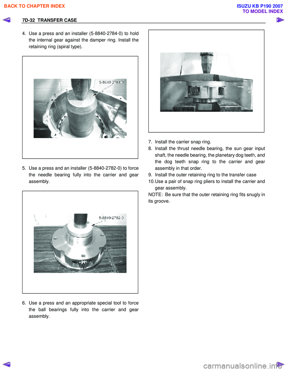
4. Use a press and an installer (5-8840-2784-0) to hold
the internal gear against the damper ring. Install the
retaining ring (spiral type).
5. Use a press and an installer (5-8840-2782-0) to force
the needle bearing fully into the carrier and gear
assembly.
6. Use a press and an appropriate special tool to force
the ball bearings fully into the carrier and gear
assembly.
7. Install the carrier snap ring.
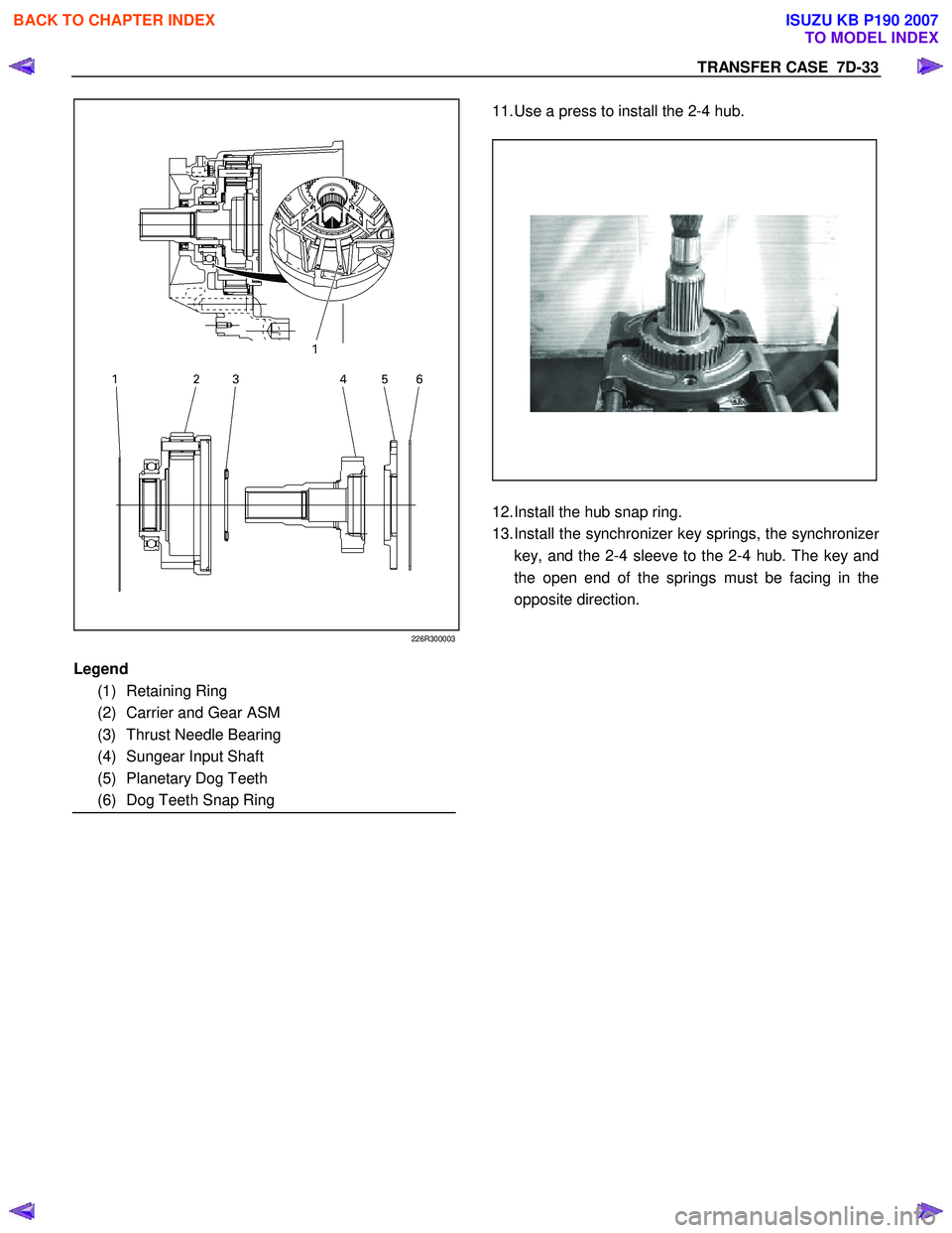
8. Install the thrust needle bearing, the sun gear input
shaft, the needle bearing, the planetary dog teeth, and
the dog teeth snap ring to the carrier and gea
r
assembly in that order.
9. Install the outer retaining ring to the transfer case
10. Use a pair of snap ring pliers to install the carrier and gear assembly.
NOTE: Be sure that the outer retaining ring fits snugly in
its groove.
BACK TO CHAPTER INDEX
TO MODEL INDEX
ISUZU KB P190 2007
Page 4863 of 6020
TRANSFER CASE 7D-33
226R300003
11. Use a press to install the 2-4 hub.
12. Install the hub snap ring.
13. Install the synchronizer key springs, the synchronize
r
key, and the 2-4 sleeve to the 2-4 hub. The key and
the open end of the springs must be facing in the
opposite direction.
Legend
(1) Retaining Ring
(2) Carrier and Gear ASM
(3) Thrust Needle Bearing
(4) Sungear Input Shaft
(5) Planetary Dog Teeth
(6) Dog Teeth Snap Ring
BACK TO CHAPTER INDEX
TO MODEL INDEX
ISUZU KB P190 2007
Page 4864 of 6020
7D-34 TRANSFER CASE
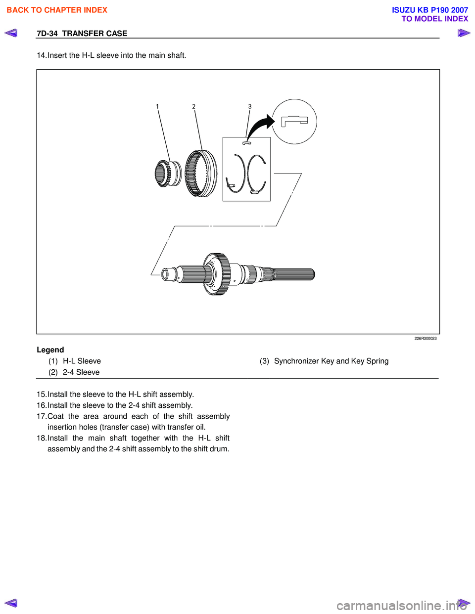
14. Insert the H-L sleeve into the main shaft.
226R300023
Legend
(1) H-L Sleeve
(3) Synchronizer Key and Key Spring
(2) 2-4 Sleeve
15. Install the sleeve to the H-L shift assembly.
16. Install the sleeve to the 2-4 shift assembly.
17. Coat the area around each of the shift assembl
y
insertion holes (transfer case) with transfer oil.
18. Install the main shaft together with the H-L shift
assembly and the 2-4 shift assembly to the shift drum.
BACK TO CHAPTER INDEX
TO MODEL INDEX
ISUZU KB P190 2007
Page 4865 of 6020
TRANSFER CASE 7D-35
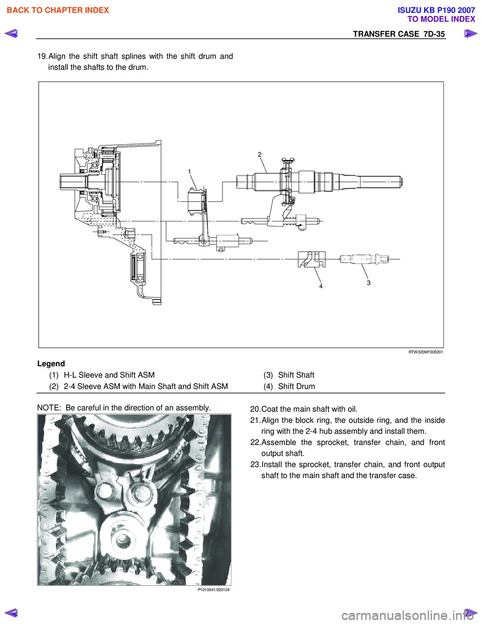
19. Align the shift shaft splines with the shift drum and
install the shafts to the drum.
RTW 320MF000201
Legend
(1) H-L Sleeve and Shift ASM
(3) Shift Shaft
(2) 2-4 Sleeve ASM with Main Shaft and Shift ASM (4) Shift Drum
NOTE: Be careful in the direction of an assembly.
P1010041/020124
20. Coat the main shaft with oil.
21.
Align the block ring, the outside ring, and the inside
ring with the 2-4 hub assembly and install them.
22. Assemble the sprocket, transfer chain, and front
output shaft.
23. Install the sprocket, transfer chain, and front output
shaft to the main shaft and the transfer case.
BACK TO CHAPTER INDEX
TO MODEL INDEX
ISUZU KB P190 2007
Page 4866 of 6020
7D-36 TRANSFER CASE
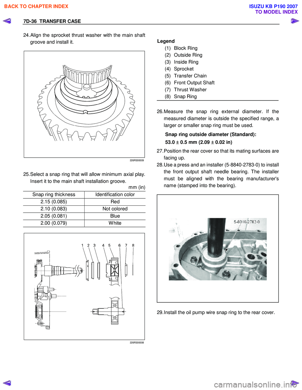
24. Align the sprocket thrust washer with the main shaft
groove and install it.
226R300009
25. Select a snap ring that will allow minimum axial play.
Insert it to the main shaft installation groove.
mm (in)
Snap ring thickness Identification color
2.15 (0.085) Red
2.10 (0.083) Not colored
2.05 (0.081) Blue
2.00 (0.079) White
226R300008
Legend
(1) Block Ring
(2) Outside Ring
(3) Inside Ring
(4) Sprocket
(5) Transfer Chain
(6) Front Output Shaft
(7) Thrust W asher
(8) Snap Ring
26. Measure the snap ring external diameter. If the
measured diameter is outside the specified range, a
larger or smaller snap ring must be used.
Snap ring outside diameter (Standard):
53.0 ±
±±
±
0.5 mm (2.09 ±
±±
±
0.02 in)
27. Position the rear cover so that its mating surfaces are
facing up.
28. Use a press and an installer (5-8840-2783-0) to install
the front output shaft needle bearing. The installe
r
must be aligned with the bearing manufacturer's
name (stamped into the bearing).
29. Install the oil pump wire snap ring to the rear cover.
BACK TO CHAPTER INDEX
TO MODEL INDEX
ISUZU KB P190 2007
Page 4867 of 6020
TRANSFER CASE 7D-37
226R300005
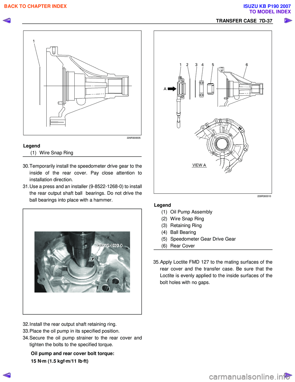
30. Temporarily install the speedometer drive gear to the
inside of the rear cover. Pay close attention to
installation direction.
31. Use a press and an installer (9-8522-1268-0) to install
the rear output shaft ball bearings. Do not drive the
ball bearings into place with a hammer.
32. Install the rear output shaft retaining ring.
33. Place the oil pump in its specified position.
34. Secure the oil pump strainer to the rear cover and
tighten the bolts to the specified torque.
Oil pump and rear cover bolt torque:
15 N ·m (1.5 kgf ·m/11 lb ·ft)
226R300010
35.
Apply Loctite FMD 127 to the mating surfaces of the
rear cover and the transfer case. Be sure that the
Loctite is evenly applied to the inside surfaces of the
bolt holes with no gaps.
Legend
(1) Oil Pump Assembly
(2) W ire Snap Ring
(3) Retaining Ring
(4) Ball Bearing
(5) Speedometer Gear Drive Gear
(6) Rear Cover
Legend
(1) W ire Snap Ring
BACK TO CHAPTER INDEX
TO MODEL INDEX
ISUZU KB P190 2007
Page 4868 of 6020
7D-38 TRANSFER CASE
226R300011
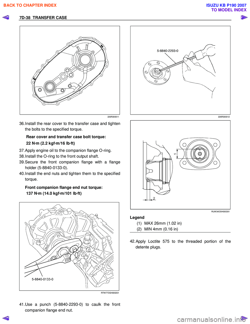
36. Install the rear cover to the transfer case and tighten
the bolts to the specified torque.
Rear cover and transfer case bolt torque:
22 N ·m (2.2 kgf ·m/16 lb ·ft)
37. Apply engine oil to the companion flange O-ring.
38. Install the O-ring to the front output shaft.
39. Secure the front companion flange with a flange
holder (5-8840-0133-0).
40. Install the end nuts and tighten them to the specified
torque.
Front companion flange end nut torque:
137 N ·m (14.0 kgf ·m/101 lb ·ft)
RTW 77DSH000201
41. Use a punch (5-8840-2293-0) to caulk the front
companion flange end nut.
226R300012
RUW 34DSH000301
Legend
(1) MAX 26mm (1.02 in)
(2) MIN 4mm (0.16 in)
42.
Apply Loctite 575 to the threaded portion of the
detente plugs.
BACK TO CHAPTER INDEX
TO MODEL INDEX
ISUZU KB P190 2007
Page 4869 of 6020
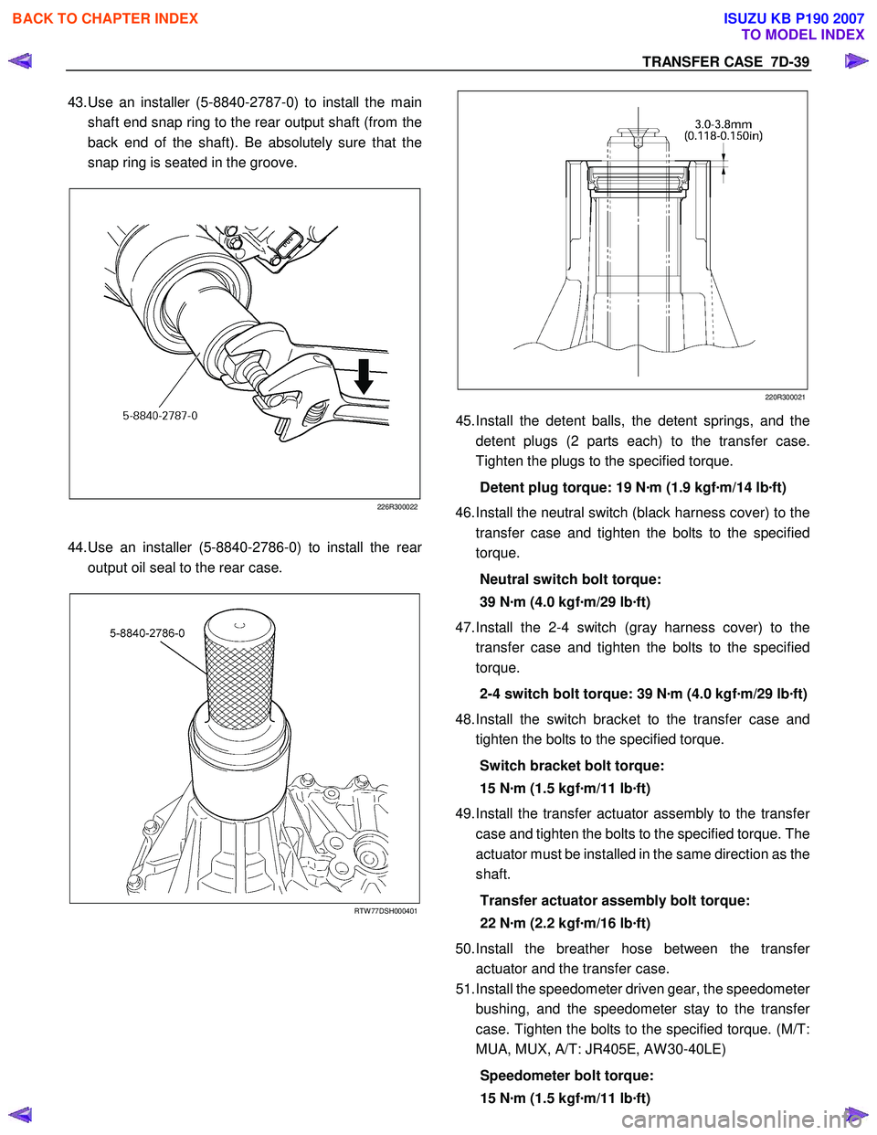
TRANSFER CASE 7D-39
43. Use an installer (5-8840-2787-0) to install the main
shaft end snap ring to the rear output shaft (from the
back end of the shaft). Be absolutely sure that the
snap ring is seated in the groove.
226R300022
44. Use an installer (5-8840-2786-0) to install the rear
output oil seal to the rear case.
RTW 77DSH000401
220R300021
45.
Install the detent balls, the detent springs, and the
detent plugs (2 parts each) to the transfer case.
Tighten the plugs to the specified torque.
Detent plug torque: 19 N ·m (1.9 kgf ·m/14 lb ·ft)
46. Install the neutral switch (black harness cover) to the
transfer case and tighten the bolts to the specified
torque.
Neutral switch bolt torque:
39 N ·m (4.0 kgf ·m/29 lb ·ft)
47. Install the 2-4 switch (gray harness cover) to the
transfer case and tighten the bolts to the specified
torque.
2-4 switch bolt torque: 39 N ·m (4.0 kgf ·m/29 lb ·ft)
48. Install the switch bracket to the transfer case and
tighten the bolts to the specified torque.
Switch bracket bolt torque:
15 N ·m (1.5 kgf ·m/11 lb ·ft)
49. Install the transfer actuator assembly to the transfe
r
case and tighten the bolts to the specified torque. The
actuator must be installed in the same direction as the
shaft.
Transfer actuator assembly bolt torque:
22 N ·m (2.2 kgf ·m/16 lb ·ft)
50. Install the breather hose between the transfe
r
actuator and the transfer case.
51. Install the speedometer driven gear, the speedomete
r
bushing, and the speedometer stay to the transfe
r
case. Tighten the bolts to the specified torque. (M/T:
MUA, MUX, A/T: JR405E, AW 30-40LE)
Speedometer bolt torque:
15 N ·m (1.5 kgf ·m/11 lb ·ft)
BACK TO CHAPTER INDEX
TO MODEL INDEX
ISUZU KB P190 2007
Page 4870 of 6020

7D-40 TRANSFER CASE
52. Install the speed sensor to the transfer case and
tighten the specified torque. (M/T: AR-5, A/T: 4L60-E)
Speed sensor torque: 17 N ·m (1.7 kgf ·m/12 lb ·ft)
53. Install the drain plug to the transfer case and tighten it
to the specified torque.
Drain plug torque: 39 N ·m (4.0 kgf ·m/29 lb ·ft)
54. Loosen and remove the filler plug. Add the specified
volume of transfer oil (5W -30) or the equivalent to the
transfer through the filler hole.
Transfer oil volume: 1.3 lit. (1.37 US qt)
55. Replace the filler plug and tighten it to the specified
torque.
Filler plug torque: 39 N ·m (4.0 kgf ·m/29 lb ·ft)
56. Install the underguard and tighten the bolts to the
specified torque.
Underguard bolt torque:
39 N ·m (4.0 kgf ·m/29 lb ·ft)
BACK TO CHAPTER INDEX
TO MODEL INDEX
ISUZU KB P190 2007