lock ISUZU TROOPER 1995 Workshop Manual
[x] Cancel search | Manufacturer: ISUZU, Model Year: 1995, Model line: TROOPER, Model: ISUZU TROOPER 1995Pages: 1928
Page 795 of 1928
DRIVEABILITV AND EMISSIONS 6E2-99
SECTION C
COMPONENTS SYSTEMS
CAUTION
When fasteners are removed, always reinstall them at the same location from which they were removed. If a
fastener needs
to be replaced, use the correct part number fastener for that application. If the correct part number
fastener is not available, a fastener of equal size and strength (or stronger) may be used. Fasteners that are not
reused, and those requiring thread locking compound will be called out. The correct torque value must be used
when installing fasteners that require it. If the above conditions are not followed, parts or system damage could
result.
Section
"C" provides information on the following:
• General description of components and sub-systems.
• On-vehicle service.
• Part names and group numbers.
• Diagnostic charts. These include a functional check of the system as well as diagnosis of any problem found in
the functional check.
For locations
of components, wiring diagrams, and engine control module terminal and view, refer to the front of
"Engine Components/Wiring Diagrams/Diagnostic Charts", Section "A".
Refer to the following sections for the appropriate sub-system information:
• C1 Engine Control Module (ECM) and Sensors ................................. Page 6E2-1 00
•
C2 Fuel Metering System .................................................. Page 6E2-116
• C3 Evaporative Emission (EVAP) Control System ............................... Page 6E2-134
• C4 Electronic Ignition (EI) System/Ignition Control (IC) ........................... Page 6E2-138
• C5 Knock Sensor (KS) System .............................................. Page 6E2-146
• C7 Exhaust Gas Recirculation (EGR) System ................................... Page 6E2-151
• C8 Shift Indicator Light (M/T Only) ........................................... Page 6E2-157
• C1 0 Air Conditioning (A/C) Compressor Clutch Control System ..................... Page 6E2-161
• C13 Positive Crankcase Ventilation (PCV) ....................................... Page 6E2-164
DIAGNOSTIC CHARTS
The following diagnostic charts can be found at the end of some of the sections.
• Chart C-1A Park/neutral Position (PNP) Switch Diagnosis (Auto Transmission only) .... Page 6E2-108
• Chart C-1 D Manifold Absolute Pressure (MAP) Output Check ...................... Page 6E2-11 0
•
Chart C-1 E Power Steering Pressure (PSP) Switch Diagnosis ...................... Page 6E2-112
• Chart C-1 F Heated Oxygen Sensor (H02S) Heater Check ......................... Page 6E2-114
• Chart C-2A Injector Balance Test ............................................. Page 6E2-128
• Chart C-2C Idle Air Control (lAC) System Check ................................. Page 6E2-130
• Chart C-2D Induction Air Control System Check (DOHC Only) ...................... Page 6E2-132
• Chart C-3 Evaporate Emission Canister Purge Valve Check ....................... Page 6E2-136
• Chart C-4D-1 Electronic Ignition (EI) Misfire at Idle ................................ Page 6E2-142
• Chart C-4D-2 Electronic Ignition (EI) Misfire Under Load ............................ Page 6E2-144
• Chart C-5 Knock Sensor (KS) System Check .................................. Page 6E2-148
• Chart C-7A Exhaust Gas Recirculation (EGR) System Check ....................... Page 6E2-154
• Chart C-8 Manual Transmission (MIT) Shift Light Check ......................... Page 6E2-158
• Chart C-1 0 Air Conditioning (A/C) System Functional Check ....................... Page 6E2-162
Page 797 of 1928
will not light when connected to the circuit. In some
cases, even an ordinary shop voltmeter
will not give an
accurate reading because its resistance is
too low.
Therefore, a 10 megohms input impedance digital
voltmeter is required to assure accurate voltage
readings.
The Engine
Control Module (ECM) controls output
circuits such as the fuel injectors, idle air control valve,
air conditioning clutch relay, etc. by controlling the
ground circuit through transistors
or a device called a
"quad-driver".
INFORMATION SENSORS
Engine Coolant Temperature (ECT) Sensor
(Fig. 6E2-51)
The Engine Coolant Temperature (ECT) Sensor is a
thermistor
(a resistor which changes value based on
temperature) mounted in the engine coolant stream.
Low ECT produces a high resistance (1 00,000 ohms at
-40.C/-40.F) while high temperature causes low
resistance (70 ohms at 130.C/266.F).
The ECM supplies a 5-volts signal to the ECT sensor
through a resistor in the
ECM and measures the
voltage. The voltage
will be high when the engine is
cold, and low when the engine is hot.
By measuring the voltage, the
ECM knows the ETC.
ECT affects most systems the ECM controls.
A failure in the
ECT sensor circuit should set a
Diagnostic Trouble Code
(DTC) 14. Remember, these
DTC(s) indicate a failure in the
ETC circuit, so proper
use
of the chart will lead to either repairing a wiring
problem or replacing the sensor, to properly repair a
problem.
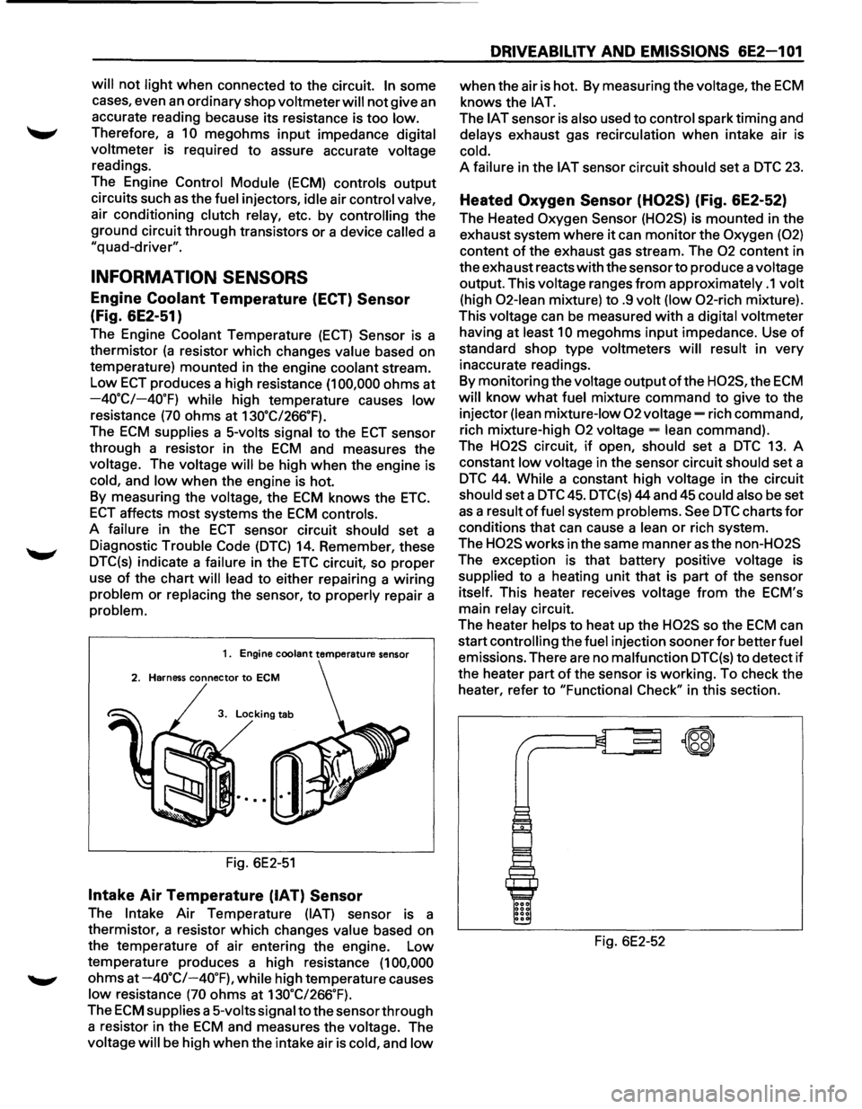
1. Engine coolant temperature sensor
2. Harness connector to ECM
3. Locking tab
Fig. 6E2-51
Intake Air Temperature (IAT) Sensor
The Intake Air Temperature (IAT) sensor is a
thermistor, a resistor which changes
value based on
the temperature
of air entering the engine. Low
temperature produces a high resistance
(1 00,000
ohms at -4o·c/-40.F), while high temperature causes
low resistance (70 ohms at 130.C/266.F).
The ECM supplies a 5-volts signal to the sensor through
a resistor in the
ECM and measures the voltage. The
voltage
will be high when the intake air is cold, and low
DRIVEABILITV AND EMISSIONS 6E2-1 01
when the air is hot. By measuring the voltage, the ECM
knows the lAT.
The IAT sensor is also used to control spark timing and
delays exhaust gas recirculation when intake air is
cold.
A failure in the IAT sensor circuit should set a DTC 23.
Heated Oxygen Sensor (H02S) (Fig. 6E2-52)
The Heated Oxygen Sensor (H02S) is mounted in the
exhaust system where
it can monitor the Oxygen (02)
content of the exhaust gas stream. The 02 content in
the exhaust reacts
with the sensor to produce a voltage
output. This voltage ranges
from approximately .1 volt
(high 02-lean mixture) to .9 volt (low 02-rich mixture).
This voltage can
be measured with a digital voltmeter
having at
least 10 megohms input impedance. Use of
standard shop type voltmeters will result in very
inaccurate readings.
By monitoring the voltage
output ofthe H02S, the ECM
will know what fuel mixture command to give to the
injector
(lean mixture-low 02 voltage= rich command,
rich mixture-high
02 voltage= lean command).
The
H02S circuit, if open, should set a DTC 13. A
constant
low voltage in the sensor circuit should set a
DTC 44. While a constant high voltage in the circuit
should set a DTC 45. DTC(s) 44 and 45 could also be set
as a result of fuel system problems. See DTC charts for
conditions that can cause a lean or rich system.
The
H02S works in the same manner as the non-H02S
The exception is that battery positive voltage is
supplied to a heating unit that is part of the sensor
itself. This heater receives voltage
from the ECM's
main
relay circuit.
The heater
helps to heat up the H02S so the ECM can
start
controlling the fuel injection sooner for better fuel
emissions. There are no malfunction DTC(s) to detect if
the heater part of the sensor is working. To check the
heater, refer to "Functional
Check" in this section.
Fig. 6E2-52
~
\W
Page 798 of 1928
6E2-1 02 DRIVEABILITV AND EMISSIONS
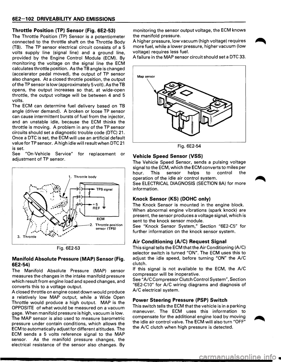
Throttle Position (TP) Sensor (Fig. 6E2-53)
The Throttle Position (TP) Sensor is a potentiometer
connected to the throttle shaft on the Throttle Body
(TB). The TP sensor electrical circuit consists of a 5
volts supply line (signal line) and a ground line,
provided by the Engine Control Module (ECM).
By
monitoring the voltage on the signal line the ECM
calculates throttle position. As the TB angle is changed
(accelerator pedal moved), the output
of TP sensor
also changes.
At a closed throttle position, the output
of the TP sensor is low (approximately 5volt). As the TB
opens, the output increases so that, at wide-open
throttle, the output voltage
will be between 4 and 5
volts.
The
ECM can determine fuel delivery based on TB
angle (driver demand). A broken or loose TP sensor
can cause intermittent bursts of fuel from the injector,
and
an unstable idle, because the ECM thinks the
throttle is moving. A problem in any
of the TP sensor
circuits should set a diagnostic trouble code
(DTC) 21.
Once a DTC is set, the ECM will use an artificial default
valueforTP sensor. A high idle will result when DTC 21
is set.
See
"On-Vehicle Service" for replacement or
adjustment
of TP sensor.
ECM
~--2. Throttle position
sensor (TPS)
Fig. 6E2-53
Manifold Absolute Pressure (MAP) Sensor (Fig.
6E2-54)
The Manifold Absolute Pressure (MAP) sensor
measures the changes in the intake manifold pressure
which result
from engine load and speed changes, and
converts this to a voltage output.
A closed throttle on engine coast
down would produce
a relatively
low MAP output, while a Wide Open
Throttle would produce a high output. MAP is the
OPPOSITE of what would be measured on a vacuum
gage. When manifold pressure is high, vacuum is low.
The
MAP sensor is also used to measure barometric
pressure under contain conditions, which
allows the
ECM to automatically adjust for different altitudes. The
ECM sends a 5 volts reference signal to the MAP
sensor. As the manifold pressure changes, the
electrical resistance
of the sensor also changes. By
monitoring the sensor output voltage, the ECM knows
the manifold pressure.
A higher pressure,
low vacuum (high voltage) requires
more fuel, while a lower pressure, higher vacuum (low
voltage) requires less
fuel.
A failure in the MAP sensor circuit should set a DTC 33.
Map sensor
Fig. 6E2-54
Vehicle Speed Sensor (VSS)
The Vehicle Speed Sensor, sends a pulsing voltage
signal to the
ECM, which the ECM converts to miles per
hour. This sensor helps to control the
operation
of the idle air control system.
See
ELECTRICAL DIAGNOSIS (SECTION 8A) for more
information.
Knock Sensor (KS) (DOHC only)
The Knock Sensor is mounted in the engine block.
When abnormal engine vibrations (spark knock) are
present, the sensor produces a voltage signal, which is
sent to the knock sensor module.
See
"Knock Sensor System," Section "6E2-C5" for
further information on the knock sensor system.
Air Conditioning (A/C) Request Signal
This signal tells the ECM that the Air Conditioning (A/C)
selector switch is turned
"ON". The ECM uses this to
adjust the idle speed, before turning
"ON" the A/C
clutch.
If this signal is not available to the ECM, the A/C
compressor will be inoperative.
See "A/C Compressor Clutch Control System", Section
"6E2-C1 0" for A/C wiring diagrams and diagnosis of
A/C electrical system.
Power Steering Pressure (PSP) Switch
This switch tells the ECM that the vehicle is in a parking
maneuver. The
ECM uses this information to
compensate
for the additional engine load by moving
the idle air control valve. The
ECM will also turn "OFF"
the A/C clutch when high pressure is detected.
•
Page 800 of 1928
6E2-1 04 DRIVEABILITV AND EMISSIONS
Engine Coolant Temperature (ECT) Sensor
A "Scan tool" displays engine temperature in degrees
centigrade. After engine is started, the temperature
should rise steadily to about 90°C then stabilize when
thermostat opens. If the engine has not been run for
several hours (overnight), the engine coolant
temperature (ECT) and intake air temperature (IAT)
readings should be close to each other. A fault in the
ECT sensor circuit should set a diagnostic trouble code
(DTC) 14. The DTC charts also contain a chart to check
for sensor resistance values relative to temperature.
Intake Air Temperature (IAT) Sensor
A "Scan tool" displays temperature of the air entering
the engine and
should read close to ambient air
temperature when engine
is cold, and rise as under
hood temperature increases.
If the engine has not
been run for several hours (overnight), the IAT sensor
temperature and
ECT readings should be close to each
other. A
failure in the IAT sensor circuit should set a
DTC 23. The DTC charts also contain a chart to check
for sensor resistance values relative to temperature.
Heated Oxygen Sensor (H02S)
The "Scan tool" has several positions that will indicate
the state
of the exhaust gases, Oxygen voltage,
integrator, and block learn. See "Scan tool" position
information in
"Introduction", "Driveability and
Emission," in this section.
A
problem in the oxygen sensor circuit, or fuel system,
should set a DTC 13 (open circuit), DTC 44 (lean
indication)/DTC 45 (rich indication). Refer to
applicable chart, if any of these DTC(s) were stored in
memory.
Throttle Position (TP) Sensor
A "Scan tool" displays throttle position in volts. On 3.2L
engine, Throttle position
(TP) sensor voltage should
read below 0.85 volts, with throttle closed and ignition
"ON", or at idle. Voltage should increase at a steady
rate
as throttle is moved toward wide open throttle.
The Engine
Control Module (ECM) has the ability to
auto-zero the TP sensor voltage if it is below about 0.85
volts. This means that any voltage less than 0.85 volts
will
be determined by the ECM to be 0% throttle.
Some
"Scan tools" have the ability to read the throttle
angle and should read 0%, when the throttle is closed.
A failure in the TP sensor or circuit should set a DTC 21.
Manifold Absolute Pressure (MAP) Sensor
"Scan tool" displays manifold pressure in volts. Low
pressure (high vacuum) reads a
low voltage, while a
high pressure
(low vacuum) reads a high voltage. A
failure in the Manifold Absolute Pressure (MAP) sensor
circuit
should set a DTC 33 and using the chart will find
the cause
of the problem. A DTC 33 may be set if a
rough or unstable
idle exists. CHART C-1 D can also be
used
to check MAP sensor.
Vehicle Speed Sensor (VSS)
A "Scan tool" reading should closely match with
speedometer reading with drive wheels turning. A
failure in the vehicle speed sensor circuit should set a
DTC 24.
AIR CONDITIONING (A/C) Request Signal
When air conditioning in "ON", the "Scan tool" should
indicate air conditioning "ON".
See
"Air Conditioning Compressor Clutch Control
System",
Section "6E2-C1 0" for A/C electrical system
diagnosis.
Power Steering Pressure (PSP) Switch
A "Scan tool" should read "OFF" normally, and "ON"
with high pressure. This reading may vary with
different "Scan tools". Refer to CHART C-1 E for power
steering pressure switch diagnosis.
Crankshaft Position (CKP) Reference Signal
The ignition control module sends a signal to the ECM,
which is used to calculate proper spark advance and
fuel delivery. A "Scan tool" will read this signal and is
displayed in revolution per minute.
See "Electronic
Ignition System",
Section "6E2-C-4" for more
information on the ignition system (ignition control).
Park/Neutral Position (PNP) Switch
A "Scan tool" should read park/neutral position when
in park, or neutral, and R-D, L, when in drive or
overdrive. This reading may vary with different makes
of tools. Refer to CHART C-1 A for park/neutral position
switch diagnosis.
Knock Sensor (KS)
A "Scan tool" will indicate when the knock sensor
module signals the ECM that knock is present. See
"Knock
Sensor System," Section "6E2-C5" for further
information on the knock sensor system.
ON-VEHICLE SERVICE
ENGINE CONTROL MODULE (ECM)
The ECM is programmed from the factory and has no replaceable calibration chip.
•
Page 817 of 1928
Throttle Position (TP) Sensor
The Throttle Position (TP) Sensor is mounted on the
side
of the throttle body opposite the throttle lever
assembly.
Its function is to sense the current throttle
body position and relay that information to the ECM.
Knowledge ofTP is needed by the ECM to generate the
proper injector pulse width.
If the TP sensor senses a
Wide
Open Throttle, a voltage signal indicating this
condition is transmitted to the
ECM. The ECM will
widen the injector pulse, or increase the repetition rate,
permitting increased fuel
flow to each for the six fuel
injectors located in the fuel fail. As the throttle shaft
rotates in response to
movement of the accelerator
pedal (opening
or closing of the throttle body), the
throttle shaft transmits throttle
movement to the TP
sensor. A potentiometer (variable resistor) within the
TP sensor assembly creates a voltage that varies in
response to
TP. By applying a reference voltage (+5
VDC) to the TP sensor input, a varying voltage
(reflecting
TP) is available at the TP sensor output. The
voltage
output from the TP sensor is sent to the ECM
for use in determining current TP.
For further information ofTP sensor, refer to "ECM and
Sensors", Section
"6E2-C1 ". The TP sensor is an auto
zeroing type and cannot
be adjusted.
DRIVEABILITY AND EMISSIONS 6E2-121
INDUCTION AIR CONTROL PLATE
SYSTEM (DOHC) (Fig. 6E2-74)
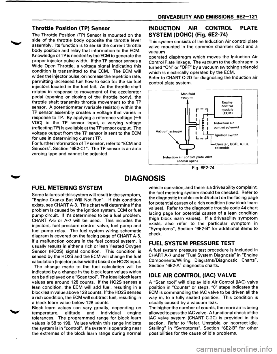
This system consists of the Induction Air control plate
valve mounted in the common chamber
duct and a
vacuum operated diaphragm
which moves the Induction Air
Control Plate linkage. The vacuum to the diaphragm is
turned
"ON" or "OFF" by a vacuum switching solenoid
which is electrically operated by the
ECM.
Refer to CHART C-20 for diagnosing the Induction air
control plate system.
Manifold vaccum
1
Vacuum actuator
Induction air control plate valve
(noma! open)
Fig. 6E2-74
Engine control module (ECM)
Ignition switch
Canister, EGR, A.I.R. solenoids
DIAGNOSIS
FUEL METERING SYSTEM
Some failures of this system will result in the symptom,
"Engine Cranks But Will Not Run". If this condition
exists, see CHART A-3. This chart will determine
if the
problem is caused by the ignition system,
ECM or fuel
pump circuit.
If it's determined to be a fuel problem.
CHART A-5
or A-7 will be used. This includes the
injectors, fuel pressure control valve, fuel
pump and
fuel pump relay. The fuel system
wiring schematic
diagram is covered on the facing page
of CHART A-5.
If a malfunction occurs in the fuel control system, it
usually results in either a rich or lean Heated Oxygen
Sensor (H02S) signal condition. This condition is
sensed by the
H02S and the ECM will change the fuel
calculation (injector pulse width) based on
H02S input.
The change made to the fuel calculation will be
indicated
by a change in the block learn values which
can be displayed on a
"Scan tool". The ideal block learn
values are around 128 counts.
If the H02S senses a
lean condition, the
ECM will add fuel, resulting in a
block learn value above 128 counts.
If the H02S senses
a rich condition, the
ECM will subtract fuel, resulting in
a block learn value below 128 counts.
Block learn values can vary greatly, depending on
temperature, altitude and individual engine
tolerances. The programmed range for block learn
values is
58 to 198. Values within this range indicate
the system is in
"control". If a system is operating near
the extremes
of the block learn range during normal vehicle
operation, and there is a driveability complaint,
the fuel metering system should be checked. Refer to
the diagnostic trouble code
45 chart on the facing page
for potential causes of a rich condition (low block learn
values). Refer to the diagnostic trouble code 44 chart
facing page
for potential causes of a lean condition
(high block learn values).
If a driveability symptom
exists, also refer to the particular symptom in
"Symptoms", Section "6E2-B" for additional items to
check.
FUEL SYSTEM PRESSURE TEST
A fuel system pressure test procedure is included in
CHART A-7 under
"Fuel System Diagnosis" in "Engine
Components/Wiring Diagrams/Diagnostic
Charts",
Section "6E2-A" diagnostic charts.
IDLE AIR CONTROL (lAC) VALVE
A "Scan tool" will display Idle Air Control (lAC) valve
position in
"Counts" or steps. "0" steps indicates the
ECM is commanding the lAC valve to be driven all the
way in, to a fully seated position. This condition is
usually caused by a vacuum leak.
The higher the number
of counts, the more air is being
allowed to pass the
lAC valve. A functional check of the
lAC valve system (CHART C-2C) is provided in this
section. Refer to
"Refer, Unstable, or Incorrect Idle,
Stalling"
in "Symptoms", Section "6E2-B" for other
possibilities
for the cause of idle problems.
Page 823 of 1928
1~1 Measure (If Installing a New Idle Air
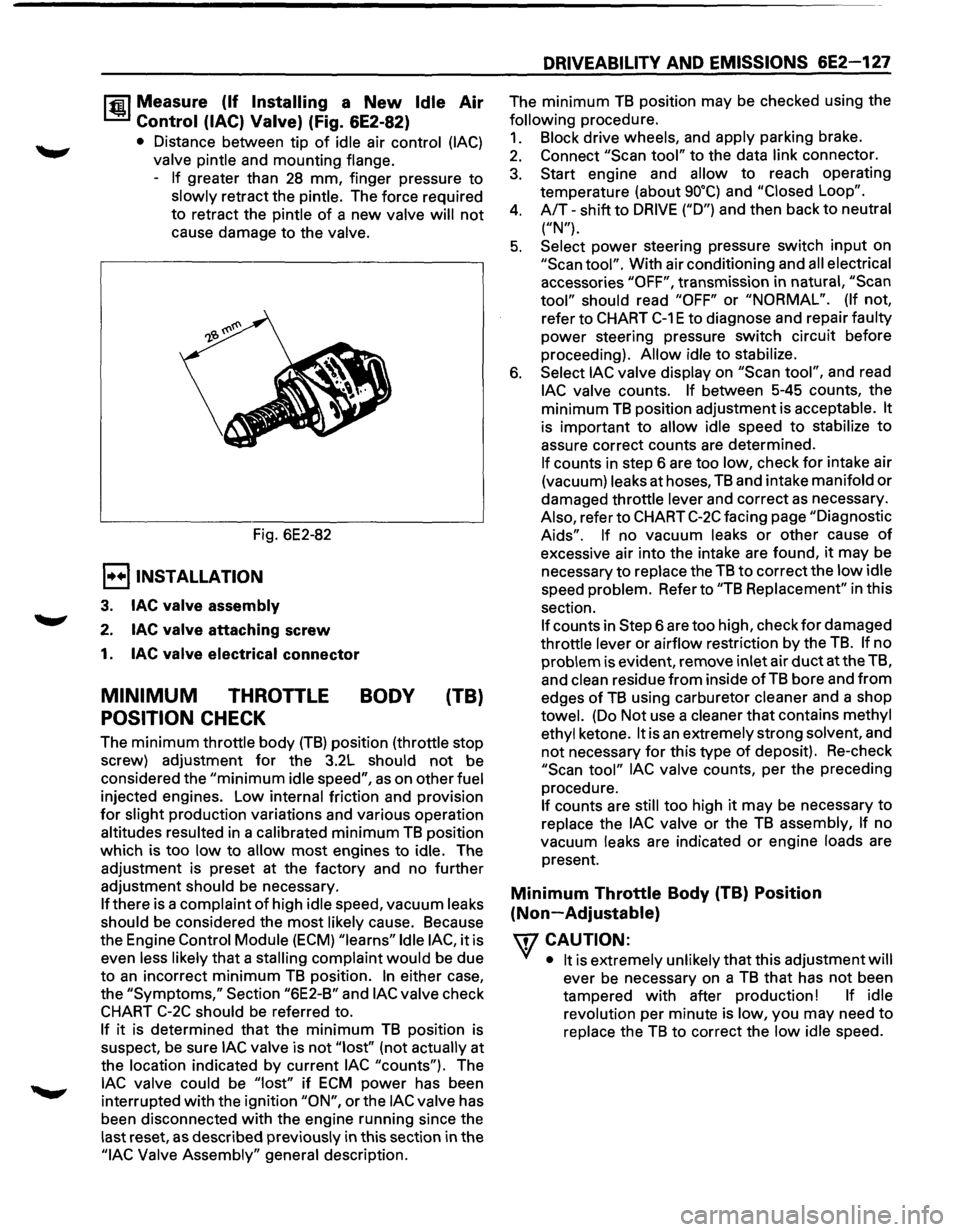
Control (lAC) Valve) (Fig. 6E2-82)
• Distance between tip of idle air control (lAC)
valve pintle and mounting flange.
-
If greater than 28 mm, finger pressure to
slowly retract the pintle. The force required
to retract the pintle
of a new valve will not
cause damage to the valve.
Fig. 6E2-82
E) INSTALLATION
3. lAC valve assembly
2. lAC valve attaching screw
1. lAC valve electrical connector
MINIMUM THROTTLE BODY (TB)
POSITION CHECK
The minimum throttle body (TB) position (throttle stop
screw) adjustment
for the 3.2L should not be
considered the
"minimum idle speed", as on other fuel
injected engines. Low internal friction and provision
for slight production variations and various operation
altitudes resulted in a calibrated
minimum TB position
which is too
low to allow most engines to idle. The
adjustment is preset at the factory and no further
adjustment should be necessary.
If there is a complaint of high idle speed, vacuum leaks
should be considered the
most likely cause. Because
the Engine
Control Module (ECM) "learns" Idle lAC, it is
even less likely
that a stalling complaint would be due
to
an incorrect minimum TB position. In either case,
the
"Symptoms," Section "6E2-B" and lAC valve check
CHART C-2C should be referred to.
If it is determined that the minimum TB position is
suspect,
be sure lAC valve is not "lost'' (not actually at
the location indicated by current
lAC "counts"). The
lAC valve could be "lost" if ECM power has been
interrupted
with the ignition "ON", or the lAC valve has
been disconnected
with the engine running since the
last reset,
as described previously in this section in the
"lAC Valve Assembly" general description.
DRIVEABILITY AND EMISSIONS 6E2-127
The minimum TB position may be checked using the
following procedure.
1. Block drive wheels, and apply parking brake.
2. Connect "Scan tool" to the data link connector.
3. Start engine and allow to reach operating
temperature (about
go•q and "Closed Loop".
4. A/T-shift to DRIVE ("D") and then back to neutral
("N").
5. Select power steering pressure switch input on
"Scan tool". With air conditioning and all electrical
accessories
"OFF", transmission in natural, "Scan
tool" should read "OFF" or "NORMAL". (If not,
refer to
CHART C-1 E to diagnose and repair faulty
power steering pressure switch circuit before
proceeding).
Allow idle to stabilize.
6. Select lAC valve display on "Scan tool", and read
lAC valve counts. If between 5-45 counts, the
minimum
TB position adjustment is acceptable. It
is important to allow idle speed to stabilize to
assure correct counts are determined.
If counts in step 6 are too low, check for intake air
(vacuum) leaks at hoses,
TB and intake manifold or
damaged throttle lever and correct as necessary.
Also, refer to
CHART C-2C facing page "Diagnostic
Aids". If no vacuum leaks or other cause of
excessive air into the intake are found, it may be
necessary
to replace the TB to correct the low idle
speed problem. Refer to
"TB Replacement" in this
section.
If counts in Step 6 are too high, check for damaged
throttle lever or airflow restriction by the
TB. If no
problem is evident, remove inlet air
duct at the TB,
and
clean residue from inside of TB bore and from
edges of TB using carburetor cleaner and a shop
towel. (Do Not use a cleaner that contains methyl
ethyl ketone.
It is an extremely strong solvent, and
not necessary for this type of deposit). Re-check
"Scan tool" lAC valve counts, per the preceding
procedure.
If counts are still too high it may be necessary to
replace the
lAC valve or the TB assembly, If no
vacuum leaks are indicated
or engine loads are
present.
Minimum Throttle Body (TB) Position
(Non-Adjustable)
\fl CAUTION:
VI • It is extremely unlikely that this adjustment will
ever be necessary on a TB that has not been
tampered
with after production! If idle
revolution per minute is low, you may need
to
replace the TB to correct the low idle speed.
Page 827 of 1928
DRIVEABILITY AND EMISSIONS 6E2-131
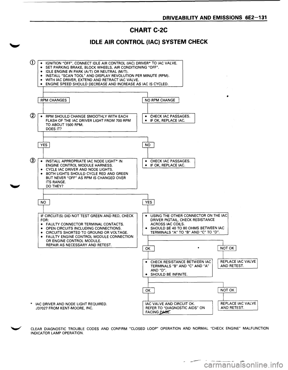
CHART C-2C
IDLE AIR CONTROL (lAC) SYSTEM CHECK
CD • IGNITION "OFF", CONNECT IDLE AIR CONTROL (lAC) DRIVER* TO lAC VALVE. • SET PARKING BRAKE, BLOCK WHEELS, AIR CONDITIONING "OFF".
• IDLE ENGINE IN PARK (A/T) OR NEUTRAL (MIT). • INSTALL "SCAN TOOL" AND DISPLAY REVOLUTION PER MINUTE (RPM). • WITH lAC DRIVER, EXTEND AND RETRACT lAC VALVE. • ENGINE SPEED SHOULD DECREASE AND INCREASE AS lAC IS CYCLED.
I
1 I • RPM CHANGES I NO RPM CHANGE I
I I • RPM SHOULD CHANGE SMOOTHLY
WITH EACH • CHECK lAC PASSAGES.
I FLASH OF THE lAC DRIVER LIGHT FROM 700 RPM • IF OK, REPLACE lAC.
TO ABOUT 1500 RPM. DOES IT?
I
~ cf
• INSTALL APPROPRIATE lAC NODE LIGHT* IN • CHECK lAC PASSAGES.
l ENGINE CONTROL MODULE HARNESS. • IF OK, REPLACE lAC. ®
• CYCLE lAC
DRIVER AND NODE LIGHTS.
• BOTH LIGHTS SHOULD CYCLE RED AND GREEN BUT NEVER "OFF" AS RPM IS CHANGED OVER
ITS RANGE. DO THEY?
I
cf ~ IF CIRCUIT(S) DID NOT TEST GREEN AND RED, CHECK •
USING THE OTHER CONNECTOR ON THE lAC
FOR: DRIVER
PIGTAIL, CHECK RESISTANCE
•
FAULTY CONNECTOR TERMINAL CONTACTS. ACROSS
lAC COILS.
• OPEN CIRCUITS INCLUDING CONNECTIONS. •
SHOULD BE 40 TO 80 OHMS BETWEEN lAC
• CIRCUITS SHORTED TO GROUND OR VOLTAGE. TERMINALS "A" TO "B" AND "C" TO "D".
• FAULTY ENGINE CONTROL MODULE CONNECTION I OR ENGINE CONTROL MODULE.
~
l REPAIR AS NECESSARY AND RETEST. l NOT OK I .
_l
• CHECK RESISTANCE BETWEEN lAC I REPLACE lAC VALVE I TERMINALS "B" AND "C" AND "A" AND RETEST. AND "D". • SHOULD BE INFINITE.
I
~
l
I NOT OK I
]
AC DRIVER AND NODE LIGHT REQUIRED. * I J lAC VALVE AND CIRCUIT OK. I REPLACE lAC VALVE J 37027 FROM KENT-MOORE, INC. REFER TO "DIAGNOSTIC AIDS" ON AND RETEST. FACING~
~ CLEAR DIAGNOSTIC TROUBLE CODES AND CONFIRM "CLOSED LOOP" OPERATION AND NORMAL "CHECK ENGINE" MALFUNCTION
INDICATOR LAMP OPERATION.
------
Page 830 of 1928
6E2-134 DRIVEABILITV AND EMISSIONS
SECTION C-3
EVAPORATIVE EMISSION (EVAP) CONTROL SYSTEM
(ELECTRONICALL V CONTROLLED)
CONTENTS
General Description ...................... 6E2-134
Purpose ............................ 6E2-134
Vapor Canister ........................ 6E2-134
Evaporative Emission (EVAP) Control System .. 6E2-134 Results of Incorrect Operation ............. 6E2-135
Diagnosis ............................. 6E2-135
Visual Check of Canister ................. 6E2-135
On-Vehicle service . . . . . . . . . . . . . . . . . . . . . . 6E2-135
Fuel Vapor Canister . . . . . . . . . . . . . . . . . . . . 6E2-135
Canister Hoses . . . . . . . . . . . . . . . . . . . . . . . 6E2-135
Chart C-3 Evaporate Emission Canister
Purge Valve . . . . . . . . . . . . . . . . . . . . . . . . . 6E2-136
GENERAL DESCRIPTION
PURPOSE
The basic Evaporative Emission (EVAP) Control
System used on
all vehicles is the charcoal canister
storage method. This method transfers fuel
vapor
from the fuel tank to an activated carbon (charcoal)
storage device (canister)
to hold the vapors when the
vehicle
is not operating. When the engine is running,
the fuel
vapor is purged from the carbon element by
intake air flow and consumed in the normal
combustion process.
VAPOR CANISTER
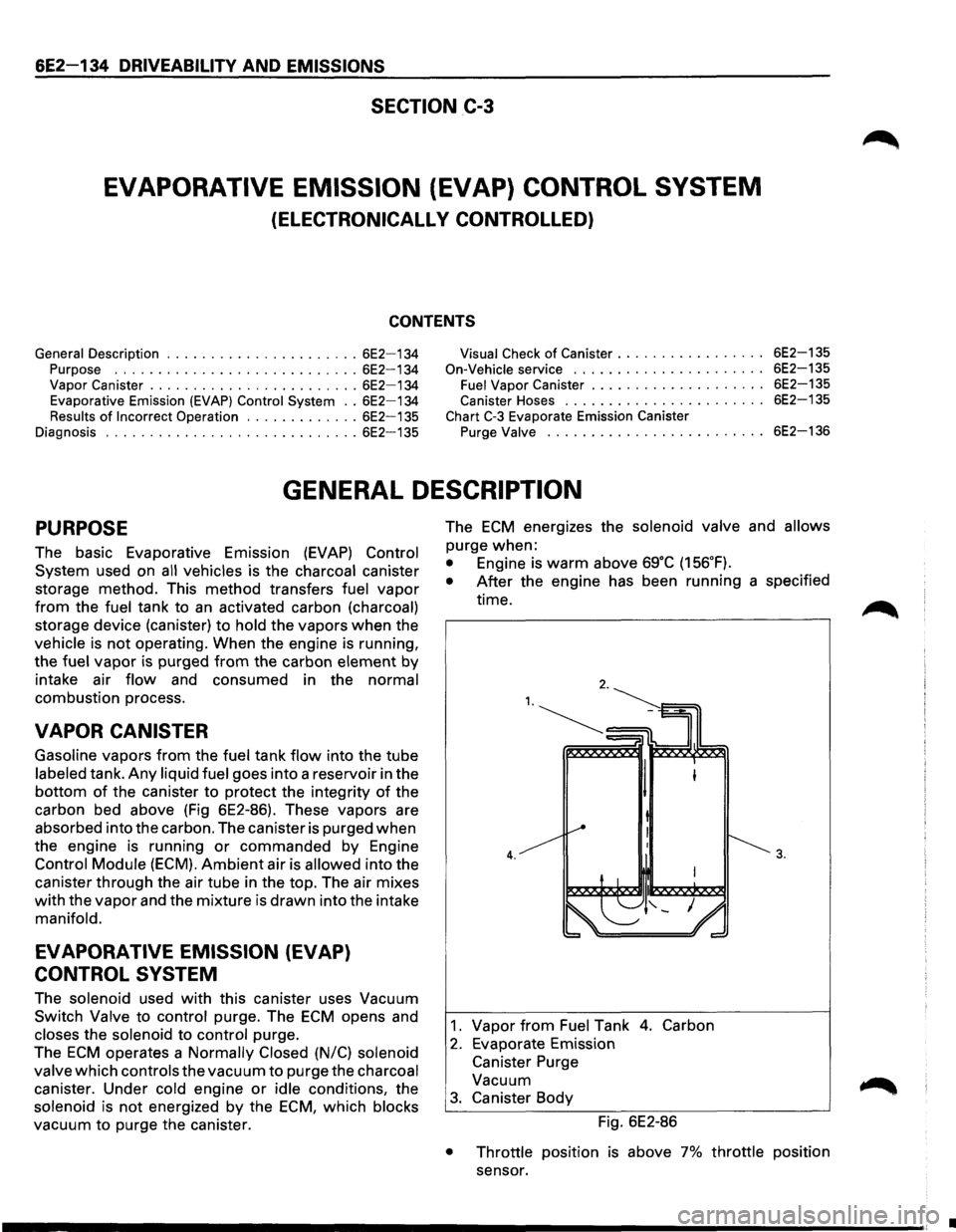
Gasoline vapors from the fuel tank flow into the tube
labeled tank.
Any liquid fuel goes into a reservoir in the
bottom of the canister to protect the integrity of the
carbon bed above (Fig 6E2-86). These vapors are
absorbed into the carbon. The canister is purged
when
the engine is running or commanded by Engine
Control Module (ECM).
Ambient air is allowed into the
canister through the air tube in the top. The air mixes
with the vapor and the mixture is drawn into the intake
manifold.
EVAPORATIVE EMISSION (EVAP)
CONTROL SYSTEM
The solenoid used with this canister uses Vacuum
Switch Valve to control purge. The ECM opens and
closes the solenoid to control purge.
The
ECM operates a Normally Closed (N/C) solenoid
valve
which controls the vacuum to purge the charcoal
canister. Under cold engine
or idle conditions, the
solenoid is
not energized by the ECM, which blocks
vacuum
to purge the canister. The
ECM energizes
the solenoid valve and allows
purge when:
• Engine is warm above sg·c (156.F).
• After the engine has been running a specified
time.
4.
1. Vapor from Fuel Tank 4. Carbon
2. Evaporate Emission
Canister Purge
Vacuum
3. Canister Body
Fig. 6E2-86
3.
• Throttle position is above 7% throttle position
sensor.
•
Page 832 of 1928
6E2-136 DRIVEABILITY AND EMISSIONS
CHART C-3
EVAPORATIVE EMISSION CANISTER PURGE VALVE CHECK
Circuit Description:
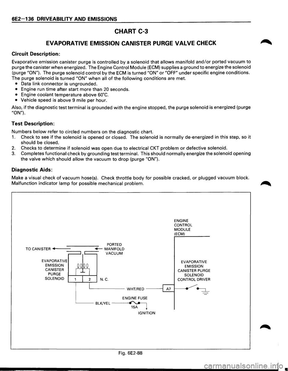
Evaporative emission canister purge is controlled by a solenoid that allows manifold and/or ported vacuum to
purge the canister when energized. The Engine Control Module (ECM) supplies a ground to energize the solenoid
(purge "ON"). The purge solenoid control by the ECM is turned "ON" or "OFF" under specific engine conditions.
The purge
solenoid is turned "ON" when all of the following conditions are met.
• Data link connector is ungrounded.
• Engine run time after start more than 20 seconds.
• Engine coolant temperature above 60°C.
• Vehicle speed is above 9 mile per hour.
Also, if the diagnostic test terminal is grounded with the engine stopped, the purge solenoid is energized (purge
"ON").
Test Description:
Numbers below refer to circled numbers on the diagnostic chart.
1. Check to see if the solenoid is opened or closed. The solenoid is normally de-energized in this step, so it
should be closed.
2. Checks to determine if solenoid was open due to electrical CKT problem or defective solenoid.
3. Completes functional check by grounding test terminal. This should normally energize the solenoid opening
the
valve which should allow the vacuum to drop (purge "ON").
Diagnostic Aids:
Make a visual check of vacuum hose(s). Check throttle body for possible cracked, or plugged vacuum block.
Malfunction
indicator lamp for possible mechanical problem.
EVAPORATIVE
EMISSION CANISTER
PURGE SOLENOID N.C.
L__ _____ WHT/RED -----;
ENGINE FUSE
BLKJYEL~ 15A ~
IGNITION
Fig. 6E2-88
ENGINE
CONTROL
MODULE (ECM)
EVAPORATIVE EMISSION
CANISTER
PURGE SOLENOID
CONTROL DRIVER
•
Page 834 of 1928
6E2-138 DRIVEABILITY AND EMISSIONS
SECTION C4
ELECTRONIC IGNITION (EI) SYSTEM/IGNITION CONTROL (IC)
CONTENTS
General Description . . . . . . . . . . . . . . . . . . . . . 6E2-138
Purpose
............................ 6E2-138
Operation
........................... 6E2-138
Results of Incorrect Operation . . . . . . . . . . . 6E2-139
How diagnostic trouble code (DTC) 42 is
Determined ........................ 6E2-139
Diagnosis. . . . . . . . . . . . . . . ............. 6E2-139
Diagnostic
trouble code (DTC) 12 . . . . . . . . . 6E2-139
On-Vechicle Service . .
. . . . . . . . . . . . . . . . . . . 6E2-139
Electronic Ignition (EI) Assembly .......... 6E2-139
Crankshaft Position (CKP) Sensor ......... 6E2-140
Ignition Coil
.......................... 6E2-140
Ignition Control
Module (ICM) ............ 6E2-140
Ignition
Timing ....................... 6E2-140
Chart
C-4D-1 Electronic Ignition (EI) misfire
at
Idle .............................. 6E2-142
Chart C-4D-2 Electronic Ignition (EI) misfire
Under Load .......................... 6E2-144
GENERAL DESCRIPTION
PURPOSE
The Electronic Ignition (EI) system controls fuel
combustion by providing a spark to ignite the
compressed
air/fuel mixture at the correct time. To
provide improved engine performance,
fuel economy,
and
control of exhaust emissions, the Engine Control
Module
(ECM) controls spark advance timing with the
Ignition Control (IC) system.
OPERATION
The "EI" is a "waste spark" system in which 2 plugs are
fired
simultaneously from one coil. The spark plugs are
paired
to a coil, so that when both fire, one cylinder is
on the compression stroke and the other is on exhaust.
There is
Iitie resistance across the plug gap on the
exhaust stroke, so the
plug requires very little voltage
to fire, thereby providing the other plug (compression)
with maximum available voltage.
The system uses a magnetic Crankshaft Position (CKP)
sensor which protrudes into the block, within
approximately .050" of the crankshaft reluctor. The
reluctor is a special wheel cast on the crankshaft that
has seven machined
slots, six of which are equally
spaced 60° apart). The seventh slot is spaced 1 oo from
one
of the other slots. As the reluctor rotates with the
crankshaft, the
slots change the magnetic field of the
sensor, causing
an induced voltage pulse.
By counting the time between pulses, the Ignition
Control Module (ICM)
can recognize the pulse of the
seventh
slot (sync pulse). Based on this sync pulse, the
module sends the reference signal to the ECM to
calculate CKP (used to fire coils in correct sequence)
and engine speed.
To
properly control timing, the ECM relies on the
following information:
• Engine load (manifold absolute pressure or
vacuum).
• Atmospheric (barometric) pressure.
• Engine temperature.
• Intake air temperature.
• CKP
• Engine speed (revolution per minute).
The ignition
control system consisits of the "EI"
assembly (coils, module,
and CKP sensor), ECM and
connecting wires. These circuits
perform the following
functions:
• "EI" reference
The CKP sensor sends a signal to the ICM which
generates a reference
pulse which is sent to the
ECM. The ECM uses this signal to calculate CKP
and engine speed (also used to trigger the
injector).
• Reference ground (GND)
This wire is GNd through the module and makes
sure the GNd circuit has no
voltage drop between
the
ICM and the ECM, which if open, could affect
performance.
• Bypass
At about 400 revolution per minute, the ECM
applies 5 volts to this circuit to switch spark timing
control from the ICM to the ECM. An open or
grounded bypass circuit
will set a diagnostic
trouble code 42 and the engine will run at base
timing,
plus a small amount of advance built into
the
ICM.
• IGNITION CONTROL (IC)
The ECM uses this circuit (when bypass voltage is
applied) to trigger the "EI" module. The ECM uses
the
CKP to base its calculation of the amount of
spark advance needed under present engine
conditions.
•