wiring ISUZU TROOPER 1995 Manual PDF
[x] Cancel search | Manufacturer: ISUZU, Model Year: 1995, Model line: TROOPER, Model: ISUZU TROOPER 1995Pages: 1928
Page 905 of 1928
AUTOMATIC TRANSMISSION (4L30·E) 7 A-33
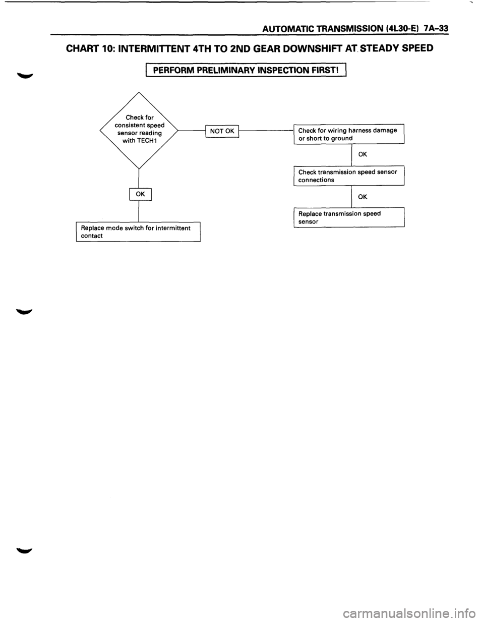
CHART 10: INTERMITTENT 4TH TO 2ND GEAR DOWNSHIFT AT. STEADY SPEED
PERFORM PRELIMINARY INSPECTION FIRST!
Check for consistent speed
sensor reading
with TECH1
Replace mode switch for intermittent
contact
1-------1 Check for wiring harness damage L...------1 or short to ground
OK
Check transmission speed sensor
connections
OK
Replace transmission speed
sensor
Page 917 of 1928
ELECTRONIC DIAGNOSIS
HOW TO DIAGNOSE THE PROBLEM
~ 1. To avoid incorrect diagnostics: this book needs
to be followed accurately. Unless stated: do
not jump
directly to a section that could
contain the solution: some important
information may be missed.
2. The sections in CAPITALS and bold are the
main sections that can be found in the
contents.
3. The GOTO "SECTION" means to continue to
check going to the "section".
4. The GOTHROUGH "SECTION" means to go
through the "section" and then to go back to
the place the GOTHROUGH was written.
5. BASIC ELECTRIC CIRCUITS:
You should understand the basic theory of
electricity. This will include the meaning of
voltage, amps, ohms, and what happens in a
circuit with an open or shorted wire. You
should also be able to read and understand
wiring diagrams.
6. IGNITION CYCLE:
When the car is driven a malfunction can occur
due to a car wiring harness problem, in this
case the driver can reset the system (as on a
personal computer). To reset the computer he
must: (
1) Stop the car and the engine.
(2) Turn the key ignition OFF.
(3) Turn the key ignition ON.
AUTOMATIC TRANSMISSION (4L30·E) 7 A-45
Page 920 of 1928
7 A-48 AUTOMATIC TRANSMISSION (4L30-E)
"CHECK TRANS" CHECK
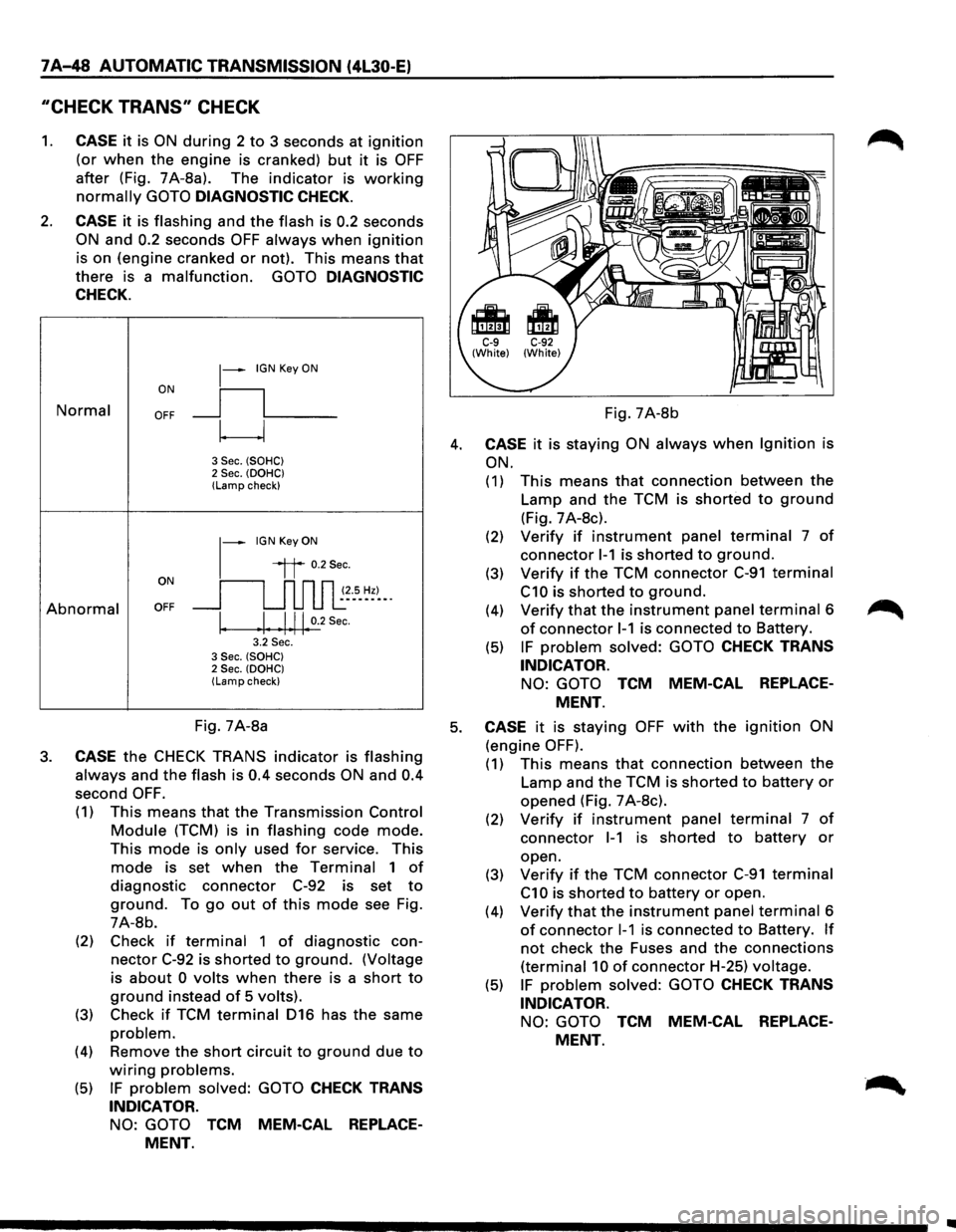
1. CASE it is ON during 2 to 3 seconds at ignition
(or when the engine is cranked) but it is OFF
after (Fig. 7A-8a). The indicator is working
normally GOTO DIAGNOSTIC CHECK.
2. CASE it is flashing and the flash is 0.2 seconds
ON and 0.2 seconds OFF always when ignition
is on (engine cranked or not). This means that
there is a malfunction. GOTO DIAGNOSTIC
CHECK.
Normal
Abnormal
~-IGN Key ON
ON
II
OFF __j l___
~
3 Sec. (SOHC) 2 Sec. (OOHC) (Lamp check)
1-
IGN Key ON
il 0.2Sec.
oN 11 n n n ~~--s_ ~~)-_. OFF __j u u u l:
I. .I. .1.11. 0.2
Sec.
3.2 Sec. 3 Sec. (SOHC) 2 Sec. (OOHC) (Lamp check)
Fig. 7A-8b
4. CASE it is staying ON always when Ignition is
ON.
(1) This means that connection between the
Lamp and the TCM is shorted to ground
(Fig. 7 A-8c).
(2) Verify if instrument panel terminal 7 of
connector 1-1 is shorted to ground.
(3) Verify if the TCM connector C-91 terminal
C10 is shorted to ground.
(4) Verify that the instrument panel terminal 6
of connector 1-1 is connected to Battery.
(5) IF problem solved: GOTO CHECK TRANS
INDICATOR.
NO: GOTO TCM MEM-CAL REPLACE
MENT.
Fig. 7A-8a 5. CASE it is staying OFF with the ignition ON
(engine OFF). 3. CASE the CHECK TRANS indicator is flashing
always and the flash is 0.4 seconds ON and 0.4
second OFF.
(1) This means that the Transmission Control
Module (TCM) is in flashing code mode.
This mode is only used for service. This
mode is set when the Terminal 1 of
diagnostic connector C-92 is set to
ground. To go out of this mode see Fig.
7A-8b.
(2) Check
if terminal 1 of diagnostic con
nector C-92 is shorted to ground. (Voltage
is
about 0 volts when there is a short to
ground instead of 5 volts).
(3) Check if TCM terminal 016 has the same
problem.
(4) Remove the short circuit to ground due to
wiring problems.
(5) IF problem solved: GOTO CHECK TRANS
INDICATOR.
NO: GOTO TCM MEM-CAL REPLACE
MENT.
(1) This means that connection between the
Lamp and the TCM is shorted to battery or
opened (Fig. 7 A-8c).
(2) Verify if instrument panel terminal 7 of
connector 1-1 is shorted to battery or
open.
(3)
Verify if the TCM connector C-91 terminal
C1 0 is shorted to battery or open.
(4)
Verify that the instrument panel terminal 6
of connector 1-1 is connected to Battery. If
not check the Fuses and the connections
(terminal 10 of connector H-25) voltage.
(5) IF problem solved: GOTO CHECK TRANS
INDICATOR.
NO: GOTO TCM MEM-CAL REPLACE
MENT.
Page 922 of 1928
7 A-50 AUTOMATIC TRANSMISSION (4L30-E)
FLASHING CODES
1. ON BOARD DIAGNOSIS (SELF-DIAGNOSIS)
(1) The Transmission Control Module (TCM)
conducts a
self-test of most of the wiring
and components in the system each time
the key is turned ON. If a fault is detected
the TCM
will store a Diagnostic Trouble
Code (DTC) in memory. It's a number that
corresponds to a specific problem.
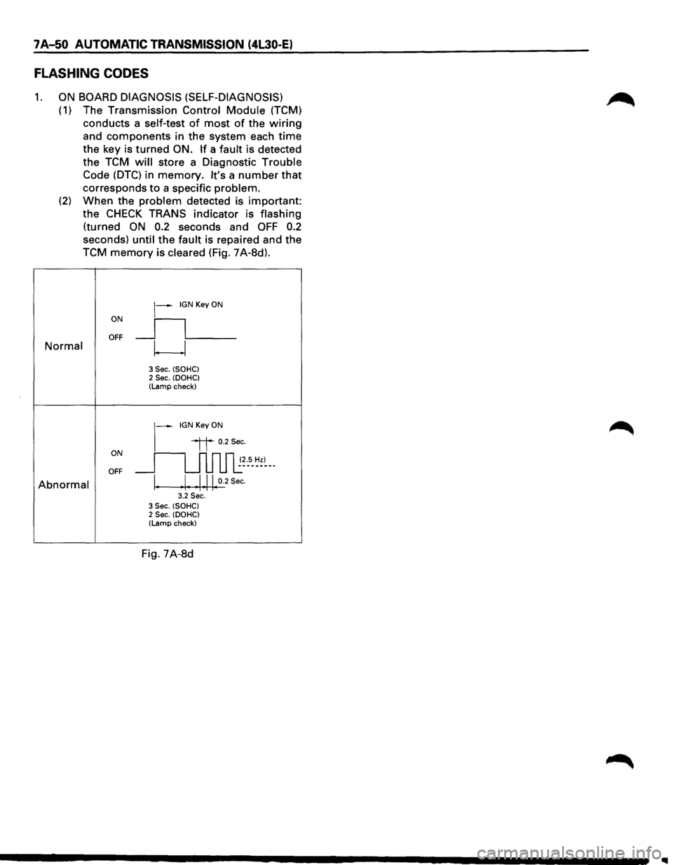
(2) When the problem detected is important:
the
CHECK TRANS indicator is flashing
(turned ON 0.2 seconds and OFF 0.2
seconds) until the fault is repaired and the
TCM
memory is cleared (Fig. 7A-8d).
ON
~--IGN Key ON
_ll___ OFF Normal w
3 Sec. (SOHC) 2 Sec. (DOHC) (Lamp check)
~-IGNKeyON
ON
"it 0.2Sec.
~~--5-~~)--· OFF
Abnormal \. Ill 0.2 Sec. • 1 ••.. 3.2 Sec. 3 Sec. (SOHC) 2 Sec. (DOHC) (Lamp check)
Fig. 7A-8d
Page 952 of 1928
1 A-80 AUTOMATIC TRANSMISSION (4L30-E)
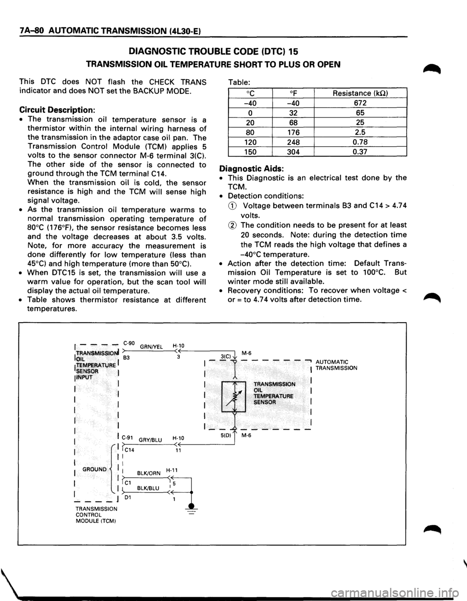
DIAGNOSTIC TROUBLE CODE (DTC) 15
TRANSMISSION OIL TEMPERATURE SHORT TO PLUS OR OPEN
This DTC does NOT flash the CHECK TRANS
indicator and does NOT set the BACKUP MODE.
Circuit Description:
• The transmission oil temperature sensor is a
thermistor within the internal wiring harness of
the transmission in the adaptor case oil pan. The
Transmission Control Module (TCM) applies 5
volts to the sensor connector M-6 terminal 3(C).
The
other side of the sensor is connected to
ground through the TCM terminal C14.
When the transmission oil is cold, the sensor
resistance is high and the TCM will sense high
signal voltage.
• As the transmission oil temperature warms to
normal transmission operating temperature of
80°C (176°F), the sensor resistance becomes less
and
the voltage decreases at about 3.5 volts.
Note,
for more accuracy the measurement is
done differently for low temperature (less than
45°C) and high temperature (more than 50°C).
•
When DTC15 is set, the transmission will use a
warm value for operation, but the scan tool will
display the actual oil temperature.
• Table shows thermistor resistance at different
temperatures.
Table:
oc OF Resistance (kQ)
-40 -40 672
0 32 65
20 68 25
80 176
2.5
120 248 0.78
150 304 0.37
Diagnostic Aids:
• This Diagnostic is an electrical test done by the
TCM.
• Detection conditions:
CD Voltage between terminals B3 and C14 > 4.74
volts.
@ The condition needs to be present for at least
20 seconds. Note: during the detection time
the TCM reads the high voltage that defines a
-40°C temperature.
• Action after the detection time: Default Trans
mission Oil Temperature is set to 100°C. But
winter mode still available.
• Recovery conditions: To recover when voltage <
or= to 4.74 volts after detection time.
f - ---C-90 GRN/YEL H-10 ITRANSMISSIONI >---'----<•((,--------3-(C--,) I M-6 to,,IL ~ 3 ~
ltEMf!EAATURE I I --1---- ---, AUTOMATIC
SENSOR I I I TRANSMISSION
llNPUT
I
I I
I TRANSMISSION L.... Oil I
I I I ~ TEMPERATURE
I I I / SENSOR I
I I I I
r I I __ _. _______ I
I I C-91 H-10 5(0) 1' M-6 GRY/BLU I ,. I >>---_:__--< < I IC14 11
I II
II I GROUND
I BLK/ORN H-11
1 1?c1 ~q I '-. I ~>--B_L__cKI_BL_U--<~ 5
----J 01
1
TRANSMISSION
CONTROL
MODULE ITCM)
Page 954 of 1928
7 A-82 AUTOMATIC TRANSMISSION (4L30-E)
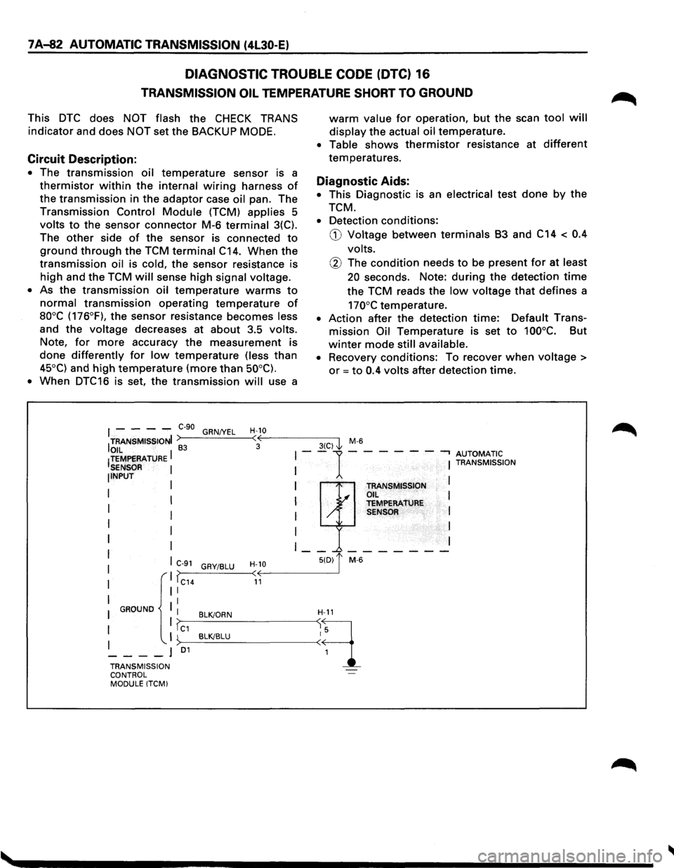
DIAGNOSTIC TROUBLE CODE (DTC) 16
TRANSMISSION OIL TEMPERATURE SHORT TO GROUND
This DTC does NOT flash the CHECK TRANS
indicator and does NOT set the BACKUP MODE.
Circuit Description:
• The transmission oil temperature sensor is a
thermistor within the internal wiring harness of
the transmission in the adaptor case oil pan. The
Transmission Control Module (TCM) applies 5
volts to the sensor connector M-6 terminal 3(C).
The
other side of the sensor is connected to
ground through the TCM terminal C14. When the
transmission oil is cold, the sensor resistance is
high and the TCM will sense high signal voltage.
•
As the transmission oil temperature warms to
normal transmission operating temperature of
aooc (176°F), the sensor resistance becomes less
and the voltage decreases at about 3.5 volts.
Note, for more accuracy the measurement is
done differently for low temperature (less than
45°C) and high temperature (more than 50°C).
•
When DTC16 is set, the transmission will use a
warm value for operation, but the scan tool will
display the actual oil temperature.
• Table shows thermistor resistance at different
temperatures.
Diagnostic Aids:
• This Diagnostic is an electrical test done by the
TCM.
• Detection conditions:
G) Voltage between terminals B3 and C14 < 0.4
volts.
@ The condition needs to be present for at least
20 seconds. Note: during the detection time
the TCM reads the low voltage that defines a
170°C temperature.
• Action after the detection time: Default Trans
mission Oil Temperature is set to 100°C. But
winter mode still available.
•
Recovery conditions: To recover when voltage >
or = to 0.4 volts after detection time.
I - - - -e-go GRN/YEL H-10
ITRANSMISSIONI >----'-----<:·oE---------3-(C-)-,'1 M-6
OIL I 83 I--1-- --- -.., AUTOMATIC !TEMPERATURE I I TRANSMISSION SENSOR NPUT I TRANSMISSION I .I OIL I I y TEMPERATURE I / SENSOR I
I
I I
I __ _.-------
C>--9_1_G_RY_I_BL_U_-
TRANSMISSION ~·· ... -l
CONTROL MODULE !TCM)
Page 967 of 1928
AUTOMATIC TRANSMISSION (4L30-E) 7 A-95
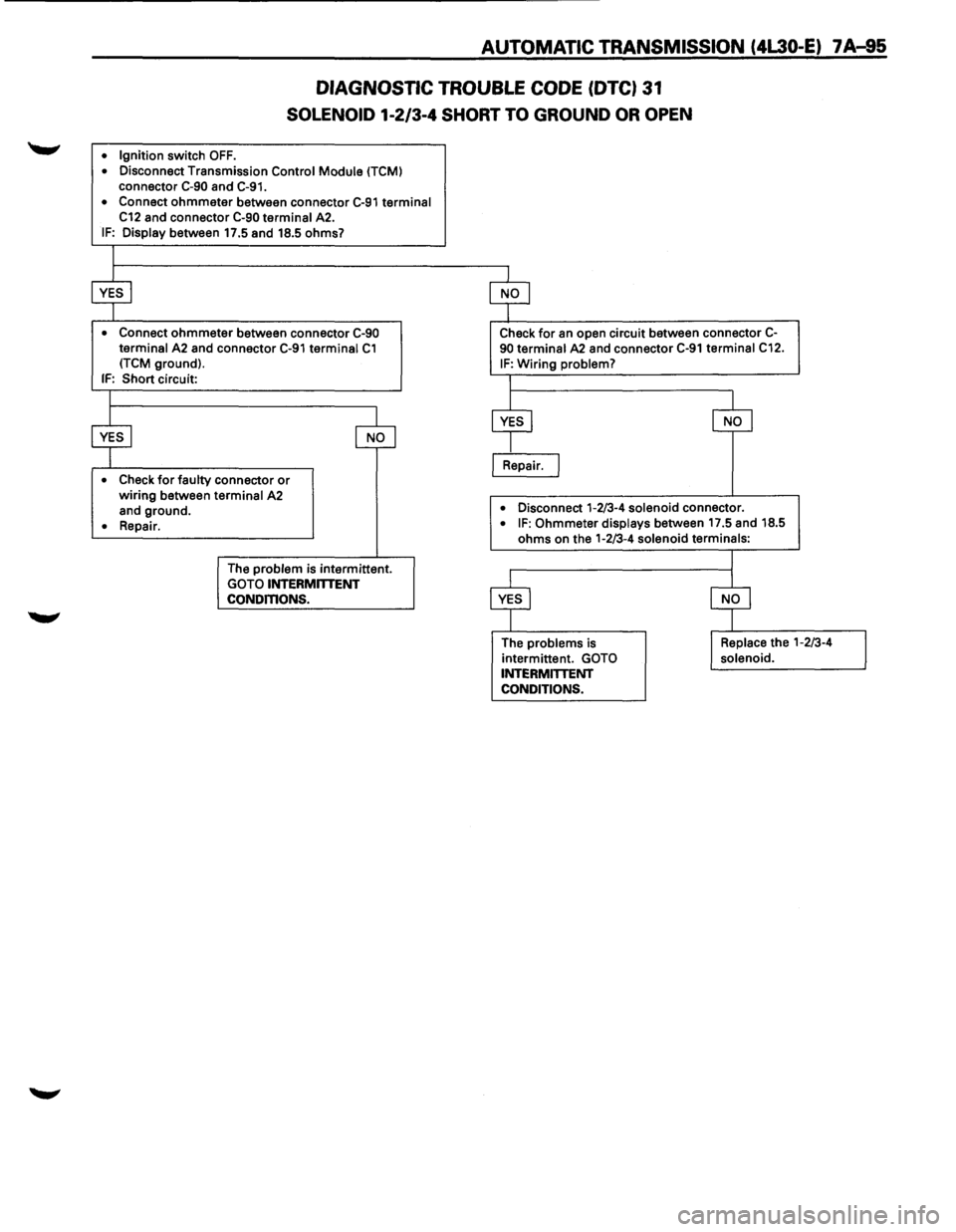
DIAGNOSTIC TROUBLE CODE (DTC) 31
SOLENOID 1-2/3-4 SHORT TO GROUND OR OPEN
• Ignition switch OFF. • Disconnect Transmission Control Module (TCM) connector C-90 and C-91.
•
Connect ohmmeter between connector C-91 terminal C12 and connector C-90 terminal A2. IF: Display between 17.5 and 18.5 ohms?
• Connect ohmmeter between connector C-90 terminal A2 and connector C-91 terminal C1 (TCM ground).
IF: Short circuit:
• Check for faulty connector or wiring between terminal A2
and ground.
• Repair.
The
problem is intermittent. GOTO INTERMITTENT CONDmONS.
Check for an open circuit between connector C-90 terminal A2 and connector C-91 terminal C12.
IF: Wiring problem?
I Repair.
• Disconnect 1-2/3-4 solenoid connector. • IF: Ohmmeter displays between 17.5 and 18.5
ohms on the 1-2/3-4
solenoid terminals:
The problems is
intermittent. GOTO INTERMITTENT
CONDITIONS.
Page 969 of 1928
AUTOMATIC TRANSMISSION (4L30-E) 7 A-97
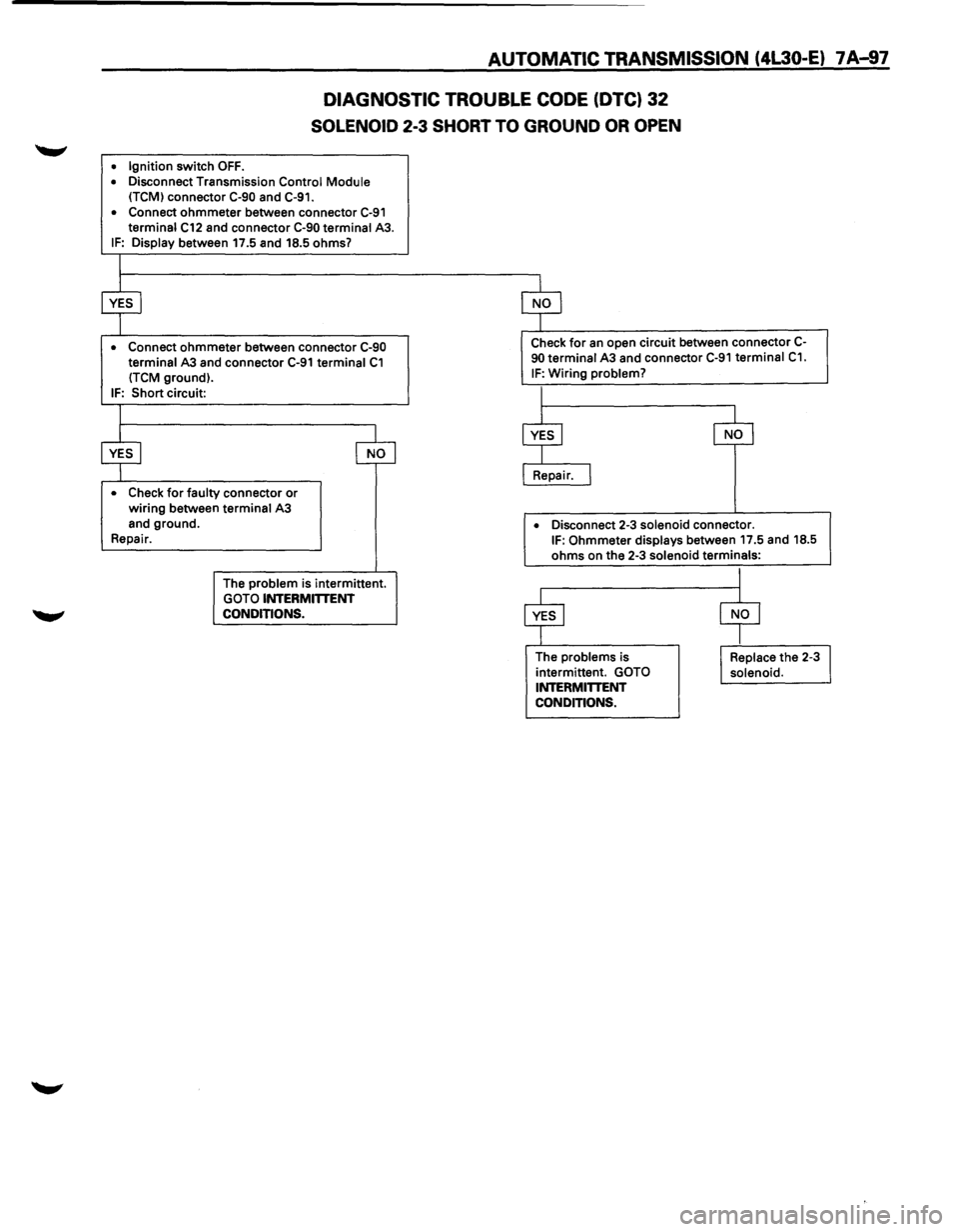
DIAGNOSTIC TROUBLE CODE (DTC) 32
SOLENOID 2-3 SHORT TO GROUND OR OPEN
• Ignition switch OFF. • Disconnect Transmission Control Module
(TCM) connector C-90 and C-91.
• Connect
ohmmeter between connector C-91 terminal C12 and connector C-90 terminal A3. IF: Display between 17.5 and 18.5 ohms?
• Connect ohmmeter between connector C-90 terminal A3 and connector C-91 terminal C1 (TCM ground).
IF: Short circuit:
• Check for faulty connector or wiring between terminal A3
and ground.
Repair.
The
problem is intermittent. GOTO INTERMITTENT
CONDITIONS.
Check for an open circuit between connector C-90 terminal A3 and connector C-91 terminal C1.
IF: Wiring problem?
•
Disconnect 2-3 solenoid connector. IF: Ohmmeter displays between 17.5 and 18.5 ohms on the 2-3 solenoid terminals:
The problems is
intermittent. GOTO INTERMITTENT
CONDITIONS.
Page 975 of 1928
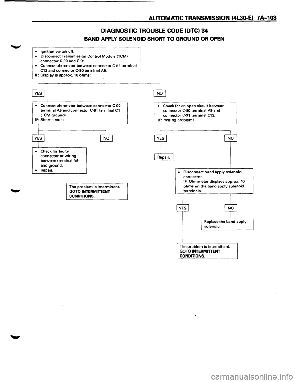
AUTOMATIC TRANSMISSION (4L30-E) 7 A-103
DIAGNOSTIC TROUBLE CODE (DTC) 34
BAND APPLY SOLENOID SHORT TO GROUND OR OPEN
• Ignition switch off. • Disconnect Transmission Control Module (TCM) connector C-90 and C-91
• Connect ohmmeter between connector C-91 terminal C12 and connector C-90 terminal A9. IF: Display is approx. 10 ohms:
• Connect ohmmeter between connector C-90 terminal A9 and connector C-91 terminal C1 (TCM ground)
IF: Short circuit:
• Check for faulty connector or wiring
between terminal A9
and ground.
• Repair.
The
problem is intermittent.
GOTO INTERMITTENT
CONDITIONS.
• Check for an open circuit between
connector C-90 terminal A9 and
connector
C-91 terminal C12. IF: Wiring problem?
•
Disconnect band apply solenoid connector. IF: Ohmmeter displays approx. 10
ohms on the band apply solenoid terminals:
The
problem is intermittent.
GOTO INTERMmENT CONDITIONS.
Page 979 of 1928
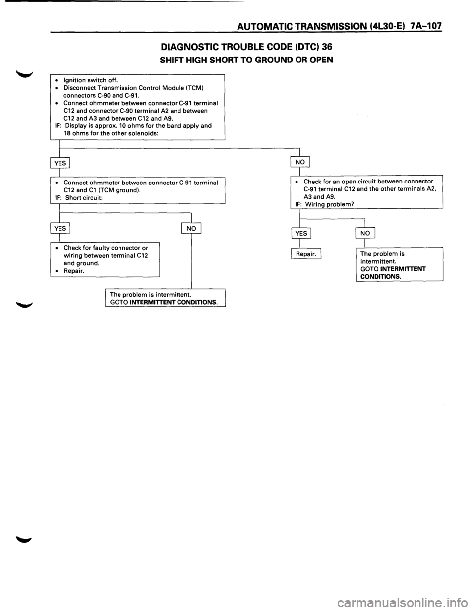
AUTOMATIC TRANSMISSION (4L30-E) 7A-107
DIAGNOSTIC TROUBLE CODE (DTC) 36
SHIFT HIGH SHORT TO GROUND OR OPEN
• Ignition switch off .
• Disconnect Transmission Control Module (TCM)
connectors C-90 and C-91.
• Connect ohmmeter between connector C-91 terminal C12 and connector C-90 terminal A2 and between
C12 and A3 and between C12 and A9. IF: Display is approx. 10 ohms for the band apply and 18 ohms for the other solenoids:
I
$ $
• Connect ohmmeter between connector C-91 terminal • Check for an open circuit between connector
C12 and C1 (TCM ground). C-91 terminal C12 and the other terminals A2,
IF: Short circuit: A3
and A9.
I IF: Wiring problem?
I
$ 8
$ $ • Check for faulty connector or wiring between terminal C12 I Repair. I The problem is
and ground. intermittent.
• Repair
. GOTO INTERMmENT
CONDITIONS.
I The problem is intermittent. GOTO INTERMITTENT CONDITIONS.