spare wheel Lancia Delta 2010 Owner handbook (in English)
[x] Cancel search | Manufacturer: LANCIA, Model Year: 2010, Model line: Delta, Model: Lancia Delta 2010Pages: 276, PDF Size: 5.31 MB
Page 19 of 276
18GETTING TO KNOW YOUR CAR
If the Ywarning light (or symbol in the display) is blinking,
this means that the vehicle is not protected by the engine in-
hibitor device (see “Lancia Code system” in chapter 1).
Contact a Lancia Dealership to have all the keys stored.
Alarm failure
(for versions/markets, where provided)
A fault with the alarm system is signalled by this warn-
ing light (or symbol in the display) coming on. Contact a
Lancia Dealership as soon as possible.
The display will show a dedicated message.
Break-in attempt
(for versions/markets, where provided)
This warning light (or symbol on the display) comes on
when a break-in attempt is detected. Contact a Lancia
Dealership as soon as possible.
The display will show a dedicated message.The warning light (amber), or symbol on the display (red),
lights up when the inflation pressure of one or more tyres
falls below a preset level. In this way the T.P.M.S. system warns
the driver that one or more tyres may be dangerously flat and
liable to puncture (see “ T.P.M.S. system” in this chapter).
IMPORTANT Do not continue driving with one or more
tyres flat as vehicle driveability may be compromised. Stop
the car, avoiding harsh braking or steering manoeuvres. Re-
place the wheel immediately with the small spare wheel (for
versions/markets, where provided) or carry out a repair us-
ing the dedicated kit (see the paragraph on “Replacing a
wheel” in chapter 4) and contact a Lancia Dealership as
soon as possible.
Check tyre pressure
This warning light (for versions/markets, where provid-
ed) comes on when the ignition key is turned to MAR, but
it should go off after a few seconds.
The warning light (or symbol in the display) lights up to
indicate that a tyre is flat (see “T.P.M.S. system ” in this
chapter).
Should two or more tyres be flat, the display will show the
indications corresponding to each tyre in sequence. Restore
the correct inflation pressure values as soon as possible (see
paragraph “Cold inflation pressures” in chapter “6”). Insufficient tyre inflation pressure
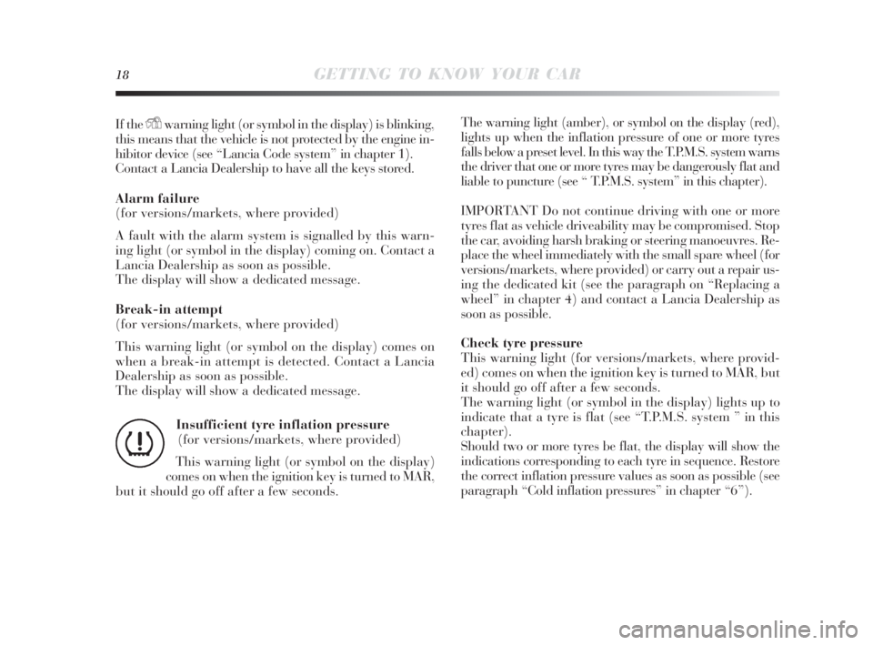
(for versions/markets, where provided)
This warning light (or symbol on the display)
comes on when the ignition key is turned to MAR,
but it should go off after a few seconds.
n
001-142 Delta 3ed gb 30-11-2009 11:21 Pagina 18
Page 95 of 276
94GETTING TO KNOW YOUR CAR
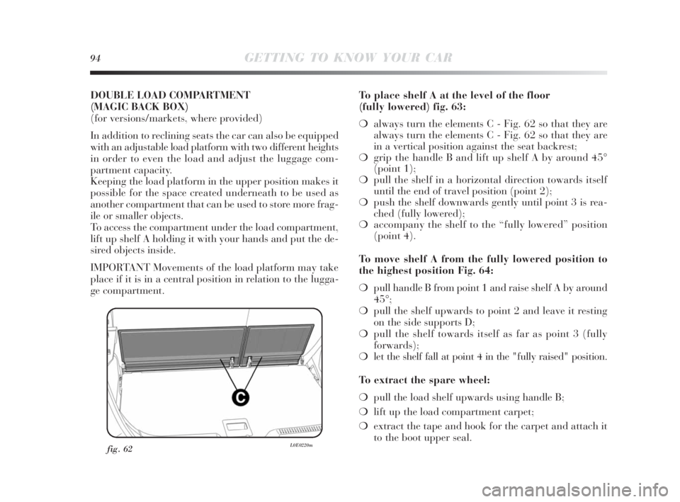
fig. 62L0E0220m
DOUBLE LOAD COMPARTMENT
(MAGIC BACK BOX)
(for versions/markets, where provided)
In addition to reclining seats the car can also be equipped
with an adjustable load platform with two different heights
in order to even the load and adjust the luggage com-
partment capacity.
Keeping the load platform in the upper position makes it
possible for the space created underneath to be used as
another compartment that can be used to store more frag-
ile or smaller objects.
To access the compartment under the load compartment,
lift up shelf A holding it with your hands and put the de-
sired objects inside.
IMPORTANT Movements of the load platform may take
place if it is in a central position in relation to the lugga-
ge compartment.To place shelf A at the level of the floor
(fully lowered) fig. 63:
❍always turn the elements C - Fig. 62 so that they are
always turn the elements C - Fig. 62 so that they are
in a vertical position against the seat backrest;
❍grip the handle B and lift up shelf A by around 45°
(point 1);
❍pull the shelf in a horizontal direction towards itself
until the end of travel position (point 2);
❍push the shelf downwards gently until point 3 is rea-
ched (fully lowered);
❍accompany the shelf to the “fully lowered” position
(point 4).
To move shelf A from the fully lowered position to
the highest position Fig. 64:
❍pull handle B from point 1 and raise shelf A by around
45°;
❍pull the shelf upwards to point 2 and leave it resting
on the side supports D;
❍pull the shelf towards itself as far as point 3 (fully
forwards);
❍let the shelf fall at point 4 in the "fully raised" position.
To extract the spare wheel:
❍pull the load shelf upwards using handle B;
❍lift up the load compartment carpet;
❍extract the tape and hook for the carpet and attach it
to the boot upper seal.
001-142 Delta 3ed gb 30-11-2009 11:22 Pagina 94
Page 112 of 276
GETTING TO KNOW YOUR CAR111
1
Failure indications
System failure is indicated by warning light
álighting up
on the instrument panel together with a dedicated mes-
sage appearing on the reconfigurable multifunctional dis-
play; see “Instrument panel warning lights”.
IMPORTANT The Hill Holder system is not a parking
brake; therefore, never leave the car without having en-
gaged the handbrake, turned the engine off and engaged
first gear.
If the small spare wheel is used, the Advanced
ESP system is still operational. Be aware,
however, that as the small spare wheel is
smaller than the original wheel, it provides less grip.
In order for the Advanced ESP and ASR systems to
operate correctly, the tyres must be of the same brand
and type on all wheels, in perfect condition and,
above all, be of the specified type, brand and size.
HILL HOLDER SYSTEM
This is an integral part of the ESP system and automati-
cally cuts in if one or both drive wheels slip, helping the
driver to control the car:
❍uphill: car at a standstill on a road with a gradient
higher than 5%, engine running, clutch and brake ped-
al pressed, gearbox to neutral or gear engaged other
than reverse;
❍downhill: car at a standstill on a road with a gradient
higher than 5%, engine running, clutch and brake ped-
al pressed and reverse gear engaged.
At take-off the Advanced ESP system control unit will
maintain a brake force on the wheels until the torque re-
quired for setting off is reached, or in any case for a max-
imum of 2 seconds so that the right foot can be moved eas-
ily from the brake pedal to the accelerator pedal.
After two seconds without setting off, the system will de-
activate automatically, gradually releasing the brake force.
During the release stage, the typical brake disengagement
noise may be heard, indicating that the car is going to
move.
001-142 Delta 3ed gb 30-11-2009 11:22 Pagina 111
Page 120 of 276

GETTING TO KNOW YOUR CAR119
1
Contact a
Lancia Dealership
Repairing a damaged
wheel
Contact a
Lancia Dealership
–
Contact a
Lancia Dealership.
––
NO
NO
YES
YES
YESYES
YES
YES
NO
NO
NO
(*) Given as an alternative in the Owner’s Handbook and available at Lineaccessori Lancia.
(**) Not swapped (tyres must stay on the same side).
In order to use the system properly, refer to the following table when you have to change wheels/tyres:
Operation Presence of sensor Indication Service Operation
fault Authorised Personnel
Lancia
–
Replacing a wheel with the
spare wheel
Replacing the wheels
with winter tyres
Replacing the wheels
with winter tyres
Replacing the wheels
with others of a different size (*)
Swapping the wheels
(front/rear) (**)
001-142 Delta 3ed gb 30-11-2009 11:22 Pagina 119
Page 175 of 276
174STARTING UP AND DRIVING
Keep your speed down when snow chains are
fitted. Do not exceed 50 km/h. Avoid potholes,
steps and pavements and avoid also driving
for long distances on roads not covered with snow
to avoid damaging the car and the roadbed.
SNOW CHAINS
The use of snow chains should be in compliance with lo-
cal regulations.
Snow chains may be applied only to the front wheel tyres
(drive wheels).
Check the tension of the chains after the first few metres
have been driven.
IMPORTANT The spare wheel cannot be fitted with snow
chains. If the front tyre has a puncture, replace a rear wheel
with the spare wheel and move the rear wheel to the front
axle. This way, having two standard size wheels on the
front axle, is it possible to fit the chains.
EXTENDED CAR INACTIVITY
If the car is to be left inactive for longer than a month, the
following precautions should be observed:
❍park the car in covered, dry and if possible well-ven-
tilated place;
❍engage a gear;
❍check that the handbrake is not engaged;
❍disconnect battery negative terminal and check the bat-
tery charge (see paragraph “Battery - Charge and elec-
trolyte level check” in chapter “5”);
❍clean and protect the painted parts of the vehicle with
protective wax;
❍clean and protect the shiny metal parts using special
compounds readily available;
❍sprinkle talcum powder on the rubber windscreen and
rear window wiper blades and lift them off the glass;
❍slightly open the windows;
❍cover the car with a fabric or perforated plastic sheet.
Do not use compact plastic sheets which do not allow
humidity to evaporate from the surface of the car;
❍inflate the tyres to a pressure of +0.5 bar above the
normal specified pressure and check the pressure at
regular intervals;
❍do not drain the engine cooling system.
165-174 Delta 3ed gb 11-11-2009 12:10 Pagina 174
Page 186 of 276
IN AN EMERGENCY185
4
REPLACING A WHEEL
GENERAL INSTRUCTIONS
The vehicle can be provided with (if requested, for ver-
sions/markets, where provided) a small spare wheel.
Wheel changing and correct use of the jack and of the
small spare wheel call for some precautions as listed
below.
The small spare wheel (for versions/markets,
where provided) is specific for your car. Do
not use it on different models of car. Do not
use spare wheels from different models on your car.
The small spare wheel must only be used in an
emergency. Never use it for more than strictly nec-
essary and never exceed 80 km/h. On the small
spare wheel there is an orange label, summarizing
the main warnings regarding small spare wheel us-
age restrictions.
Never remove or cover the label. Never apply
any hub cap on the small spare wheel. The
label contains the following indications in
four languages: Warning! For temporary use only!
80 km/h max! Replace as soon as possible with a
standard service wheel. Never cover this indication.
If you choose to install wheels of a different type
(with alloy rims instead of steel ones) you must al-
so change all the wheel retaining bolts with others
of a suitable size.
Indicate that the car is stationary according
to the laws in force: hazard warning lights,
refracting warning triangle, etc. Passengers
should leave the car, particularly if it is very loaded
and wait for the wheel to be changed away from on-
coming traffic. In the event of a wheel change on a
slope or on unsurfaced roads, chock the wheels.
175-214 Delta 4ed gb 24-02-2010 14:36 Pagina 185
Page 187 of 276
186IN AN EMERGENCY
Vehicle handling is modified with the small
spare wheel fitted. Avoid violent acceleration
and braking, sharp steering and fast bend-
ing. The overall duration of the small spare wheel
is of about 3000 km, after which the relevant tyre
must be replaced with another one of the same type.
Never install a traditional tyre on a rim designed to
be used as a small spare wheel. Repair and refit the
standard wheel as soon as possible. Using two or
more small spare wheels at the same time is for-
bidden. Do not apply grease to the bolt threads be-
fore assembly: they might come unscrewed.The jack may only be used to replace wheels
on the car which it equips or other cars of the
same model. Never use the jack for other pur-
poses, such as lifting other car models. Never use
the jack to carry out repairs under the car. Incor-
rect positioning of the jack may cause the car to fall.
Do not use the jack for loads higher than those
shown on the label. Never install snow chains on the
small spare wheel; if a front tyre (driving wheel)
is punctured and you need to use snow chains, use
a standard wheel from the rear axle and install the
small spare wheel on the rear axle. This way, with
two normal front driving wheels, you can install the
snow chains on them, thus resolving the emergency.
If the hub cap is not installed properly, it can
detach itself when the vehicle is running. Nev-
er tamper with the inflation valve. Never in-
troduce tools of any kind between rim and tyre.
Check tyre and small spare wheel pressure regu-
larly referring to the values shown in chapter “6”.
Tool box (versions with Bose Hi-Fi)
There is a tool box located in the luggage compartment
for versions with Bose Hi-Fi.
This box contains:
❍screwdriver;
❍tow hook;
❍wheel bolt spanner;
❍wheel bolt access spanner;
❍alloy wheel centering;
❍jack.
175-214 Delta 4ed gb 24-02-2010 14:36 Pagina 186
Page 188 of 276

IN AN EMERGENCY187
4
REMOVING THE SUBWOOFER
(versions with Bose HI-FI system)
(for versions/markets, where provided)
IMPORTANT The following procedure only applies to ve-
hicles equipped with Bose Hi-Fi systems with Subwoofer
(for versions/markets, where provided).
SUBWOOFER AND SMALL SPARE WHEEL
Proceed as follows to remove the Subwoofer:
❍open the luggage compartment, pull tab A-fig. 10 and
lift up the mat;
❍undo locking device A-fig. 8 and lift up the Subwoofer.
Then remove connection cable B from Velcro attach-
ment C;❍rest the Subwoofer to one side in the luggage com-
partment, remove the container and take out the small
spare wheel;
❍replace the wheel as described in this chapter.
After tyre replacement:
❍reposition the container and place the Subwoofer on
top of it, taking care to position it according to the in-
structions on the container (fig. 9) so that the arrow
on the spacer is pointing in the direction of travel;
❍rest cable B-fig. 8 into Velcro Attachment C to avoid
pinching it. Then tighten locking device A-fig. 8. Re-
place the luggage compartment mat.
fig. 8L0E0176mfig. 9L0E0177m
175-214 Delta 4ed gb 24-02-2010 14:36 Pagina 187
Page 189 of 276

188IN AN EMERGENCY
Taking out the small spare wheel
Important notes:
❍the jack weight is 1.76 kg;
❍the jack requires no adjustment;
❍the jack cannot be repaired; If it breaks it must be re-
placed with a new jack;
❍no tool other than the cranking device may be fitted
on the jack.
To replace a tyre proceed as follows:
❍stop the car in a position where it does not present a
danger for on-coming traffic and where you can re-
place the wheel safely. The ground must be flat and
compact;
❍turn the engine off and engage the handbrake;
❍engage first gear or reverse;
❍lift up the luggage compartment mat using handle A-
fig. 10 (in the presence of a double load platform, first
lift the upper cover and then the luggage compartment
mat);
❍loosen the fastener B-fig. 10;
❍take out the tool box C and place it next to the wheel
to be changed;
❍remove the small spare wheel D-fig. 10;
❍use the provided screwdriver to remove the hub cap,
levering the dedicated opening on the outer edge;
fig. 10L0E0081m
175-214 Delta 4ed gb 24-02-2010 14:36 Pagina 188
Page 191 of 276
190IN AN EMERGENCY
❍warn anybody nearby that the car is about to be lift-
ed. They must stay clear and not touch the car until
it is back on the ground;
❍fit the handle H-fig. 12 into device I of the jack and
lift the car until the wheel is several centimetres off the
ground. When turning the handle, make sure that it
rotates freely, without risking injury to your hand by
rubbing it against the ground. Even the moving com-
ponents of the jack (screws and joints) can cause in-
juries; do not touch them. If you come into contact with
lubricating grease, clean yourself thoroughly;
❍make sure the contact surfaces on the small spare wheel
are clean so that the retaining bolts will not come loose;
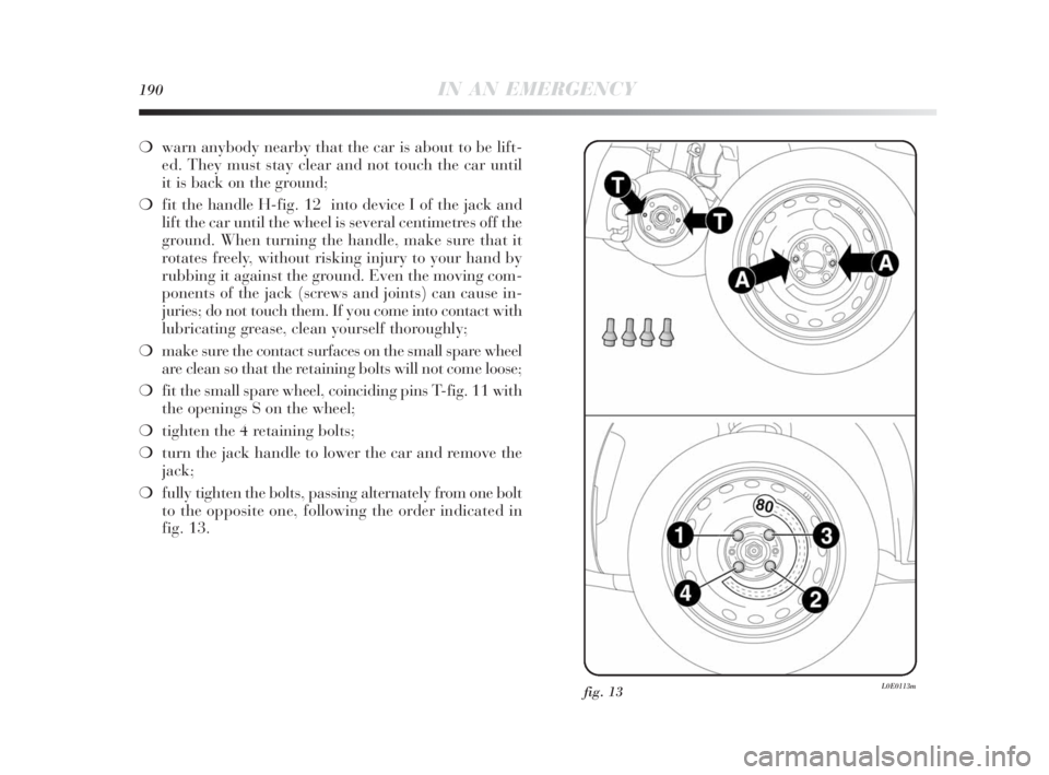
❍fit the small spare wheel, coinciding pins T-fig. 11 with
the openings S on the wheel;
❍tighten the 4 retaining bolts;
❍turn the jack handle to lower the car and remove the
jack;
❍fully tighten the bolts, passing alternately from one bolt
to the opposite one, following the order indicated in
fig. 13.
fig. 13L0E0113m
175-214 Delta 4ed gb 24-02-2010 14:36 Pagina 190