LAND ROVER FRELANDER 2 2006 Repair Manual
FRELANDER 2 2006
LAND ROVER
LAND ROVER
https://www.carmanualsonline.info/img/64/57251/w960_57251-0.png
LAND ROVER FRELANDER 2 2006 Repair Manual
Trending: child lock, USB, roof, oil filter, fuse diagram, ECU, oil dipstick
Page 811 of 3229
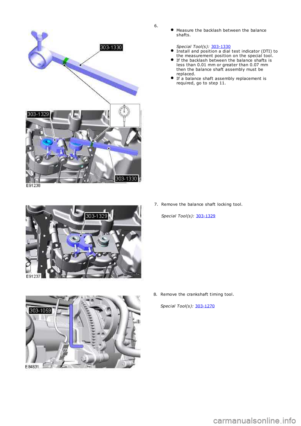
Meas ure t he backl as h bet ween the bal ance
s haft s.
Speci al Tool (s ): 303-1330 Inst all and posi ti on a di al t es t indicator (DTI) t o
t he meas urement pos i ti on on the special tool . If the backlas h between t he balance shafts i s
l es s t han 0.01 mm or great er than 0.07 mm
t hen the bal ance s haft as s embl y mus t be
repl aced. If a balance s haft ass embly replacement is
requi red, go to s tep 11. 6.
Remove t he bal ance shaft locki ng tool.
Speci al Tool (s ): 303-1329 7.
Remove the cranks haft t imi ng t ool .
Spec i al T ool(s ): 303-1270 8.
Page 812 of 3229
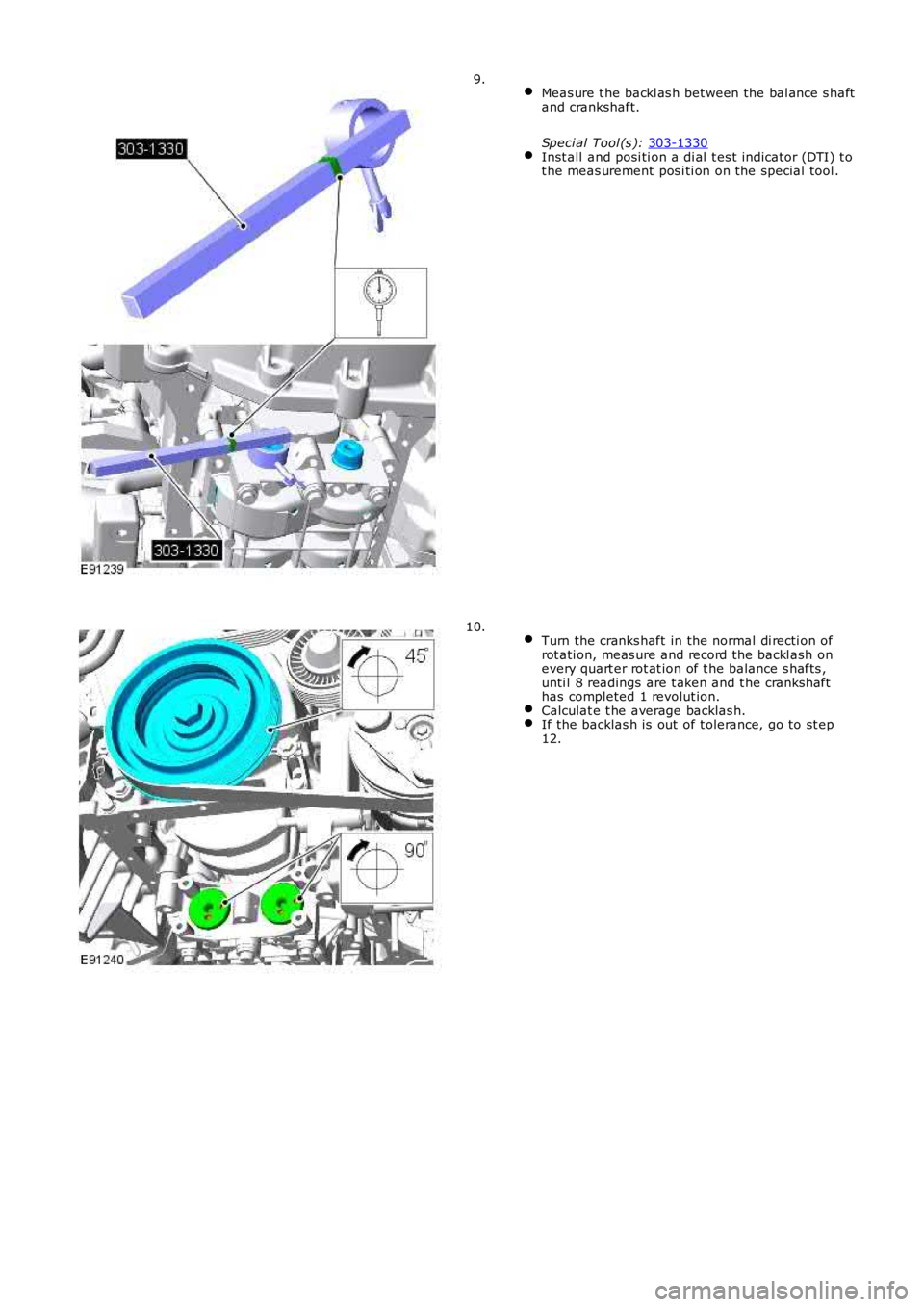
Meas ure t he backl as h bet ween the bal ance s haft
and crankshaft.
Speci al Tool (s ): 303-1330 Inst all and posi ti on a di al t es t indicator (DTI) t o
t he meas urement pos i ti on on the special tool . 9.
Turn the cranks haft in the normal di recti on of
rot ati on, meas ure and record the backl ash on
every quart er rot at ion of t he balance s hafts ,
unti l 8 readings are t aken and t he crankshaft
has completed 1 revolut ion. Calculat e t he average backlas h.
If the backlas h is out of t olerance, go to st ep
12. 10.
Page 813 of 3229
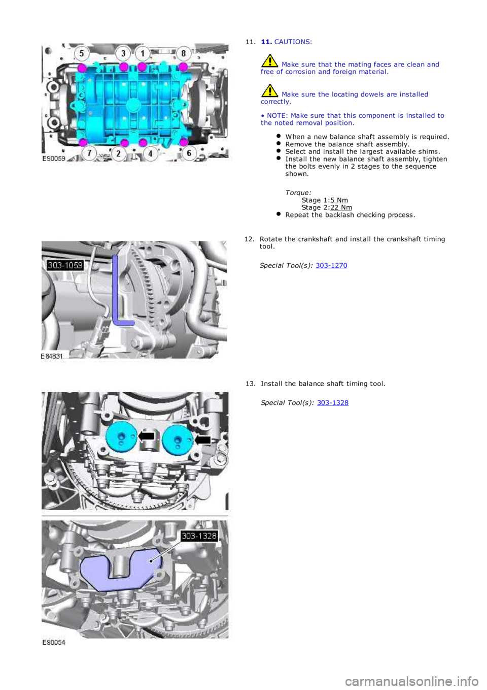
Stage 1:
Stage 2: 11.
CAUTIONS: Make s ure that t he mat ing faces are clean and
free of corros i on and forei gn mat erial . Make s ure the locat ing dowels are i nst all ed
correct ly.
• NOTE: Make s ure that t hi s component is ins tal led t o
t he noted removal pos it ion.
W hen a new balance s haft ass embl y is requi red. Remove t he bal ance shaft as s embly.
Select and ins tal l the l argest avail abl e s hims .
Inst all t he new balance s haft ass embly, t ighten
t he bolt s evenly in 2 s tages to the sequence
s hown.
T orque: 5 Nm 22 Nm
Repeat t he backl ash checki ng process .11.
Rotat e t he cranks haft and i nst all t he cranks haft t iming
tool .
Spec i al T ool(s ): 303-1270 12.
Inst all t he bal ance shaft ti ming t ool.
Speci al Tool (s ): 303-1328 13.
Page 814 of 3229
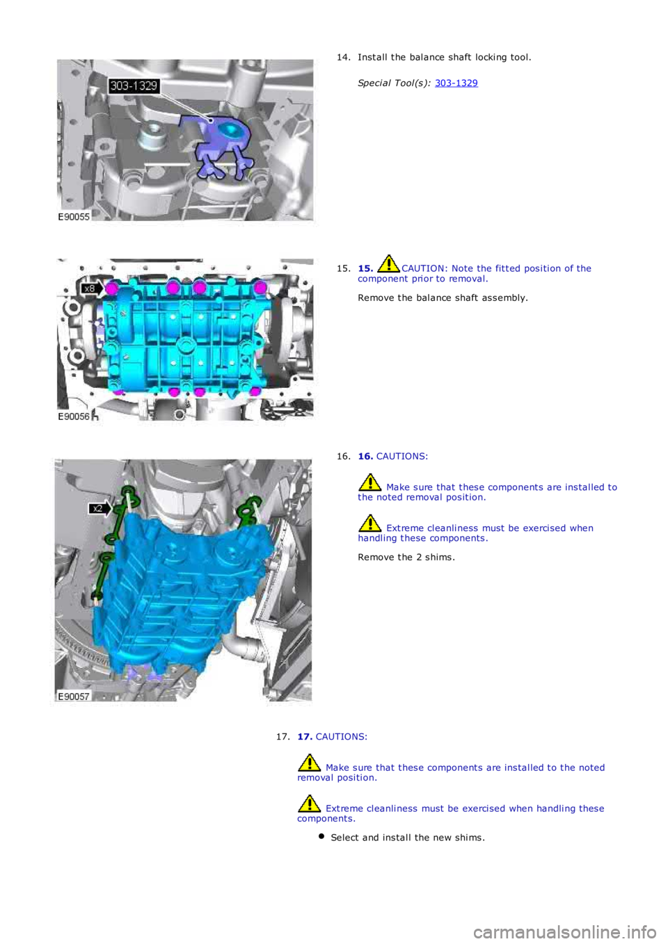
Inst all t he bal ance shaft locki ng tool.
Speci al Tool (s ): 303-1329 14.
15. CAUTION: Note the fit t ed pos i ti on of the
component pri or to removal.
Remove t he bal ance shaft as s embly.
15. 16.
CAUTIONS: Make s ure that t hes e component s are ins tal led t o
t he noted removal pos it ion. Ext reme cl eanli ness must be exerci sed when
handl ing t hese components .
Remove t he 2 s hims .
16.
17. CAUTIONS: Make s ure that t hes e component s are ins tal led t o t he noted
removal posi ti on. Ext reme cl eanli ness must be exerci sed when handli ng t hes e
component s.
Select and ins tal l the new shi ms . 17.
Page 815 of 3229
Stage 1:
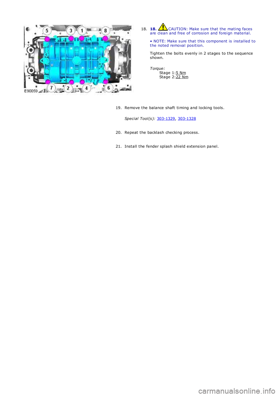
Stage 2: 18. CAUTION: Make s ure t hat the mati ng faces
are cl ean and free of corros ion and forei gn material.
• NOTE: Make s ure that t hi s component is ins tal led t o
t he noted removal pos it ion.
Tight en the bol ts evenly i n 2 s t ages to t he s equence
s hown.
T orque: 5 Nm 22 Nm18.
Remove t he bal ance shaft ti ming and l ocking tools .
Speci al Tool (s ): 303-1329 ,
303-1328 19.
Repeat t he backl ash checki ng process .
20.
Inst all t he fender spl as h shi el d extens ion panel.
21.
Page 816 of 3229
Publi s hed: 11-May-2011
Engine - TD4 2.2L Diesel - Intake Manifold
Removal and Inst all ati on
Removal
Di sconnect t he bat t ery ground cable.
Refer t o: Specificati ons (414-00 Bat tery and Charging Sys tem -General Informat ion, Specificati ons).
1.
2. W ARNING: Make sure t o s upport the vehicle wit h axles tands .
Rais e and s upport t he vehi cl e.
2.
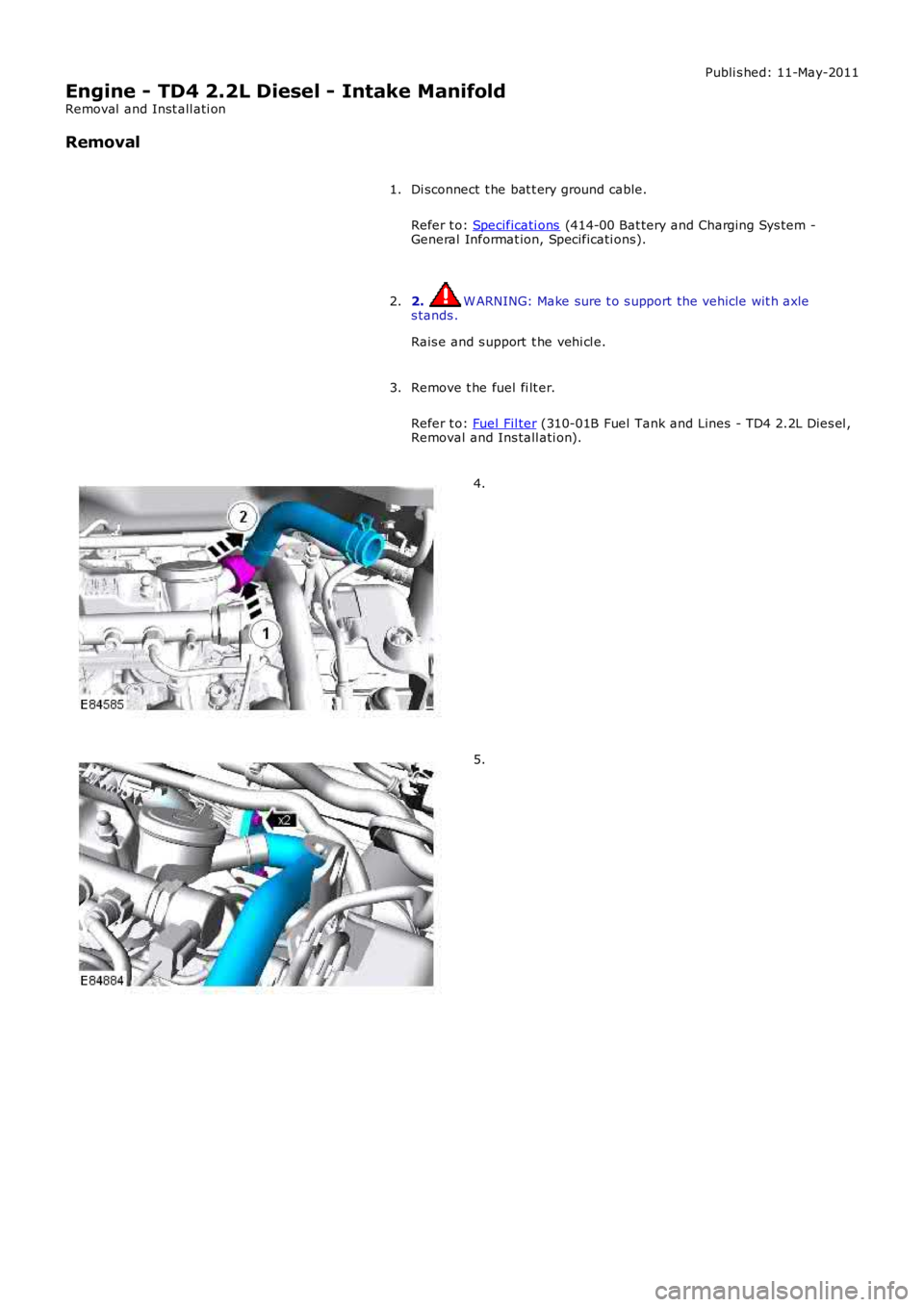
Remove t he fuel fi lt er.
Refer t o: Fuel Fil ter (310-01B Fuel Tank and Lines - TD4 2.2L Dies el ,Removal and Ins tall ati on).
3.
4.
5.
Page 817 of 3229
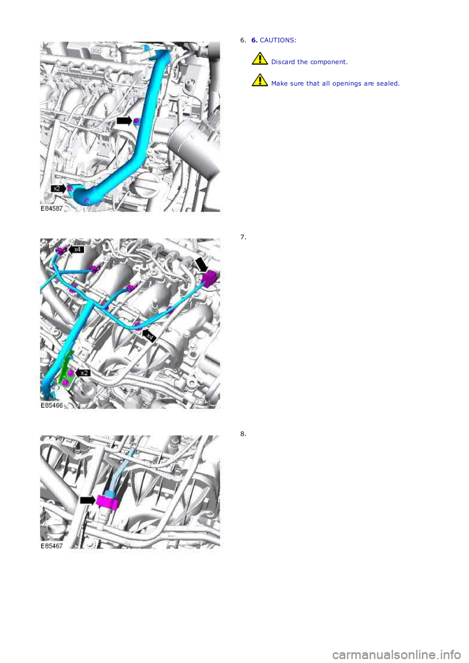
6. CAUTIONS:
Di s card the component.
Make s ure that all openings are sealed.
6.
7.
8.
Page 818 of 3229
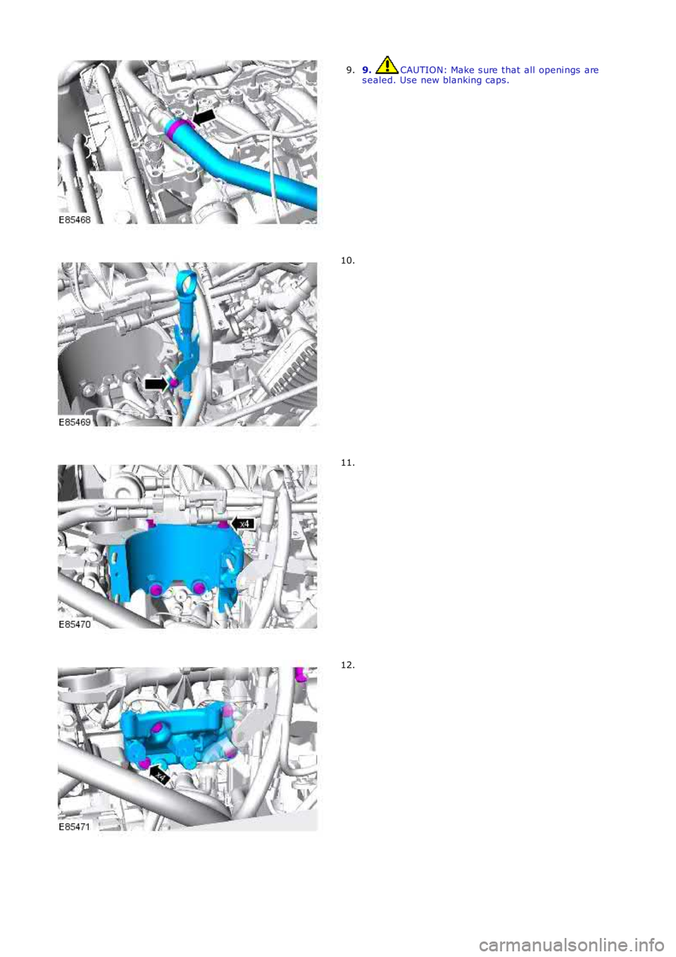
9. CAUTION: Make s ure that all openi ngs ares ealed. Use new blanking caps.9.
10.
11.
12.
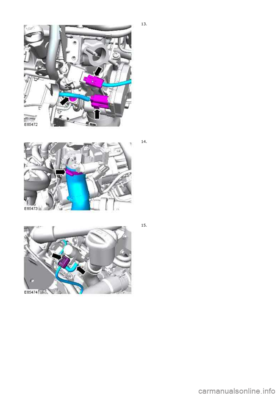
Page 819 of 3229
Page 820 of 3229
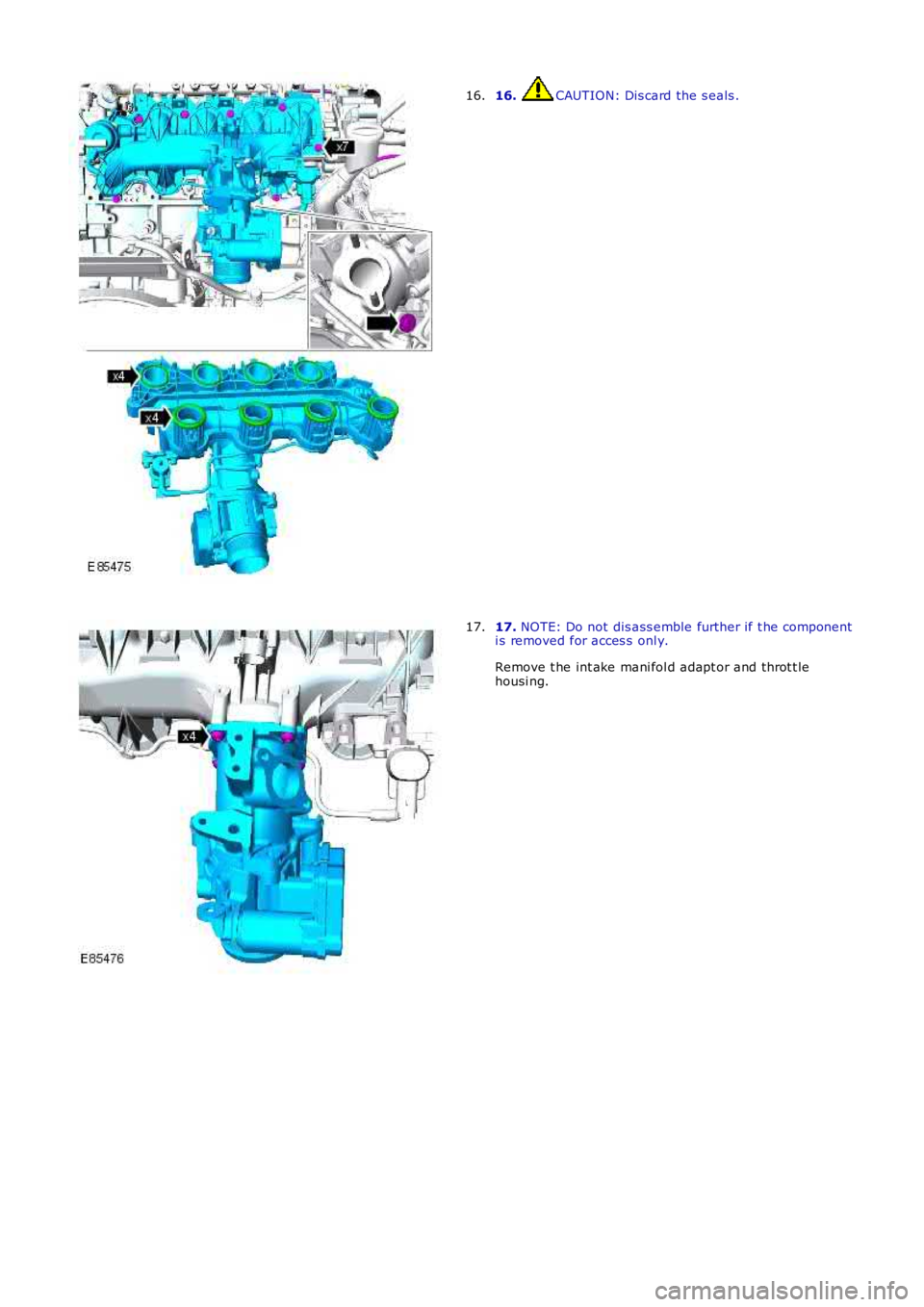
16. CAUTION: Dis card the s eals .16.
17. NOTE: Do not dis ass emble further if t he componenti s removed for acces s onl y.
Remove t he int ake mani fol d adapt or and throt t lehousi ng.
17.
Trending: ECO mode, service, wiper fluid, fuel cap release, dimensions, open bonnet, airbag
