engine MAZDA PROTEGE 1992 Workshop Manual
[x] Cancel search | Manufacturer: MAZDA, Model Year: 1992, Model line: PROTEGE, Model: MAZDA PROTEGE 1992Pages: 1164, PDF Size: 81.9 MB
Page 725 of 1164

FRONT SUSPENSION (STRUT) R
r
03UORX-03
STABILl2;ER BAR
I
Removal note
Stabilizer bar
1. Remove the nuts of the steering gear box mounting brack-
et, and move the gear box forward.
2. Support the engine with the
SST, and remove the cross-
member mounting bolts.
3. Lower the crossmember slowly, and remove the stabilizer
bar from the crossmember.
Installation note
Stabilizer bushing
Align the bushing with the installation position line painted on
the stabilizer bar.
Stabilizer nut
1. Tighten the stabilizer nut so that the specified thread is ex-
posed at the end of the bolt.
Specification: 17-l 9mm (0.67-0.75 in)
Stabilizer bar
1. Install the stabilizer bar to the crossmember.
2. Install the crossmember and tighten the mounting bolts to
the specified torque.
Tightening torque:
93-127 N#m (9.5-12.9 m-kg, 69-93 ft-lb)
3. Tighten the nuts of the steering gear box mounting bracket
to the specified torque.
Tightening torque:
37-52 N*m (3.6-5.3 m-kg, 27-36 ft-lb)
R-19
Page 869 of 1164
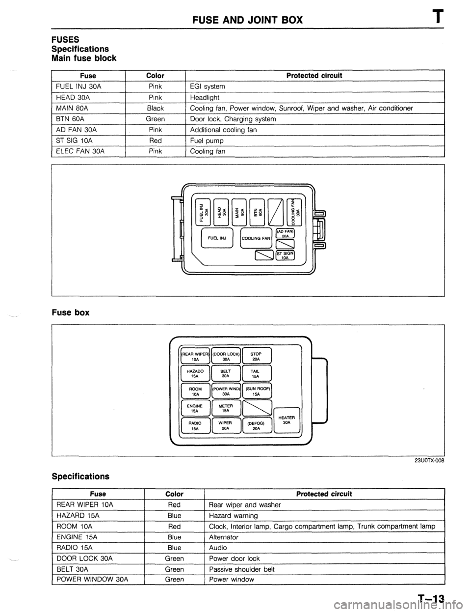
FUSE AND JOINT BOX
FUSES
Specifications
Main fuse block
Fuse Color
FUEL INJ 30A Pink
HEAD 30A Pink
MAIN 80A Black
BTN 60A Green
AD FAN 30A Pink
ST SIG 10A Red
ELEC FAN 30A Pink Protected circuit
EGI system
Headlight
Cooling fan, Power window, Sunroof, Wiper and washer, Air conditioner
Door lock, Charging system
Additional cooling fan
Fuel pump
Cooling fan
Fuse box
23UOTX-001
Specifications
Fuse
REAR WIPER 10A
HAZARD 15A
ROOM IOA
ENGINE 15A
RADIO 15A
DOOR LOCK 30A
BELT 30A
POWER WINDOW 30A Color
Red
Blue
Red
Blue
Blue
Green
Green
Green Protected circuit
Rear wiper and washer
Hazard warning
Clock, interior lamp, Cargo compartment lamp, Trunk compartment lamp
Alternator
Audio
Power door lock
Passive shoulder belt
Power window
1
T-13
Page 895 of 1164

EXTERIOR LIGHTING SYSTEM T
Stoplight
Circuit diaaram
GTOPLIGHTS F-2
SHIFT-LOCK
BLUB TRADE NUMBER
STOPLIGHT: 1157 (27W)
HIGH MOUNT
STOPLIGHT: 921 (18.4W) G (F) *ENGINE CONTROL UNIT
(SECTION B- lc;26)
G (F) *CRUISE CONTROL UNIT
(SECTION 01)
WITH REAR SPOILER
HIGH MOUNl-
STOPLIGHT
STOPLIGHT STOPLIGHT
-06 STOPLIGHT
SWITCH (F) F-07 HIGH MOUNT STOP-E-12 STOPLIGHT LH(R) E-13 STOPLIGHT RH(R)
LIGHT (R3)
WITH
REAR SPOILER---+ (R2)
03UOTX-057
T-39
Page 917 of 1164
WARNING SYSTEM T
13UOTX-07
63U15X-05
, I//
‘nF -
-
-
FUEL
13UOTX.08C
- CHARGE
13UOTX-08
13UOTX-08
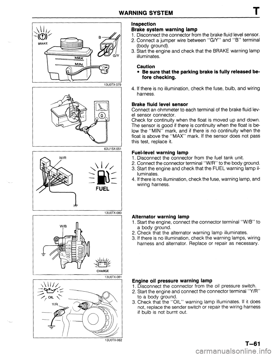
Inspection
Brake system warning lamp
1. Disconnect the connector from the brake fluid level sensor.
2. Connect a jumper wire between “G/Y” and “6” terminal
(body ground).
3. Start the engine and check that the BRAKE warning lamp
illuminates.
Caution
l Be sure that the parking brake is fully released be-
fore checking.
4. If there is no illumination, check the fuse, bulb, and wiring
harness.
Brake fluid level sensor
Connect an ohmmeter to each terminal of the brake fluid lev-
el sensor connector.
Check for continuity when the float is moved up and down.
The sensor is good if there is continuity when the float is be-
low the “MIN” mark, and if there is no continuity when the
float is above the “MAX” mark. If the sensor does not pass
this test, replace it.
Fuel-level warning lamp
1. Disconnect the connector from the fuel tank unit.
2. Connect the connector terminal “W/R” to the body ground.
3. Start the engine and check that the FUEL warning lamp il-
luminates.
4. If there is no illumination, check the fuse, warning lamp, and
wiring harness.
Alternator warning lamp
1. Start the engine, connect the connector terminal “W/B” to
a body ground.
2. Check that the alternator warning lamp illuminates.
3. If there is no illumination, check the warning lamps, wiring
harness and alternator. Replace or repair as necessary.
Engine oil pressure warning lamp
1. Disconnect the connector from the oil pressure switch.
2. Start the engine and connect the connector terminal “Y/R”
to a body ground.
3. Check that the “OIL” warning lamp illuminates. If it does
not, replace the sender switch or repair the wiring harness
if bulb is not burnt out.
T-61
Page 918 of 1164
T
I WARNING SYSTEM
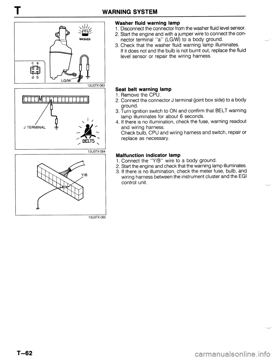
Washer fluid warning lamp
1. Disconnect the connector from the washer fluid level sensor.
2. Start the engine and with a jumper wire to connect the con-
nector terminal “a” (LGIW) to a body ground.
3. Check that the washer fluid warning lamp illuminates.
If it does not and the bulb is not burnt out, replace the fluid
level sensor or repair the wiring harness.
13UOTX-08
_-
1 /
J TERMINAL -
13UOTX-08
13UOTX-08
Seat belt warning lamp
1, Remove the CPU.
2. Connect the connector J terminal (joint box side) to a body
ground.
3. Turn ignition switch to ON and confirm that BELT warning
lamp illuminates for about 6 seconds.
4. If there is no illumination, check the fuse, warning readout
and wiring harness.
Check bulb, CPU and wiring harness and switch, repair or
replace as necessary.
Malfunction indicator lamp
1, Connect the “Y/B” wire to a body ground.
2. Start the engine and check that the warning lamp illuminates.
3. If there is no illumination, check the meter fuse, bulb, and
wiring harness between the instrument cluster and the EGI
control unit.
T-62
Page 922 of 1164
T INSTRUMENT CLUSTER
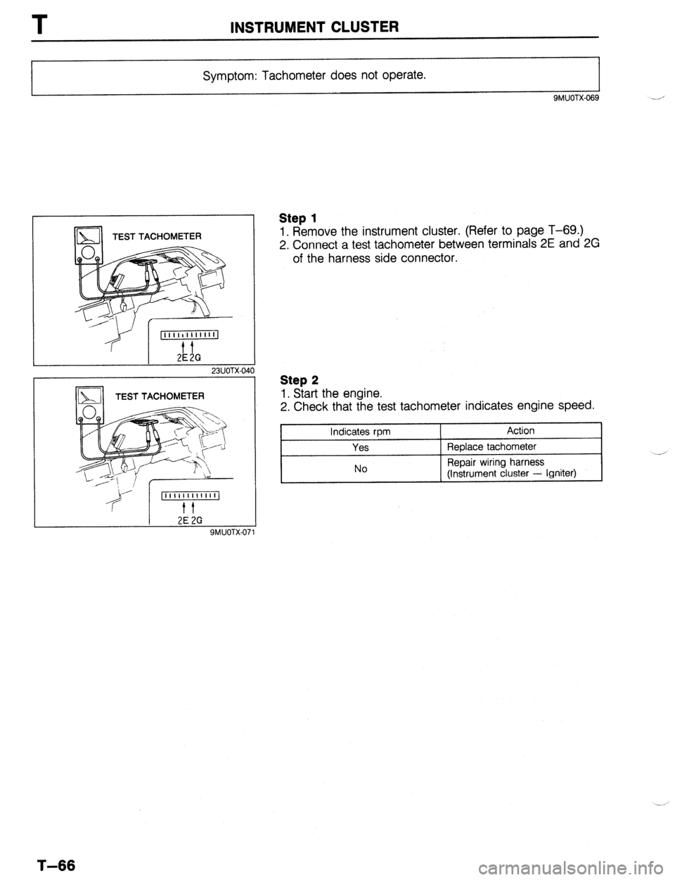
Symptom: Tachometer does not operate.
9MUOTX.069
TEST TACHOMETER
23UOTX-040
2E 2G SMUOTX-01
Step 1
1. Remove the instrument cluster. (Refer to page T-69.)
2. Connect a test tachometer between terminals 2E and 2G
of the harness side connector.
Step 2
1. Start the engine.
2. Check that the test tachometer indicates engine speed.
Indicates rpm
Yes
No Action
Replace tachometer
Repair wiring harness
(Instrument cluster - Igniter)
T-66
Page 927 of 1164
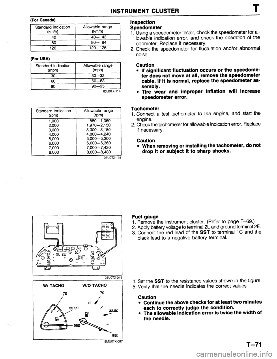
INSTRUMENT CLUSTER T
(For Canada)
(For USA)
11
OSUOTX-114
Standard Indication
(rpm)
1,000
2,000
3,000
4,000
5,000
6,000
7,000
8,000 Allowable range
@pm)
880-l ,060
1,970-2,150
3,000-3,180
4,000-4,240
5,000-5,300
6,000-6,360
7.000-7.420
8:600-8:480
03UOTX-11 5
I 23UOTX-044 WI TACHO WIO MACHO
32.50
ssn
9MUOTX-087
Inspection
Speedometer
1. Using a speedometer tester, check the speedometer for ai-
lowable indication error, and check the operation of the
odometer. Replace if necessary.
2. Check the speedometer for fluctuation and/or abnormal
noise.
Caution
l If significant fluctuation occurs or the speedome-
ter does not move at all, remove the speedometer
cable. If it is normal, replace the speedometer as-
sembly.
l Tire wear and improper inflation will Increase
speedometer error.
Tachometer
1. Connect a test tachometer to the engine, and start the
engine.
2. Check the tachometer for allowable indication error. Replace
if necessary.
Caution
l When removing or installing the tachometer, do not
drop it or subject it to sharp shocks.
Fuel gauge
1. Remove the instrument cluster. (Refer to page T-69.)
2. Apply battery voltage to terminal 2L and ground terminal 2E.
3. Connect the red lead of the
SST to terminal 1C and the
black lead to a negative battery terminal.
4. Set the
SST to the resistance values shown in the figure.
5. Verify that the needle indicates the correct values.
Caution
l Continue the above checks for at least two minutes
each to correctly judge the condition.
l The allowable indication error is twice the width of
the needle.
T-71
Page 941 of 1164
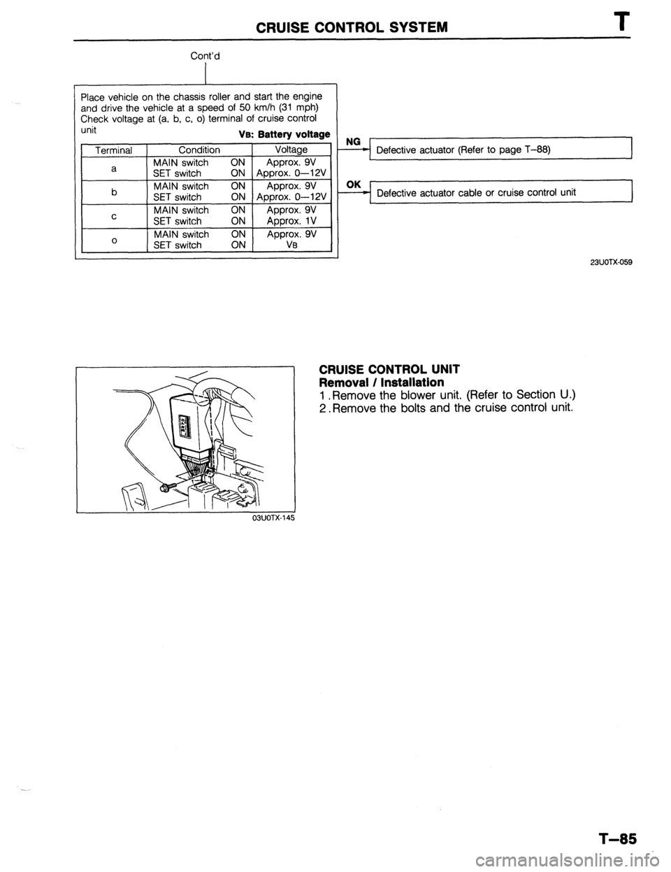
CRUISE CONTROL SYSTEM T
Cont’d
Place vehicle on the chassis roller and start the engine
and drive the vehicle at a speed of 50 km/h (31 mph)
Check voltage at (a, b, c, o) terminal of cruise control
unit Va: Battery voltage
Terminal Condition Voltage
MAIN switch ON
a Approx. 9V
SET switch
ON Approx. 0-12V
b MAIN switch ON Approx. 9V
SET switch ON Approx. 0-12V
MAIN switch ON
C Approx. 9V
SET switch ON
Approx. 1V
0 MAIN switch
Approx. 9V
SET switch Va
OBUOTX
Defective actuator (Refer to page T-88) I
Defective actuator cable or cruise control unit
23UOTX-059
CRUISE CONTROL UNIT
Removal / Installation
1 .Remove the blower unit. (Refer to Section U.)
2. Remove the bolts and the cruise control unit.
T-85
Page 960 of 1164

C
b l HEATER 6 AIR CONDITIONER 1 G
MAIN
I3 Fl
AD FAN
JB-06
4
B/R (F)
1,
1 I
t
G-07
REAR WIPER
IOA
-L/G (F) _fcoJI)
a-07
63
ENGINE
CONTROL UNIT
(SECTION 6-1~. 2bl A/C SWITCH 6 BLOWER SWITCH ILLUMINATION
LAMPS’REFER TO SECTION I-4
RESISTOR ASSEMBLY L/B
-1
r
BjG L)B
(AC9 (AC)
4NT
A/C SWITCH -L/B
4)
6 33
;~~l-bJG FAN
(SECTION B-3.
i-01 CONDENSER FAN (AC) -03 DIODE (AC) G-04 REFRIGERANT G-05 REFRIGERANT G-06 MAGNETIC CLUTCH (AC) G-07 IE) - (AC) CONNECTOR
PRESSURE SWITCH NO.2 (AC) PRESSURE SWITCH NO. 1 (AC)
I I I I
s-10 A/C SWITCH(ACl G-12 BLOWER MOTOR (F) G-13 RESISTOR ASSEMBLY (II
I
I j-14 BLOWER SWITCH (I)
Page 964 of 1164
TROUBLESHOOTING GUIDE
Symptom: Condenser fan does not operate. (Magnetic clutch operates normally.)
03uoux-009
I 23UOlJX-007
WITH
MTX AND
fi==Tl (B/O)...BP ENGINE
-’ WITH ATX
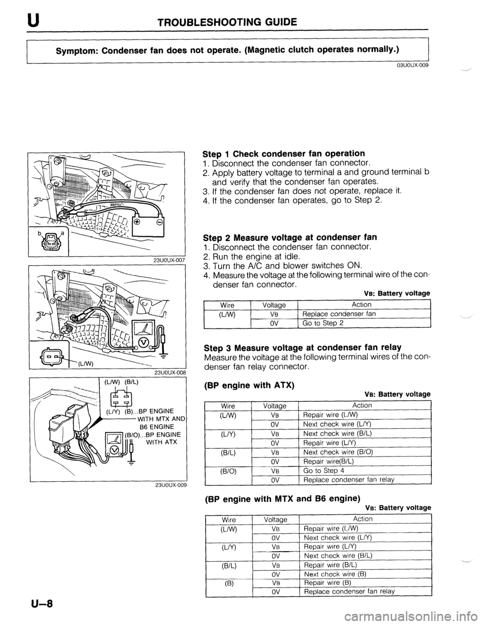
Step 1 Check condenser fan operation
1. Disconnect the condenser fan connector.
2. Apply battery voltage to terminal a and ground terminal b
and verify that the condenser fan operates.
3. If the condenser fan does not operate, replace it.
4. If the condenser fan operates, go to Step 2.
Step 2 Measure voltage at condenser fan
1. Disconnect the condenser fan connector.
2. Run the engine at idle.
3. Turn the A/C and blower switches ON.
4. Measure the voltage at the following terminal wire of the con-
denser fan connector.
VB: Battery voltage
Wire
WV Voltage
VB
ov Action -
Replace condenser fan
Go to Step 2
Step 3 Measure voltage at condenser fan relay
Measure the voltage at the following terminal wires of the con-
denser fan relay connector.
(BP engine with ATX)
VB: Battery voltage
(BP engine with MTX and 66 engine)
Ve: Battery voltage
Wire Voltage Action
o-/W) VI3 Repair wire (L/W)
ov Next check wire (L/Y)
VY) VB Repair wire (L/Y)
ov Next check wire (B/L)
VW VB Repair wire (B/L)
ov Next check wire (B)
03 Va Repair wire (B)
ov Replace condenser fan relay ,
U-8