MAZDA PROTEGE 1992 Workshop Manual
Manufacturer: MAZDA, Model Year: 1992, Model line: PROTEGE, Model: MAZDA PROTEGE 1992Pages: 1164, PDF Size: 81.9 MB
Page 701 of 1164

WHEELS AND TIRES
OUTLINE ..................................................
SPECIFICATIONS ....................................
TROUBLESHOOTING
GUIDE.. .................... Q- 2
WHEELS AND TIRES ................................. Q- 3
SPECIAL NOTES ABOUT WHEELS
AND TIRES .......................................... Q- 3
NOTES REGARDING TIRE REPLACEMENT. Q- 3
INSPECTION I ADJUSTMENT.. .................. Q- 3
REMOVAL / INSTALLATION.. .................... Q- 6
TIRE ROTATION .....................................
WHEEL BALANCE ADJUSTMENT ............. :: ;
13UOQX-001
Page 702 of 1164
Q OUTLINE, TROUBLESHOOTING GUIDE
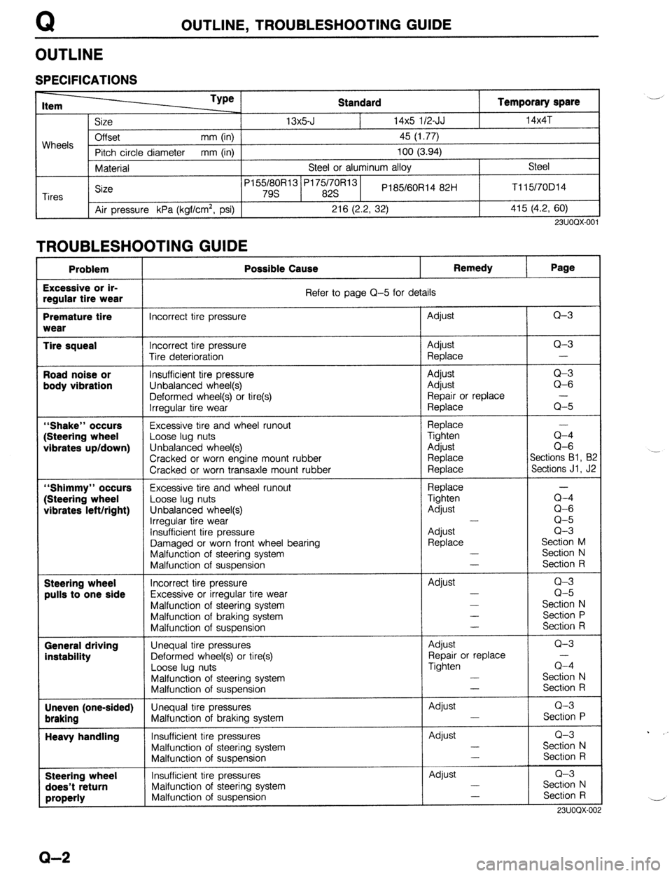
OUTLINE
SPECIFICATIONS
Wheels
Tires Standard Temporary spare __/
Size 13x5-J 14x5 l/2-JJ l4x4T
Offset mm (in)
45 (1.77)
Pitch circle diameter mm (in)
100 (3.94)
Material Steel or aluminum alloy Steel
Size P155/80R13’P175/70R131
PI 85/60Rl4 82H Tll5/70D14
79s 82s
Air pressure kPa (kgflcm’, psi)
216 (2.2, 32) 415 (4.2, 60)
23UOQX-001
TROUBLESHOOTING GUIDE _____ -_- ____ _ __.- -. -.-.--
Problem Possible Cause Remedy Page
Excessive or ir-
regular tire wear Refer to page Q-5 for details
Premature tire incorrect tire pressure Adjust Q-3
wear
Tire squeal Incorrect tire pressure Adjust Q-3
Tire deterioration Replace -
Road noise or Insufficient tire pressure Adjust Q-3
body vibration
Unbalanced wheel(s) Adjust Q-6
Deformed wheel(s) or tire(s) Repair or replace
Irregular tire wear Replace Q-5
“Shake” occurs Excessive tire and wheel runout
Replace
(Steering wheel Loose lug nuts
Tighten a-4
vibrates up/down) Unbalanced wheel(s)
Adjust Q-6
Cracked or worn engine mount rubber
Replace Sections Bl, B:
Cracked or worn transaxle mount rubber
Replace Sections Jl, J2
“Shimmy” occurs Excessive tire and wheel runout
Replace
(Steering wheel
Loose lug nuts Tighten a-4
vibrates left/right) Unbalanced wheel(s)
Adjust Q-6
irregular tire wear -
Q-5
insufficient tire pressure
Adjust Q-3
Damaged or worn front wheel bearing
Replace Section M
Malfunction of steering system -
Section N
Malfunction of suspension -
Section R
Steering wheel Incorrect tire pressure Adjust Q-3
pulls to one side Excessive or irregular tire wear -
Q-5
Malfunction of steering system -
Section N
Malfunction of braking system -
Section P
Malfunction of suspension -
Section R
General driving Unequal tire pressures Adjust Q-3
instability Deformed wheel(s) or tire(s) Repair or replace
Loose lug nuts Tighten Q-4
Malfunction of steering system -
Section N
Malfunction of suspension -
Section R
Uneven (one-sided) Unequal tire pressures
Adjust Q-3
braking Malfunction of braking system -
Section P
Heavy handling Insufficient tire pressures Adjust Q-3
Malfunction of steering system -
Section N
Malfunction of suspension -
Section R
Steering wheel Insufficient tire pressures Adjust Q-3
does’t return Malfunction of steering system -
Section N
properly Malfunction of suspension -
Section R
731100x-or . _. -,
Q-2
Page 703 of 1164
WHEELS AND TIRES
WHEELS AND TIRES
SPECIAL NOTES ABOUT WHEELS AND TIRES
1. Do not use wheels or tires other than the specified types.
2. Aluminum wheels are easily scratched. When washing them, use a soft cloth, never a wire brush. If the
vehicle is steam cleaned, do not allow boiling water to contact the wheels.
3. If alkaline compounds (such as saltwater or road salts) get on aluminum wheels, wash them as soon as
possible to prevent damage. Use only a neutral detergent.
9MUOQX-004
NOTES REGARDING TIRE REPLACEMENT
Note the following points when tires are to be removed from or mounted onto the wheels.
1. Be careful not to damage the tire bead, the rim bead, or the edge of the rim.
2. Use a wire brush, sandpaper, or cloth to clean and remove all rust and dirt from the rim edge and the
rim bead.
3. When cleaning aluminum wheels, use a soft cloth, never a wire brush or sandpaper.
4. Remove any pebbles, glass, nails, and other foreign items embedded in the tire tread.
5. Be sure the air valve is installed correctly.
6. Apply a soapy solution to the tire bead and the edge of the rim.
7. After mounting a tire onto a wheel, inflate the tire to 250-300 kPa (2.55-3.06 kg/cm2, 35.55-42.66
psi). Check to be sure that the bead is seated correctly onto the rim and that there are no air leaks. Then
reduce the pressure to the specified level.
8. If a tire iron is used to change a tire on an aluminum wheel, be sure to use a piece of rubber between
the iron lever and the wheel to avoid damage to the wheel. Work should be done on a rubber mat, not
on a hard or rough surface.
03UOQX-004
23UOOX-003
TIRE
I
AIR VALVE
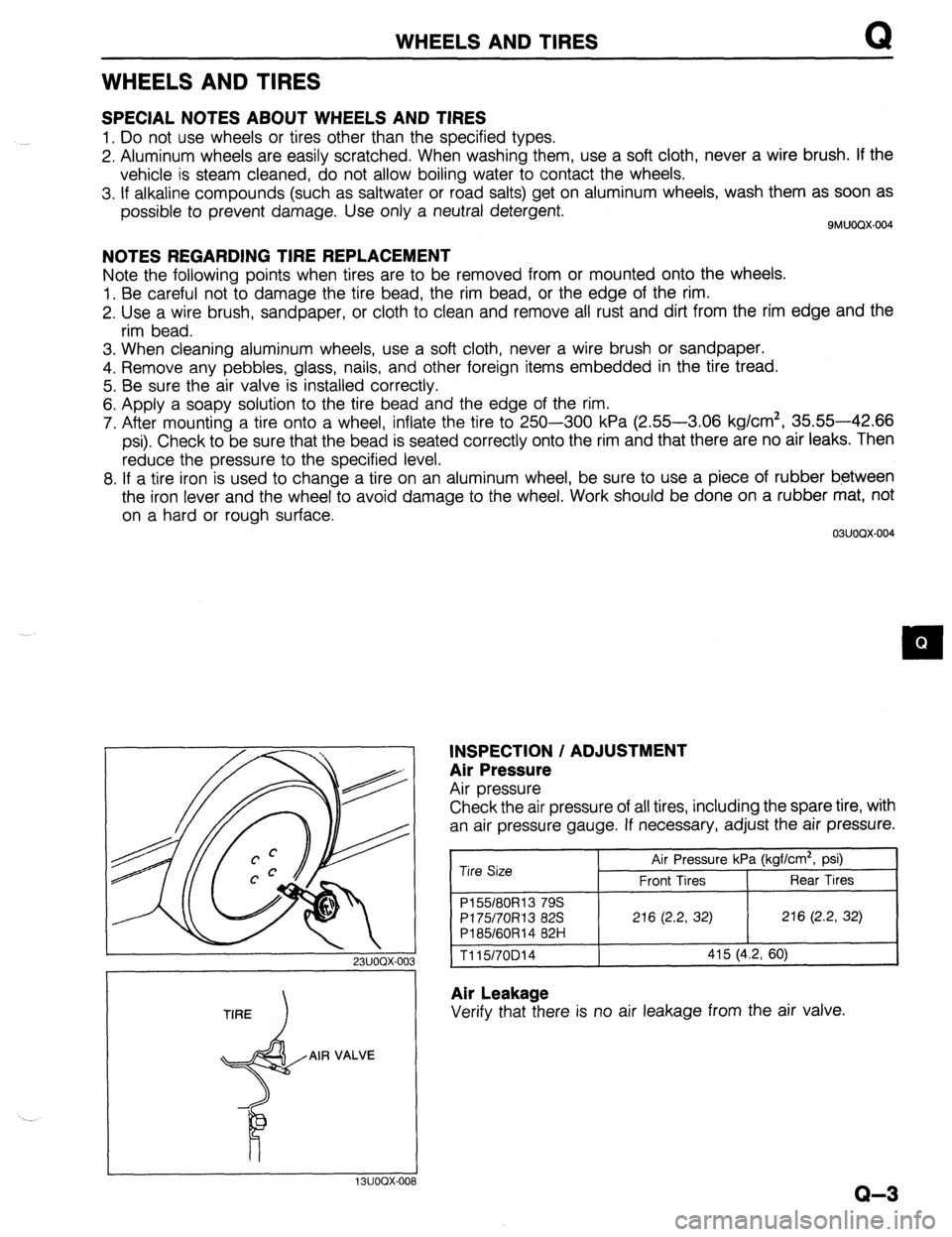
INSPECTION / ADJUSTMENT
Air Pressure
Air pressure
Check the air pressure of all tires, including the spare tire, with
an air pressure gauge. If necessary, adjust the air pressure.
Tire Size Air Pressure kPa (kgf/cm2, psi)
Front Tires Rear Tires
P155180R13 79s
PI 75/70R13 82s 216 (2.2, 32) 216 (2.2, 32)
P185/60R14 82H
1115/70D14 415 (4.2, 60)
Air Leakage
Verify that there is no air leakage from the air valve.
I I 13UOOX-008
Q-3
Page 704 of 1164

WHEELS AND TIRES
WEAR INDICATOR WEAR IbiDICATOR
13UOQX-00s
13UOQX-011 0
23UOQX-004
Tire Wear
1. Check the remaining tread.
Remaining tread
Standard tires: 1.6mm (0.063 in) min.
Snow tires: 50% of tread ’ _,I’
2. The tire should be replaced if the wear indicators are
exposed.
Inspection (Tire and Wheel)
The wheel or tire should be replaced if any crack, damage,
deformation or other problem is found.
Wheel and Tire Runout
1. Jack up the vehicle and place it on safety stands.
2. Set the probe of a dial indicator against the wheel, and meas-
ure the runout through one full revolution.
Runout:
_..’
Horizontal Aluminum wheel: 2.0 (0.079), Steel wheel: 2.5 (0.098)
Vertical 1.5 (0.059)
3. Replace the wheel if necessary.
Caution
l Adjust wheel balance after replacement of a wheel
or tire.
Lug Nut
1. Verify that the lug nuts are tightened to the specified torque.
Tightening torque:
66-l 16 N*m (9-12 m-kg, 65-67 ft-lb)
Q-4
Page 705 of 1164
WHEELS AND TIRES
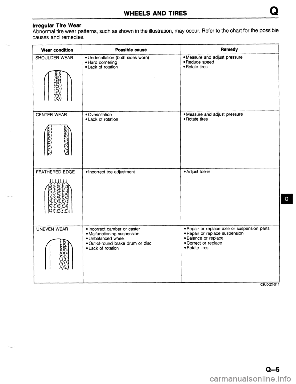
Irregular Tire Wear
Abnormal tire wear patterns, such as shown in the illustration, may occur. Refer to the chart for the possible
causes and remedies.
Wear condition
SHOULDER WEAR Possible cause l Underinflation (both sides worn) l Hard cornering l Lack of rotation Remedy
l Measure and adjust pressure l Reduce speed l Rotate tires
CENTER WEAR
l Overinflation l Lack of rotation *Measure and adjust pressure l Rotate tires
FEATHERED EDGE
l Incorrect toe adjustment l Adjust toe-in
UNEVEN WEAR
l Incorrect camber or caster l Malfunctioning suspension l Unbalanced wheel
*Out-of-round brake drum or disc
l Lack of rotation *Repair or replace axle or suspension parts
l Repair or replace suspension l Balance or replace
*Correct or replace
l Rotate tires
03UOQX-01
Q-5
Page 706 of 1164

WHEELS AND TIRES
L 13UOQX-005
FRONT
13UOQX-006
G=a I) OUTSIDE
BALANC
WEIGHT
REMOVAL / INSTALLATION
1. The wheel-to-hub contact surfaces must be clean.
2. Tighten the lug nuts to the specified torque.
Tightening torque:
88-l 18 N-m (9-12 m-kg, 85-87 ft-lb)
Caution
l When reinstalling a wheel, retighten the lug nuts to
the specified torque after about 1,000 km (820 miles)
driving.
TIRE ROTATION
To prolong tire life and assure uniform tire wear, rotate the tires
from every 3,000 km (1,860 miles) to every 6,000 km (3,720
miles).
Caution
l Do not include “TEMPORARY USE ONLY” spare tire
in rotation.
l Use the best tires on the front axle.
l After rotating the tires, adjust each tire to the speci-
fied air pressure. (Refer to page Q-3.)
WHEEL BALANCE ADJUSTMENT
If a wheel becomes unbalanced or if a tire is replaced or
repaired, the wheel must be rebalanced to within specification.
Maximum unbalance (at rim edge)
13 inch wheel: 11 g (0.39 oz)
14 inch wheel: 10 g (0.35 or)
Caution
l Do not use more than two balance weights on the
inner or outer side of the wheel.
l If the total weight exceeds 1OOg (3.5 oz) perslde,
rebalance after moving the tire around on the rim.
l Attach the balance weights tightly on the wheel.
l Select suitable balance weights for steel or alumi-
num alloy wheels.
l Do not use an on-car balancer on automatic trans-
axle models; it may cause transaxle damage.
.__’
Q-6
Page 707 of 1164
R
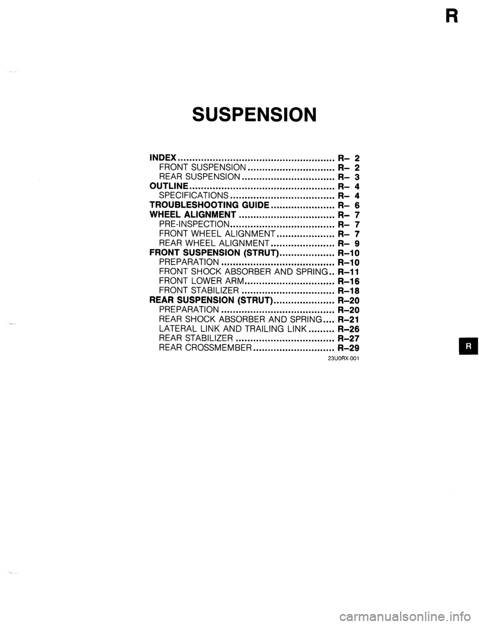
SUSPENSION
INDEX ...................................................... R- 2
FRONT SUSPENSION ..............................
R- 2
REAR SUSPENSION ................................ R- 3
OUTLINE .................................................. R- 4
SPECIFICATIONS ....................................
TROUBLESHOOTING GUIDE.. .................... ;I ;
WHEEL ALIGNMENT ................................. R- 7
PRE-INSPECTION ....................................
FRONT WHEEL ALIGNMENT.. .................. ;I ;
REAR WHEEL ALIGNMENT.. .................... R- 9
FRONT SUSPENSION (STRUT). .................. R-l 0
PREPARATION ....................................... R-l 0
FRONT SHOCK ABSORBER AND SPRING . . R-11
FRONT LOWER ARM
............................... R-l 6
FRONT STABILIZER ................................
R-l 6
REAR SUSPENSION (STRUT). .................... R-20
PREPARATION ....................................... R-20
REAR SHOCK ABSORBER AND SPRING .... R-21
LATERAL LINK AND TRAILING LINK.. ....... R-26
REAR STABILIZER .................................. R-27
REAR CROSSMEMBER ............................ R-29
23UORX-001
Page 708 of 1164
R INDEX
INDEX
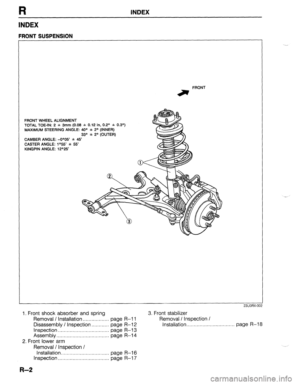
FRONT WHEEL ALIGNMENT
TOTAL TOE-IN: 2 -1: 3mm (0.08 f 0.12 in, 0.2’ * 0.3’)
MAXIMUM STEERING ANGLE: 40=’ * 2’ (INNER)
33“ f 2O (OUTER)
CAMBER ANGLE: -O”05’ * 45’
CASTER ANGLE: lo55 f 55
KINGPIN ANGLE: 12“25 FRONT
irr
FRONT SUSPENSION
1. Front shock absorber and spring
Removal I Installation . . . . . . . . . . . . . . . . . . page R-l 1
Disassembly / Inspection . . . . . . . . . . . . page R-l 2
Inspection . . . . . . . . . . . . . . . . . . . . . . . . . . . . . . . . page R-l 3
Assembly . . . . . . 1 . . . . . . . . . . . . . . . . . . . . . . . . . . . . . page R-l 4
2. Front lower arm
Removal / Inspection I
Installation ,,...,.......,...........,.._..,. page R-l 6
Inspection . . . . . . . . . . . . . . . . . . . . . . . . . . . . . . . . . . . page R-l 7
R-2
3. Front stabilizer
Removal / Inspection /
Installation, . . . . . . ,. . . . . . . . . . . . . . . . . . . . . . . . . page R-l 8
Page 709 of 1164
INDEX
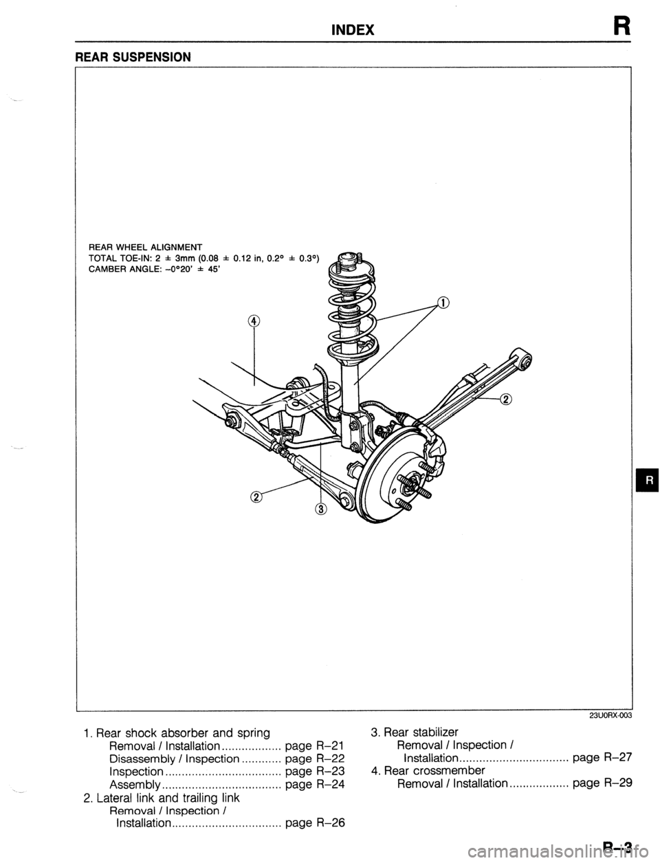
REAR WHEEL ALIGNMENT
TOTAL TOE-IN: 2 f 3mm (0.08 f 0.12 in, 0.2O * 0.39
CAMBER ANGLE: -O”20’ * 45’
m
1. Rear shock absorber and spring 3. Rear stabilizer
Removal / Installation . . . . . . . . . . . . . . . . . . page R-21 Removal / Inspection /
Disassembly / Inspection . . . . . . . . . . . . page
R-22 Installation . . . . . . . . . . . . . . . . . . . . . . . . . . ...*... page R-27
Inspection . . . . . . . . . . . . . . . . . . . . . . . . . . . . . . . . . . . page R-23 4. Rear crossmember
Assembly.. . . . . . . . . . . . . . . . . . . . . . . . . . . . . . . . . . .
page R-24 Removal I Installation. . . . . . . . . . . . . . . . . . page R-29
2. Lateral link and trailing link
Removal / Inspection /
Installation . . . . . . . . . . . . . . . . . . . . . . . . . . . . . . . . . page R-26
Page 710 of 1164
R OUTLINE
OUTLINE
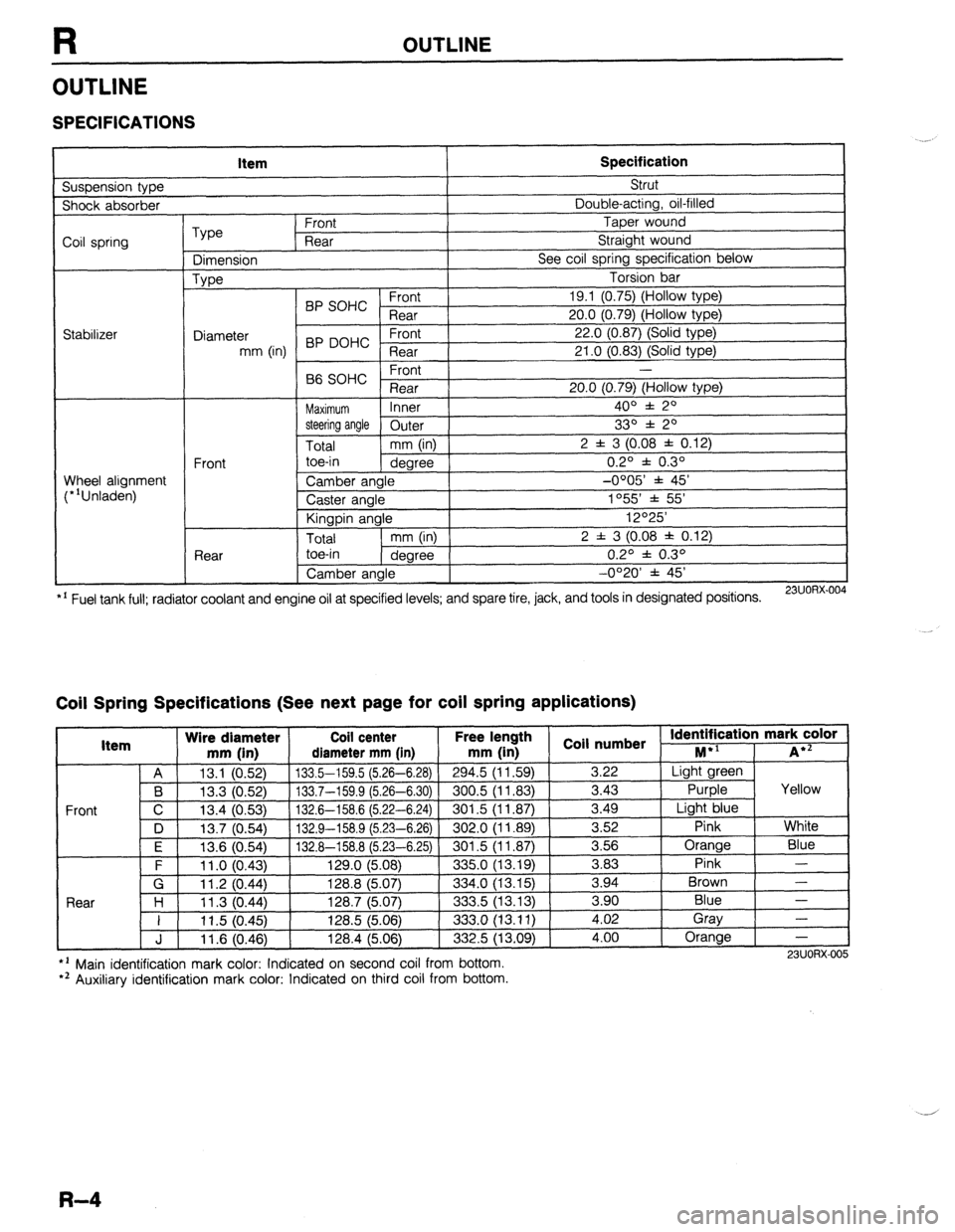
SPECIFICATIONS
Suspension type Item Specification Strut
Shock absorber Double-acting, oil-filled
Coil spring
Stabilizer Type Front Taper wound
Rear Straight wound
Dimension See coil spring specification below
Type Torsion bar
BP SOHC Front 19.1 (0.75) (Hollow type)
Rear 20.0 (0.79) (Hollow type)
Diameter 22.0 (0.87) (Solid type)
mm (in) BP DOHC ;eTrt
21 .O (0.83) (Solid type)
P ,
-
66 SOHC rronr
Rear 20.0 (0.79) (Hollow type)
Maximum Inner 400 f 20
steering angle
Outer 330 f 20
Total mm (in) 2 f 3 (0.08 f 0.12)
Front toe-in
degree 0.2O f 0.3O
Wheel alignment
(*‘Unladen) Camber angle -0005’ f 45’
Caster angle 1055 * 55’
Kingpin angle 12O25’
Total mm (in) 2 f 3 (0.08 * 0.12)
Rear toe-in
degree 0.2O f 0.3O
Camber angle -0°20’ f 45’
*’ Fuel tank full; radiator coolant and engine oil at specified levels; and spare tire, jack, and tools in designated positions.
23UORX.004
Coil Spring Specifications (See next page for coil spring applications)
I Item Wire diameter Coil center Free lel.=-. .
mm iin1 rliamotor mm [in mm (in 1 coil numbs
Front
nath
1 _ . . *St Identification mark color +l
., . . . . I...,
-*.....-.“, * . . . . . ,..-, -....- I--‘, M iA*=
A 13.1 (0.52) 133.5-159.5 (5.26-6.28)
294.5 (11.59) 3.22 Light green
B 13.3 (0.52) 133.7-159.9 (5.26-6.30) 300.5 (11.83)
3.43 Purple Yellow
C 13.4 (0.53)
132.6-158.6 (5.22-6.24) 301.5 (11.87) 3.49
Light blue
D 13.7 (0.54)
132.9-158.9 (5.23-6.26) 302.0 (11.89) 3.52
Pink White
I F I 12f3 Kl5Al I 1.17 A-l!% 8 f!i PR-Fi 751
I RrIl .5 II 1 6x71 I 3.56 Orange
Blue
3 83 Pink -
Brown - .“._ \“.- .,
. “W.., ~ - -. - \-. -- -. - -, -- .-
\’ .‘-‘I t
F 11 .o (0.43) 129.0 (5.08)
335.0 (13.19) -.--
G 11.2 (0.44) 128.8 (5.07)
334.0 (13.15) 3.94
Rnnr l-4
1 I ? 07 AA 1387 /5n7
.?m !i 113 1% 3 an Blue - I I I I .” \v.-7, I&V., \V.“., ---.., \.-. .-, I 11.5 (0.45) 128.5 (5.06)
333.0 (13.11) i:oi Gray
-
J 11.6 (0.46) 128.4 (5.06)
332.5 (13.09) 4.00 Orange
-
l ’ Main identification mark color: Indicated on second coil from bottom.
*’ Auxiliary identification mark color: Indicated on third coil from bottom. 23UORX-005
R-4