MITSUBISHI SPYDER 1990 Service Manual PDF
Manufacturer: MITSUBISHI, Model Year: 1990, Model line: SPYDER, Model: MITSUBISHI SPYDER 1990Pages: 2103, PDF Size: 68.98 MB
Page 61 of 2103
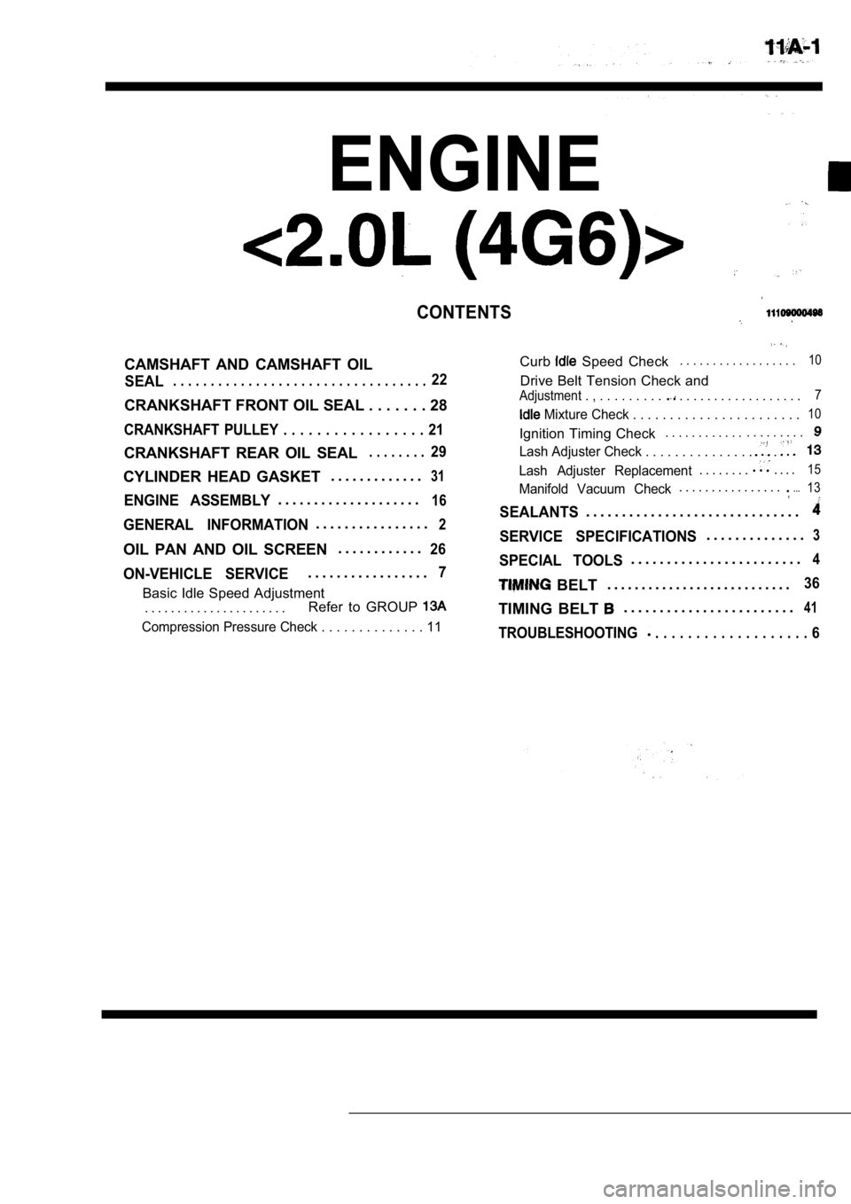
ENGINE
CONTENTS
CAMSHAFT AND CAMSHAFT OIL
SEAL. . . . . . . . . . . . . . . . . . . . . . . . . . . . . . . . . .22
CRANKSHAFT FRONT OIL SEAL . . . . . . . 28
CRANKSHAFT PULLEY . . . . . . . . . . . . . . . . . 21
CRANKSHAFT REAR OIL SEAL. . . . . . . .29
Curb Speed Check. . . . . . . . . . . . . . . . . .10
Drive Belt Tension Check and
Adjustment . , . . . . . . . . . . . . . . . . . . . . . . . . . . . 7
Mixture Check . . . . . . . . . . . . . . . . . .
. . . . .10
Ignition Timing Check. . . . . . . . . . . .. . . . . . . . .
Lash Adjuster Check . . . . . . . . . . . . . . . .
CYLINDER HEAD GASKET . . . . . . . . . . . . .31
ENGINE ASSEMBLY. . . . . . . . . . . . . . . . . . . .16
GENERAL INFORMATION. . . . . . . . . . . . . . . .2
OIL PAN AND OIL SCREEN . . . . . . . . . . . .26
ON-VEHICLE SERVICE. . . . . . . . . . . . . . . . .7
Basic Idle Speed Adjustment
. . . . . . . . . . . . . . . . . . . . . . Refer to GROUP
Lash Adjuster Replacement. . . . . . . .. . . .15
Manifold Vacuum Check. . . . . . . . . . . . . . . ....13
SEALANTS. . . . . . . . . . . . . . . . . . . . . . . . . . . . . .
SERVICE SPECIFICATIONS. . . . . . . . . . . . . .3
SPECIAL TOOLS. . . . . . . . . . . . . . . . . . . . . . . .4
BELT. . . . . . . . . . . . . . . . . . . . . . . . . . .36
TIMING BELT . . . . . . . . . . . . . . . . . . . . . . . .41
Compression Pressure Check . . . . . . . . . . . .
. . 11TROUBLESHOOTING . . . . . . . . . . . . . . . . . . . 6
Page 62 of 2103
ENGINE General Information
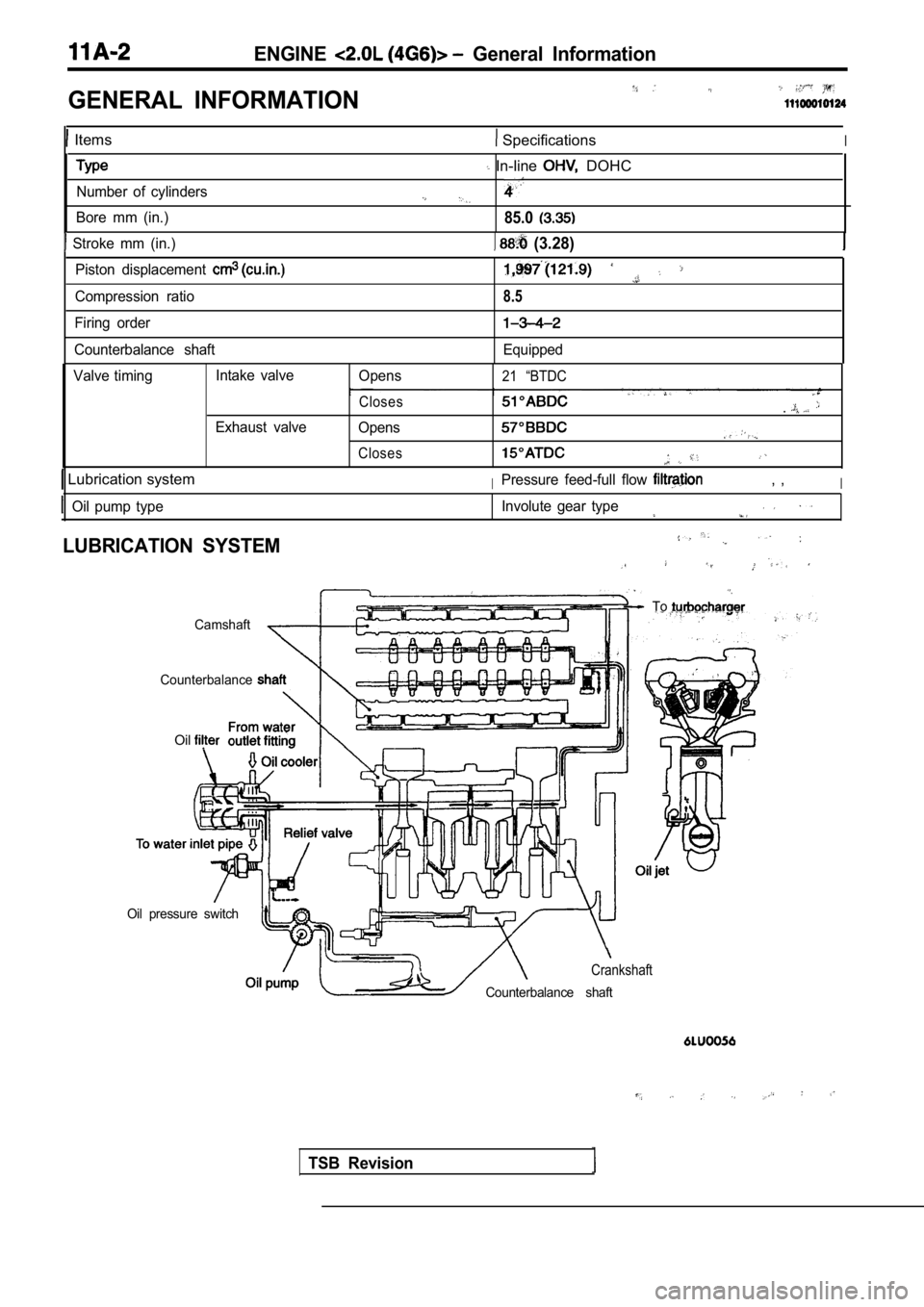
GENERAL INFORMATION
Items SpecificationsI
Number of cylinders
Bore mm (in.)
Stroke mm (in.)
In-line DOHC
85.0
(3.28)
Piston displacement
Compression ratio
Firing order
Counterbalance shaft8.5
Equipped
Valve timing Intake valve
Exhaust valve Opens
Closes
Opens
Closes 21 “BTDC
.
Lubrication systemIPressure feed-full flow , ,I
Oil pump type
LUBRICATION SYSTEM
Involute gear type
To
Camshaft
Counterbalance
TSB Revision
Oil
Oil pressure switch
Crankshaft
Counterbalance shaft
Page 63 of 2103
ENGINE Service Specifications
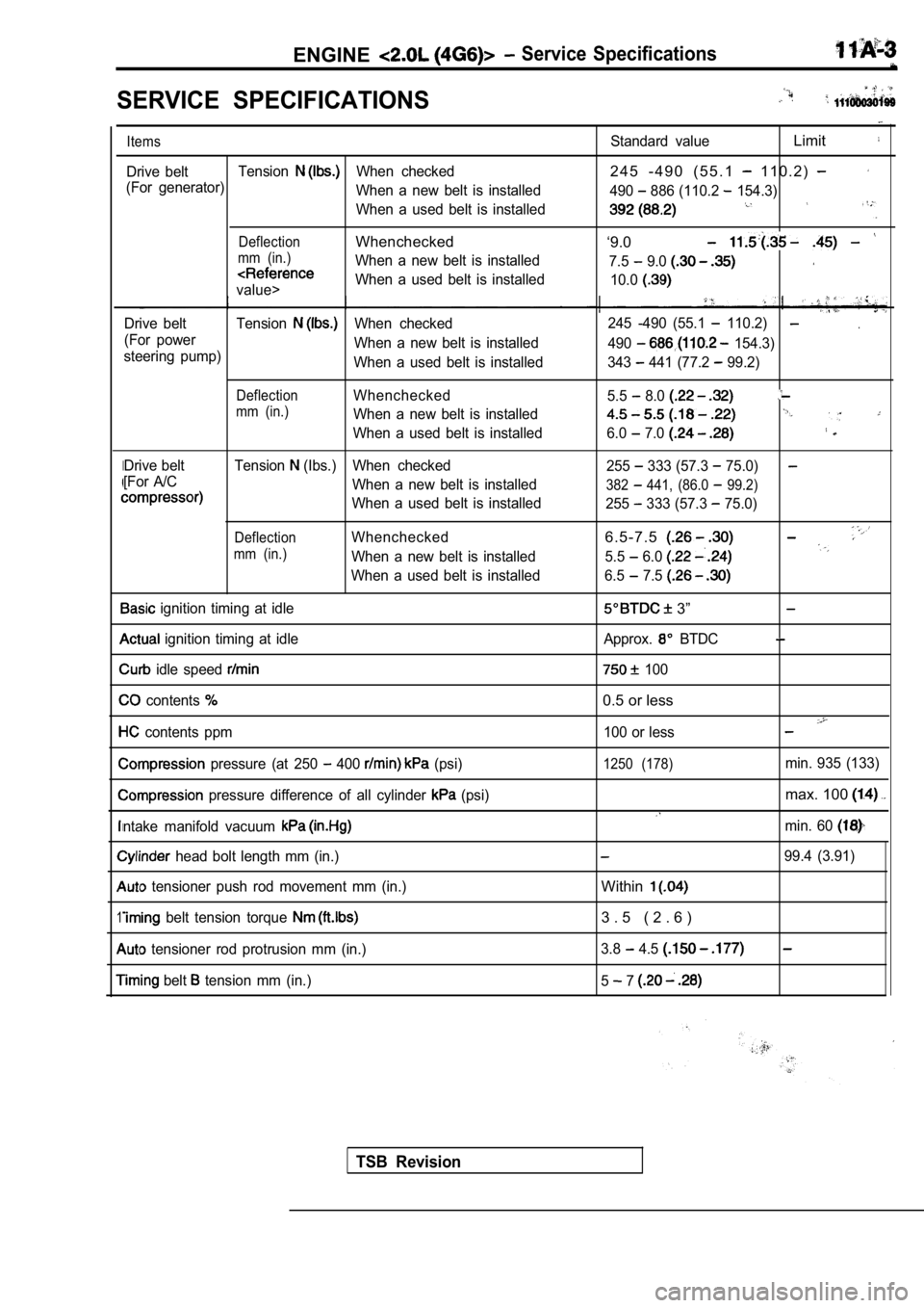
SERVICE SPECIFICATIONS
I
1
Items
Drive beltTensionWhen checked
(For generator) When a new belt is installed
When a used belt is installed
DeflectionWhenchecked
mm (in.)When a new belt is installed
value>When a used belt is installed
Drive belt Tension
When checked
(For power When a new belt is installed
steering pump) When a used belt is installed
DeflectionWhenchecked
mm (in.)When a new belt is installed
When a used belt is installed
Drive belt Tension
(Ibs.) When checked
[For A/C When a new belt is installed
When a used belt is installed
DeflectionWhenchecked
mm (in.)When a new belt is installed
When a used belt is installed
ignition timing at idle
ignition timing at idle
idle speed
contents
contents ppm
pressure (at 250 400 (psi)
pressure difference of all cylinder (psi)
ntake manifold vacuum
head bolt length mm (in.)
tensioner push rod movement mm (in.)
belt tension torque
tensioner rod protrusion mm (in.)
belt tension mm (in.)
Standard valueLimit
2 4 5 - 4 9 0 ( 5 5 . 1 1 1 0 . 2 )
490 886 (110.2 154.3)
‘9.0
7.5 9.0
10.0
.245 -490 (55.1 110.2)
490 154.3)
343
441 (77.2 99.2)
5.5
8.0
6.0 7.0
255 333 (57.3 75.0)
382 441, (86.0 99.2)
255 333 (57.3 75.0)
6 . 5 - 7 . 5
5.5 6.0
6.5 7.5
3”
Approx. BTDC
100
0.5 or less
100 or less
1250 (178)min. 935 (133)
max. 100
min. 60
99.4 (3.91)
Within
3 . 5 ( 2 . 6 )
3.8 4.5
5 7
TSB Revision
Page 64 of 2103
ENGINE
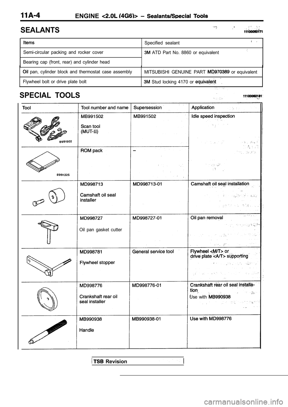
SEALANTS
Semi-circular packing and rocker cover
Bearing cap (front, rear) and cylinder head Specified sealant ATD Part No. 8860 or equivalent
pan, cylinder block and thermostat case assembly
MITSUBISHI GENUINE PART or equivalent
Flywheel bolt or drive plate bolt Stud locking 4170 or .
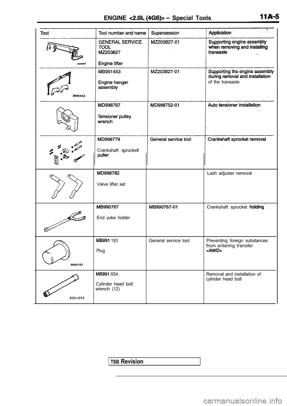
SPECIAL TOOLS
Oil pan gasket cutter
Use with
Revision
Page 65 of 2103
ENGINE Special Tools
of the transaxle
Crankshaft sprocket
Lash adjuster removal
Valve lifter set
. .
End yoke holder
Crankshaft sprocket
193General service tool Preventing foreign substances
from entering transfer
Plug
654
Cylinder head bolt
wrench (12) Removal and installation of
cylinder head bolt
TSB Revision
Page 66 of 2103
ENGINE,
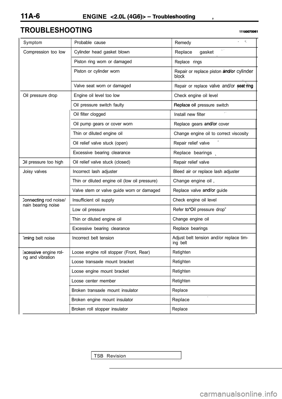
TROUBLESHOOTING
Oil filter cloggedInstall new filter
Oil pump gears or cover wornReplace gears cover
Thin or diluted engine oil Change engine oil to correct viscosity
Oil relief valve stuck (open) Repair relief valve
Excessive bearing clearanceReplace bearings
pressure too high Oil relief valve stuck (closed) Repair relief valve
Joisy valves Incorrect lash adjuster Bleed air or rep lace lash adjuster
Thin or diluted engine oil (low oil pressure)
Change engine oil ,
Valve stem or valve guide worn or damaged Replace va lve guide
rod noise/Insufficient oil supplyCheck engine oil level
nain bearing noise Low oil pressure Refer
pressure drop”
Thin or diluted engine oil Change engine oil
Excessive bearing clearance Replace bearings
belt noiseIncorrect belt tension Adjust belt tension and/or replace tim-ing belt
engine Loose engine roll stopper (Front, Rear)Retighten
ng and vibration
Loose transaxle mount bracketRetighten
Loose engine mount bracketRetighten
Loose center memberRetighten
Broken transaxle mount insulatorReplace
Broken engine mount insulatorReplace
Broken roll stopper insulatorReplace
Symptom
Probable cause
Remedy.
Compression too low Cylinder head gasket blownReplace gasket
Piston ring worn or damagedReplace rings
Piston or cylinder worn
Repair or replace piston cylinder
block
Valve seat worn or damagedRepair or replace valve and/or
Oil pressure drop Engine oil level too low Check engine oil level
Oil pressure switch faulty
pressure switch
TSB Revision
Page 67 of 2103
ENGINE On-vehicle
98 (22
Generator
pulley
pulley
v
pulley
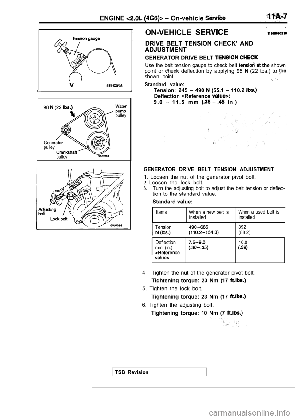
ON-VEHICLE
DRIVE BELT TENSION CHECK’ AND
ADJUSTMENT
GENERATOR DRIVE BELT
Use the belt tension gauge to check belt the shown
point or deflection by applying 98 (22 tbs.) to
shown point.
Standard value:
Tension: 245 490 (55.1 110.2
Deflection
GENERATOR DRIVE BELT TENSION ADJUSTMENT
1. Loosen the nut of the generator pivot bolt.
2. Loosen the lock bolt.
3.Turn the adjusting bolt to adjust the belt tension or deflec-
tion to the standard value.
Standard value:
ItemsWhen a new belt is
installed
Whena used belt is
installed
Tension392
(88.2)I
Deflection10.0
mm (in.)
4Tighten the nut of the generator pivot bolt.
Tightening torque: 23 Nm (17
5. Tighten the lock bolt.
Tightening torque: 23 Nm (17
6. Tighten the adjusting bolt.Tightening torque: 10 Nm (7
TSB Revision
Page 68 of 2103
ENGINE On-vehicle Service
pump pulley
Cranksh
pulley
pulley
a
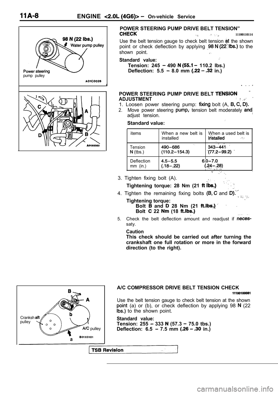
POWER STEERING PUMP DRIVE BELT TENSION”
11100110114
Use the belt tension gauge to check belt tension the shown
point or check deflection by applying to the
shown point.
Standard value:
Tension: 245 490 110.2 Ibs.)
Deflection: 5.5
8.0 mm in.)
.
POWER STEERING PUMP DRIVE BELT
ADJUSTMENT
1. Loosen power steering pump: bolt (A,
2.Move power steering tension belt moderately
adjust tension.
Standard value:
items
Tension
(tbs.)
Deflection
mm (in.)
When a new belt is When a used belt is installed
,,
3. Tighten fixing bolt (A).
Tightening torque: 28 Nm (21
4. Tighten the remaining fixing bolts and
Tightening torque:
Bolt and 28 Nm (21
Bolt 22 (18
5.Check the belt deflection amount and readjust if
saty.
Caution
This check should be carried out after turning the
crankshaft one full rotation or more in the forward
direction (to the right).
A/C COMPRESSOR DRIVE BELT TENSION CHECK
Use the belt tension gauge to check belt tension at the shown
(a) or (b), or check deflection by applying 98 (22
to the shown point.
Standard value:
Tension: 255 333 (57.3 75.0 tbs.)
Deflection: 6.5
7.5 mm in.)
Page 69 of 2103
ENGINE On-vehicle
A/C COMPRESSOR DRIVE BELT TENSION ADJUSTMENT
1. Loosen tension pulley fixing bolt A.
2. Adjust belt tension with adjusting bolt B.
Standard value:
Items
Tension
(Ibs.)
Deflection
When a new belt isWhen a used belt is
installedinstalled
382-411255-333
6.5-7.5
3. Tighten fixing nut A.
Tightening torque: 23-26 Nm
4.Check the belt deflection and readjust if neces-
sary.
Caution
This check should be carried out after turning the
crankshaft one full rotation or more in the forward
direction (to the right).
IGNITION TIMING CHECK
1.Before inspection and adjustment set vehicle in the follow-
ing condition.
lEngine coolant temperature:
lLights, electric cooling fan and all accessories: OFF
lTransaxle: Neutral (P range on vehicles with
2. Turn the ignition switch to OFF and connect the scan
tool to the data link connector.
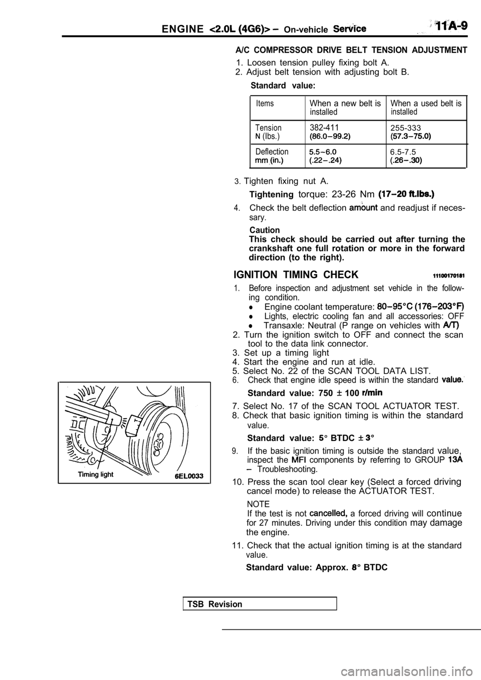
3. Set up a timing light
4. Start the engine and run at idle.
5. Select No. 22 of the SCAN TOOL DATA LIST.
6.Check that engine idle speed is within the standard
Standard value: 750 100
7. Select No. 17 of the SCAN TOOL ACTUATOR TEST.
8. Check that basic ignition timing is within the standard
value.
Standard value: BTDC
9.If the basic ignition timing is outside the standar d value,
inspect the components by referring to GROUP
Troubleshooting.
10. Press the scan tool clear key (Select a forced driving
cancel mode) to release the ACTUATOR TEST.
NOTE
If the test is not
a forced driving will continue
for 27 minutes. Driving under this condition may damage
the engine.
11. Check that the actual ignition timing is at the standard
value.
Standard value: Approx. BTDC
TSB Revision
Page 70 of 2103
ENGINE On-vehicle Service
NOTE
1.Ignition timing is variable within about even under
operating.
2. And it is automatically further advanced by abou t
from BTDC at higher altitudes.
CURB IDLE SPEED CHECK
1. Before inspection and adjustment, set vehicles in the
following condition.
lEngine coolant temperature:
lLights, electric cooling fan and all accessories: OFF
lTransaxle: Neutral (P range on vehicles with
2. Turn the ignition switch to OFF and connect the scan
tool to the data link connector.
3. Select No. 17 of the SCAN TOOL ACTUATOR TEST.
4. Check the basic ignition timing.
Standard
BTDC
5. Run the engine at idle for 2 minutes.
6. Select No. 22 of the SCAN TOOL DATA LIST.
7. Check the curb idle speed.
Standard value: 750
100
NOTE
The idle speed is controlled automatically by the i dle air
control system.
8. If the idle speed is outside the standard value, inspect
the components by referring to GROUP Trou-
bleshooting.
IDLE MIXTURE CHECK .
1.Before inspection, set in following
lEngine coolant temperature:
lLights, electric cooling fan all
lTransaxle: Neutral (P range on
2. Turn the ignition switch to OFF and, connect the scan
tool to the data link ,
3. Select No. 17 of the SCAN TOOL
4.Check that the basic ignition
value.
Standard value: BTDC
5. Run the engine 2,500 for 2 minutes.
6. Set the CO, HC tester.
7. Check the CO contents and the HC contents, at id le.
Standard value: CO contents: 0.5% or less
HC contents: 100 rpm or less
Revision