NISSAN ALMERA N15 1995 Service Manual
ALMERA N15 1995
NISSAN
NISSAN
https://www.carmanualsonline.info/img/5/57349/w960_57349-0.png
NISSAN ALMERA N15 1995 Service Manual
Trending: steering wheel adjustment, service interval, oil viscosity, coolant level, Thermo, water pump, torque
Page 121 of 1701
Sealring
REPAIR
FORCOMPONENT PARTS
Output Shaft,Output Gear,IdlerGear, Reduction
Pinion GearandBearing Retainer -Except
Model 34X81(Cont'd)
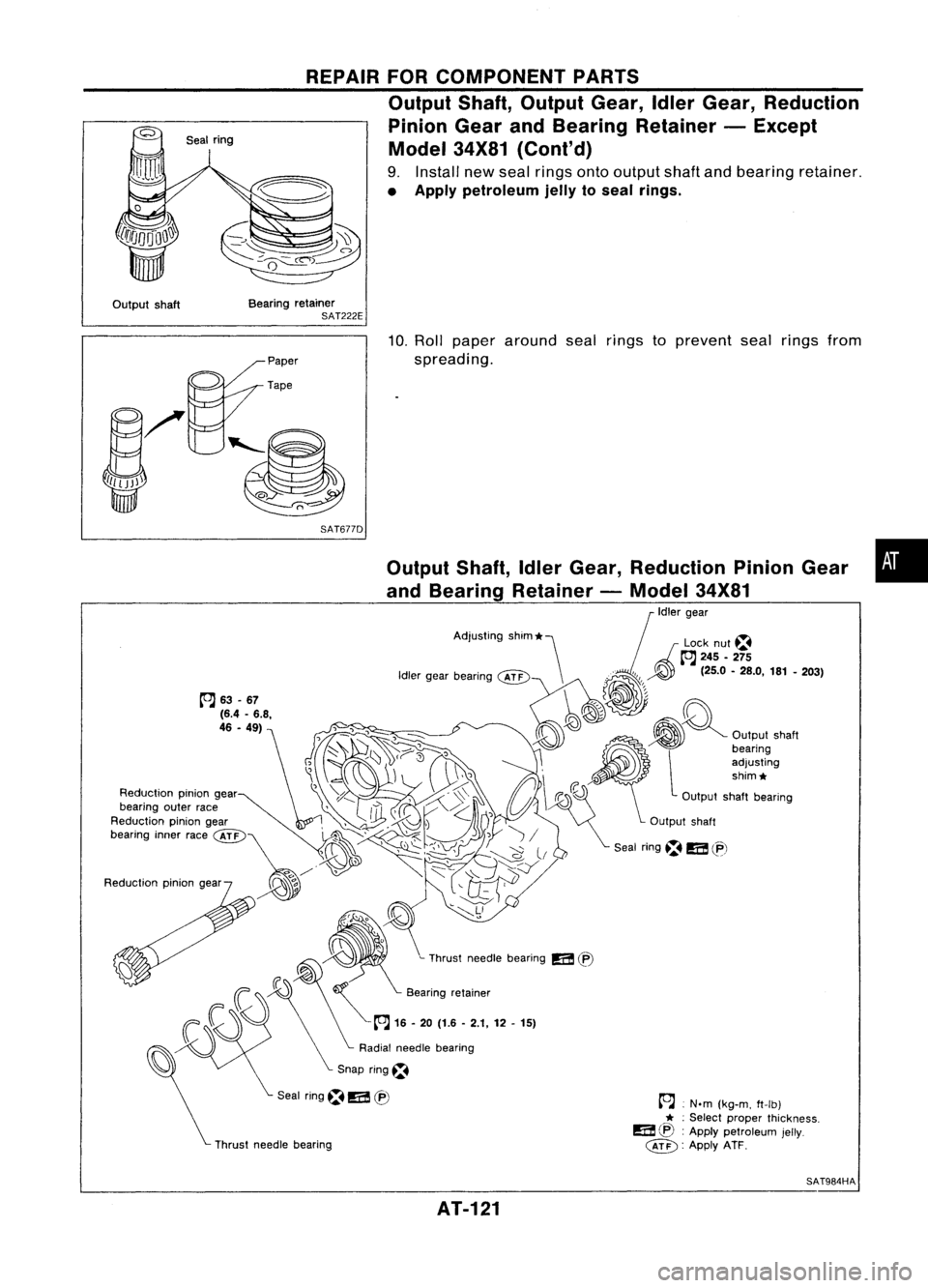
9. Install newseal rings ontooutput shaftandbearing retainer.
• Apply petroleum jellytoseal rings.
Output shaft Bearing
retainer
SAT222E
SAT677D
Thrust needle bearing
•
~ .N.m (kg-m, ft-Ib)
* :
Select proper thickness.
a ~:
Apply petroleum jelly.
@) :
Apply ATF.
~
Thrust needle beanng
!i:i!I
(EJ
10.
Roll paper around sealrings toprevent sealrings from
spreading.
Seal ring~
!i:i!I
tB
~63-67
(6.4 -6.8,
46 .49)
Reduclron piniongear
SAT984HA
AT-121
Page 122 of 1701
Sealring
~}~eal
~ nng
Output shaftbearing ~ REPAIR
FORCOMPONENT PARTS
Output Shaft,IdlerGear, Reduction PinionGear
and Bearing Retainer -Model 34X81(Cont'd)
DISASSEMBL Y
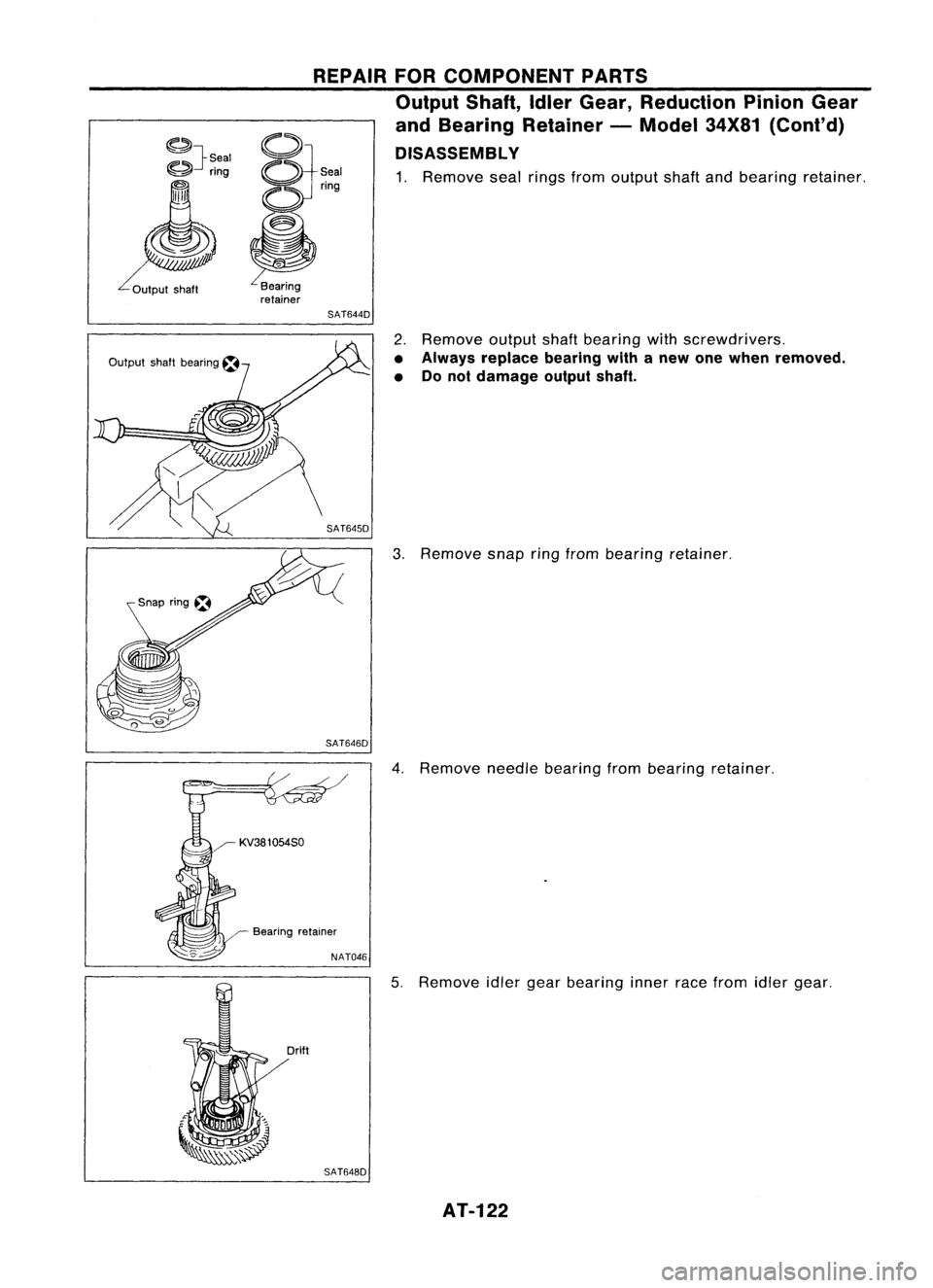
1. Remove sealrings fromoutput shaftandbearing retainer.
SAT644D
2.Remove outputshaftbearing withscrewdrivers.
• Always replace bearingwithanew onewhen removed.
• Donot damage outputshaft.
3. Remove snapringfrom bearing retainer.
SAT646D
4.Remove needlebearing frombearing retainer.
~ KV381054S0
Bearing retainer
NAT046
5.Remove idlergearbearing innerracefrom idlergear.
SAT648D AT-122
Page 123 of 1701
REPAIRFORCOMPONENT PARTS
Output Shaft,IdlerGear, Reduction PinionGear
and Bearing Retainer -Model 34X81(Cont'd)
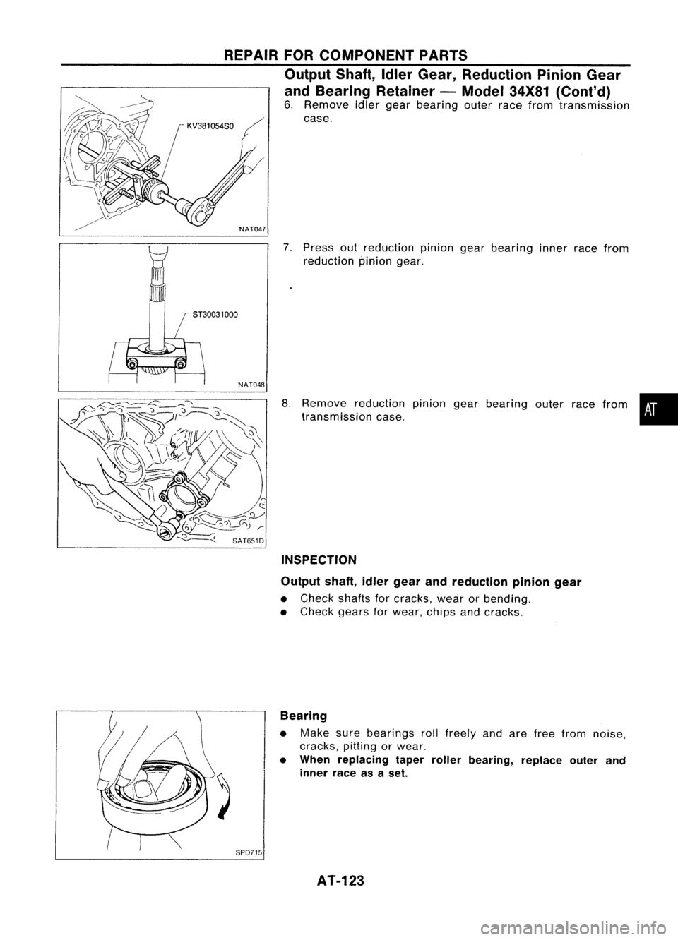
6. Remove idlergear bearing outerracefrom transmission
case.
NAT047
7.Press outreduction piniongearbearing innerracefrom
reduction piniongear.
8. Remove reduction piniongearbearing outerracefrom •
transmission case.
INSPECTION
Output shaft,idlergear andreduction piniongear
• Check shaftsforcracks, wearorbending.
• Check gearsforwear, chipsandcracks.
Bearing
• Make surebearings rollfreely andarefree from noise,
cracks, pittingorwear.
• When replacing taperroller bearing, replaceouterand
inner raceasaset
SPD715 AT-123
Page 124 of 1701
REPAIRFORCOMPONENT PARTS
Output Shaft,IdlerGear, Reduction PinionGear
and Bearing Retainer -Model 34X81(Cont'd)
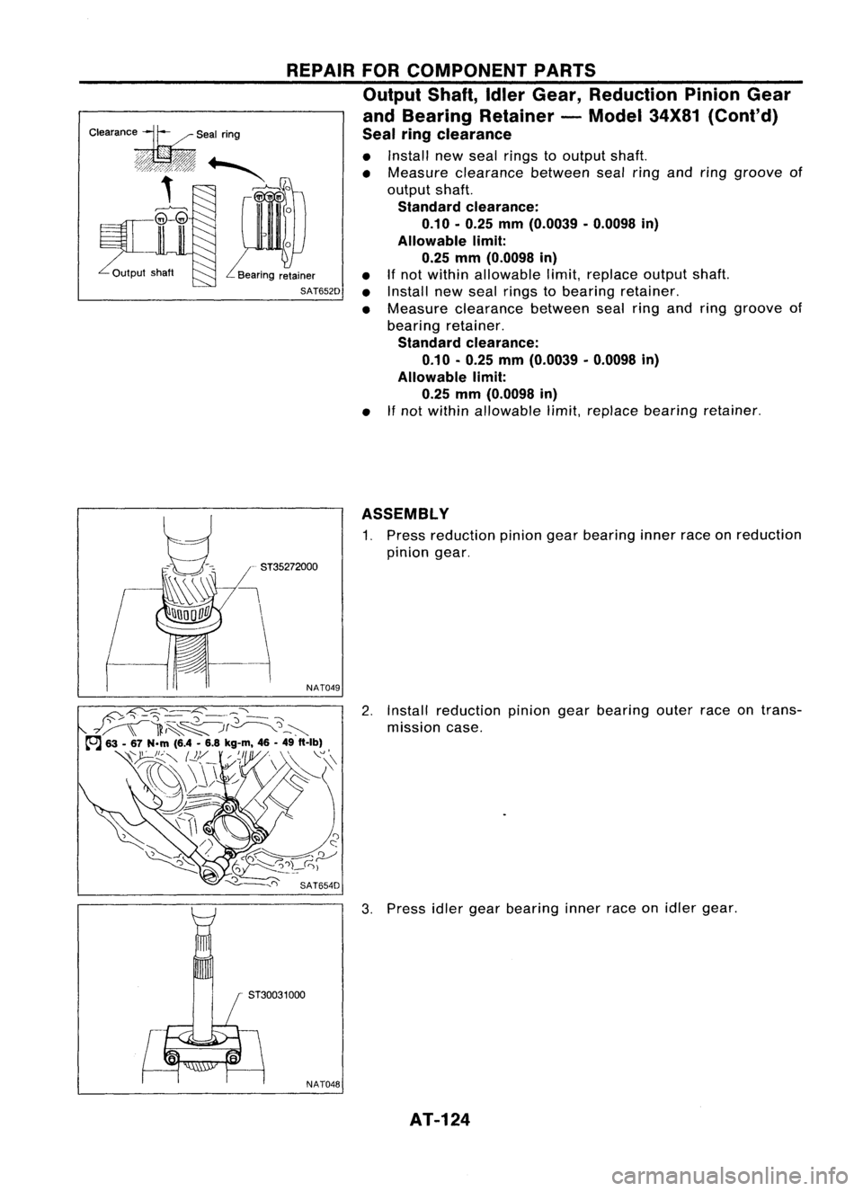
Seal ringclearance
............ •Install newseal rings tooutput shaft.
""""'" •Measure clearance betweensealringandring groove of
output shaft.
Standard clearance:
0.10.0.25 mm(0.0039 .0.0098 in)
Allowable limit:
0.25 mm(0.0098 in)
Bearing retainer •
Ifnot within allowable limit,replace outputshaft.
SAT652D •
Install newseal rings tobearing retainer.
• Measure clearance betweensealringandring groove of
bearing retainer.
Standard clearance:
0.10 .0.25 mm(0.0039 .0.0098 in)
Allowable limit:
0.25 mm(0.0098 in)
• If
not within allowable limit,replace bearing retainer.
ASSEMBLY
1. Press reduction piniongearbearing innerraceonreduction
pinion gear.
- ST35272000
NAT049
2.Install reduction piniongearbearing outerraceontrans-
mission case.
3. Press idlergear bearing innerraceonidler gear.
NAT048 AT-124
Page 125 of 1701
5T37830000
REPAIR
FORCOMPONENT PARTS
Output Shaft,IdlerGear, Reduction PinionGear
and Bearing Retainer -Model 34X81(Cont'd)
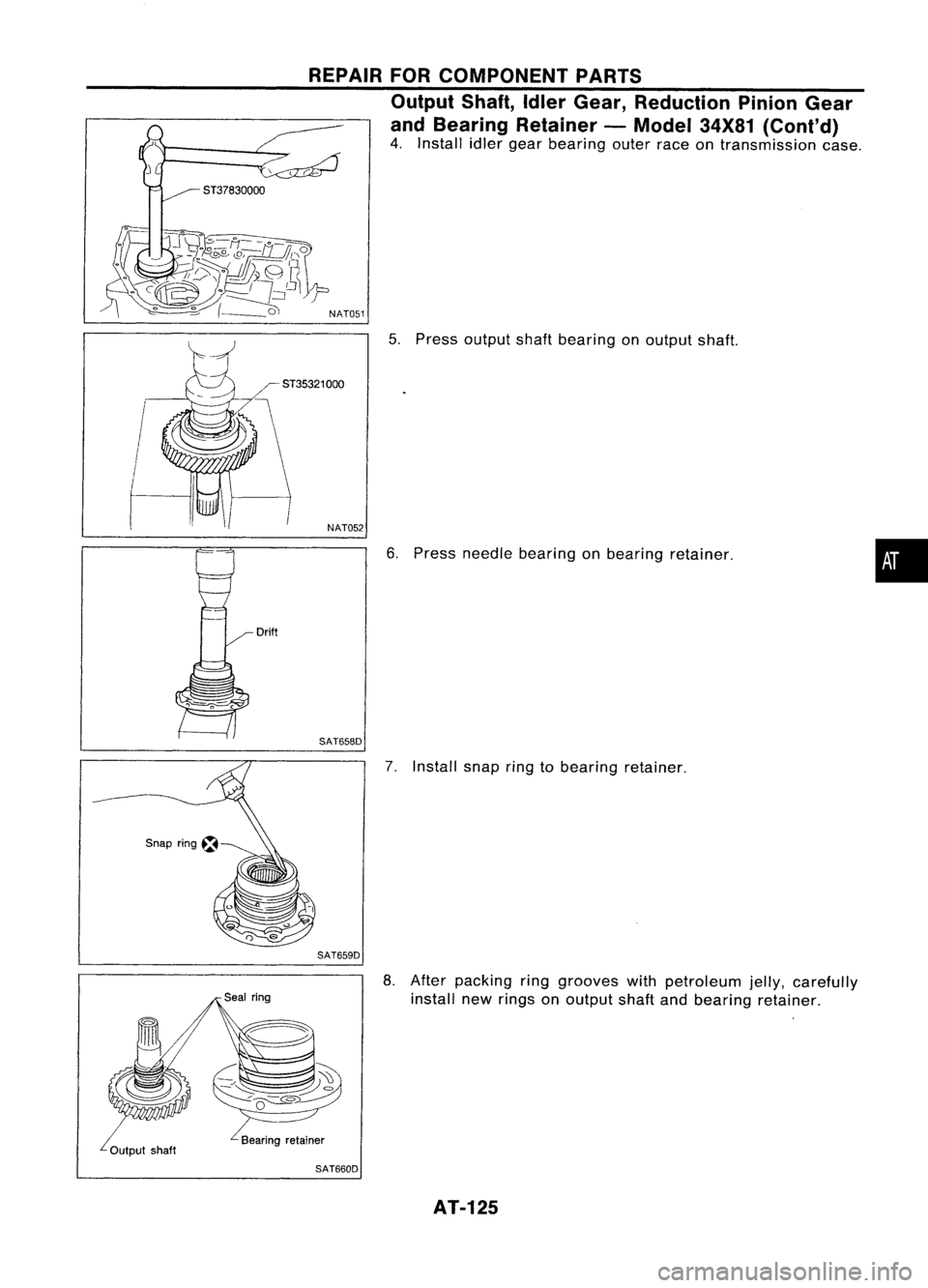
4. Install idlergear bearing outerraceontransmission case.
NAT051
5.Press output shaftbearing onoutput shaft.
NAT052
6.Press needle bearing onbearing retainer.
SAT658D
7.Install snapringtobearing retainer.
SAT659D
•
8. After packing ringgrooves withpetroleum jelly,carefully
install newrings onoutput shaftandbearing retainer.
SAT660D AT-125
Page 126 of 1701
REPAIRFORCOMPONENT PARTS
Output Shaft,IdlerGear, Reduction PinionGear
and Bearing Retainer -Model 34X81(Cont'd)
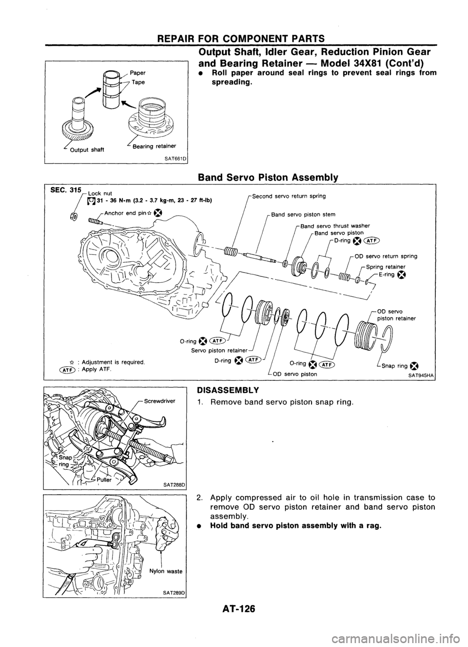
• Roll paper around sealrings toprevent sealrings from
spreading.
B:
paper
Tape
0/ ~
,~
~ SAT661D
n :
Adjustment isrequired.
cED:
ApplyATF. Band
Servo Piston Assembly
Second servoreturn spring
SAT945HA
DISASSEMBL Y
1. Remove bandservo piston snapring.
2. Apply compressed airtooil hole intransmission caseto
remove 00servo piston retainer andband servo piston
assembly.
• Hold band servo piston assembly witharag.
AT-126
Page 127 of 1701
REPAIRFORCOMPONENT PARTS
Band Servo Piston Assembly (Cont'd)
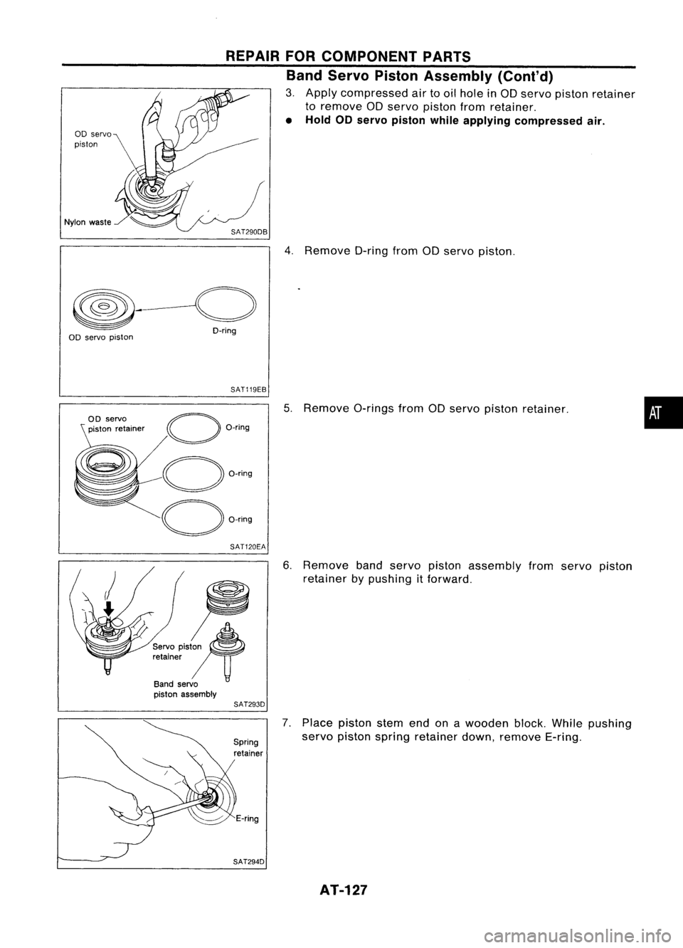
3. Apply compressed airtooil hole inaD servo piston retainer
to remove aDservo piston fromretainer.
• Hold 00servo piston whileapplying compressed air.
00 servo
piston
Nylon waste
4.Remove D-ringfromaDservo piston.
~~----o
O-ring
00 servo piston
SAT119EB
00 servo
piston retainer
SAT120EA
5.
Remove a-ringsfromaDservo piston retainer.
•
~;!
Servo
PiS' ~
retainer
IT
Band servo
piston assembly
SAT293D
6.
Remove bandservo piston assembly fromservo piston
retainer bypushing itforward.
7. Place piston stemendonawooden block.Whilepushing
servo piston spring retainer down,remove E-ring.
AT-127
Page 128 of 1701
SAT295DA
REPAIR
FORCOMPONENT PARTS
Band Servo Piston Assembly (Cont'd)
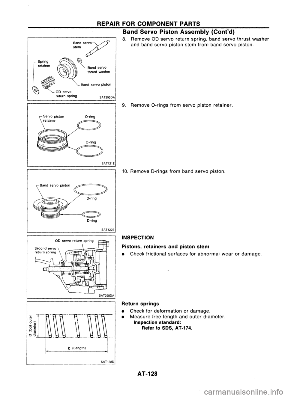
8. Remove aDservo return spring, bandservo thrust washer
and band servo piston stemfromband servo piston.
Band
servo~
stem ~
~~:~~r ~~ Bandservo
~ thrustwasher
~ Bandservo piston
~ ~OO servo
return spring
9.Remove a-ringsfromservo piston retainer.
SAT121E
10.Remove D-ringsfromband servo piston.
O-ring SAT122E INSPECTION
Pistons, retainers andpiston stem
• Check frictional surfacesforabnormal wearordamage.
Return springs
• Check fordeformation ordamage.
• Measure freelength andouter diameter.
Inspection standard:
Refer toSOS, AT-174.
Q
(Length)
SAT138D AT-128
Page 129 of 1701
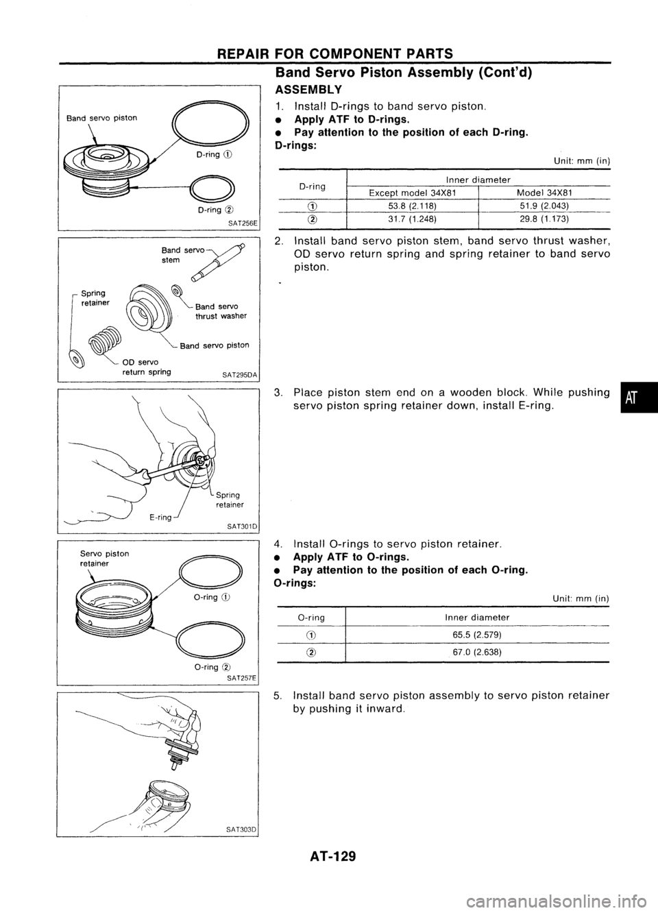
Unit:mm(in)
Inner diameter
O-ring Exceptmodel34X81 Model
34X81
G)
53.8
(2.118) 51.9(2.043)
@
31.7(1.248) 29.8
(1.173)
REPAIR
FORCOMPONENT PARTS
Band Servo Piston Assembly (Cont'd)
ASSEMBLY
1. Install D-rings toband servo piston.
• Apply ATF toO-rings.
• Pay attention tothe position ofeach O-ring.
O-rings:
O-ring
!IJ
SAT256E
O-ring
CD
o
Band
servo piston
BandservoW
stem?
~~:~~r ~~ Bandservo
~ .thrust washer
• .Band servo piston
~ ~ 00servo
return spring
SAT295DA
2.
Install bandservo piston stem,bandservo thrust washer,
OD servo return spring andspring retainer tabandservo
piston.
3. Place piston stemendonawooden block.Whilepushing •
servo piston spring retainer down,installE-ring.
SAT301D
4.Install O-rings toservo piston retainer.
• Apply ATFtoO-rings.
• Pay attention tothe position ofeach O-ring.
O-rings:
Servo
piston
retainer
a-ring
CD
O-ring
CD
@
Inner
diameter
65.5 (2.579)
67.0 (2.638) Unit:
mm(in)
a-ring
@
SAT257E
5.Install bandservo piston assembly toservo piston retainer
by pushing
it
inward.
SAT303D AT-129
Page 130 of 1701
REPAIRFORCOMPONENT PARTS
Band Servo Piston Assembly (Cont'd)
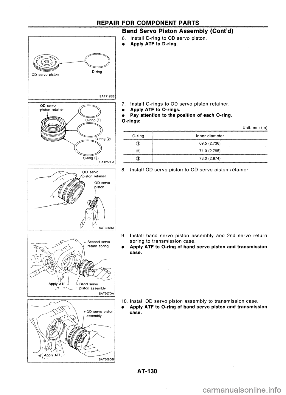
6. Install O-ring to00 servo piston.
• Apply ATFtoO-ring.
~---o
D-ring
aD servo piston
SAT119EB
7.Install a-rings toaD servo piston retainer.
• Apply ATFtoO-rings.
• Pay attention tothe position ofeach O-ring.
O-rings:
OD
servo
'piston retainer
a-ring
,j.,
SAT258EA
O-ring
Inner
diameter
69.5 (2.736)
71.0 (2.795)
73.0 (2.874)
Unit:
mm(in)
aD servo
piston
Second servo
return spring
jJ --,~
pistonassembly
SAT307DA
8.
Install aDservo piston to00 servo piston retainer.
9. Install bandservo piston assembly and2ndservo return
spring totransmission case.
• Apply ATFtoO-ring ofband servo piston andtransmission
case.
10.
Install aDservo piston assembly totransmission case.
• Apply ATFtoO-ring ofband servo piston andtransmission
case.
AT-130
Trending: jump start terminals, adding oil, oil dipstick, wiring, warning light, steering wheel, Motor oil
