NISSAN ALMERA N15 1995 Service Manual
Manufacturer: NISSAN, Model Year: 1995, Model line: ALMERA N15, Model: NISSAN ALMERA N15 1995Pages: 1701, PDF Size: 82.27 MB
Page 141 of 1701
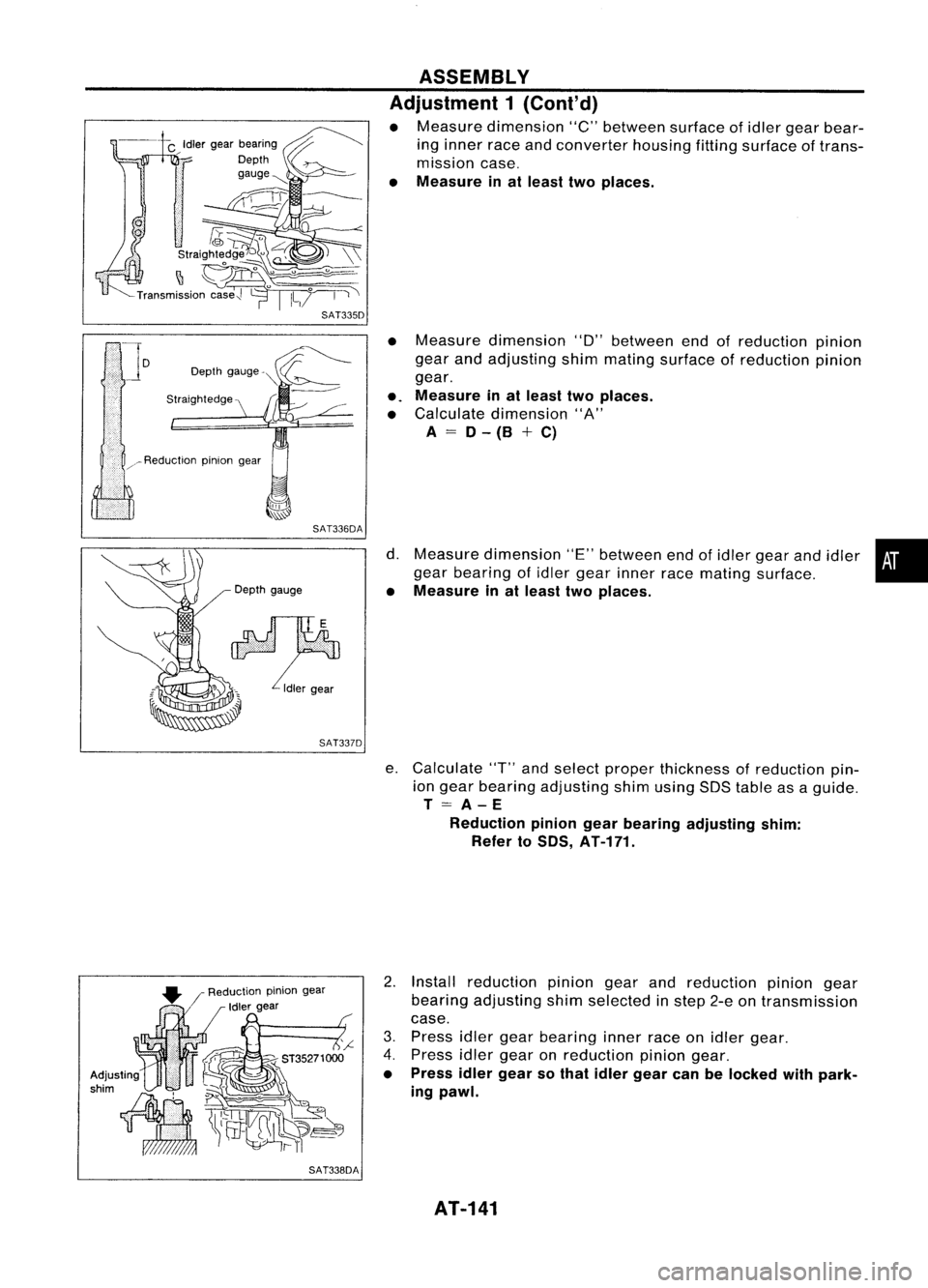
SAT336DA
Depth gauge
SAT337D
SAT338DA ASSEMBLY
Adjustment 1(Cont'd)
• Measure dimension "C"between surfaceofidler gear bear-
ing inner raceandconverter housingfittingsurface oftrans-
mission case.
• Measure inat least twoplaces.
• Measure dimension "D"between endofreduction pinIOn
gear andadjusting shimmating surface ofreduction pinion
gear .
•. Measure inat least twoplaces.
• Calculate dimension "A"
A = 0-(B +C)
d. Measure dimension "E"between endofidler gear andidler •
gear bearing ofidler gear inner racemating surface.
• Measure inat least twoplaces.
e. Calculate "T"andselect proper thickness ofreduction pin-
ion gear bearing adjusting shimusing SDStable asaguide.
T=A-E
Reduction piniongearbearing adjusting shim:
Refer to50S, AT-171.
2. Install reduction piniongearandreduction piniongear
bearing adjusting shimselected instep 2-eontransmission
case.
3. Press idlergearbearing innerraceonidler gear.
4. Press idlergear onreduction piniongear.
• Press idlergearsothat idler gear canbelocked withpark-
ing pawl.
AT-141
Page 142 of 1701
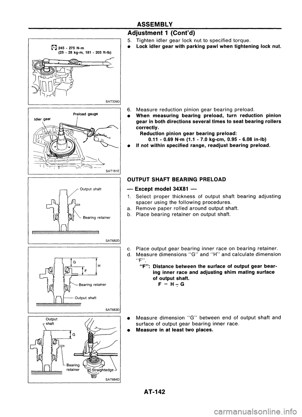
~245 -275 N.m
(25 -28 kg-m, 181-203 ft-Ib)
SAT339D ASSEMBLY
Adjustment 1(Cont'd)
5. Tighten idlergear locknuttospecified torque.
• Lock idlergear withparking pawlwhen tightening locknut.
Output shaft
Preload
gauge
Bearing retainer
6.
Measure reduction piniongearbearing preload.
• When measuring bearingpreload, turnreduction pinion
gear inboth directions severaltimestoseat bearing rollers
correctly. Reduction piniongearbearing preload:
0.11 -0.69 N.m(1.1.7.0 kg-em, 0.95•6.08 in-Ib)
• If
not within specified range,readjust bearingpreload.
OUTPUT SHAFTBEARING PRELOAD
- Except model34X81-
1. Select proper thickness ofoutput shaftbearing adjusting
spacer usingthefollowing procedures.
a. Remove paperrolledaround outputshaft.
b. Place bearing retainer onoutput shaft.
SAT682D
H
F
Output shaft
SAT683D
c.
Place output gearbearing innerraceonbearing retainer.
d. Measure dimensions "G"and"H" andcalculate dimension
"F".
"F": Distance betweenthesurface ofoutput gearbear-
ing inner raceandadjusting shimmating surface
of output shaft.
F=H-:-G
• Measure dimension "G"between endofoutput shaftand
surface ofoutput gearbearing innerrace.
• Measure inat least twoplaces.
AT-142
Page 143 of 1701
Straightedge
SAT685D
~ ..•. I
::~i~:::::: ..-."." ...:::/i \.::;.."... ;.:;:;::{\
Output gear
SAT686D ASSEMBLY
Adjustment 1(Cont'd)
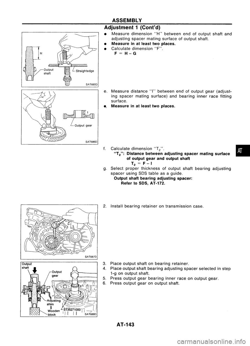
• Measure dimension "H"between endofoutput shaftand
adjusting spacermatingsurface ofoutput shaft.
• Measure inat least twoplaces.
• Calculate dimension "F".
F=H-G
e. Measure distance"I"between endofoutput gear(adjust-
ing spacer matingsurface) andbearing innerracefitting
surface .
• 0
Measure inat least twoplaces.
f. Calculate dimension "T
2". •
"T 2": Distance between adjusting spacermatingsurface
of output gearandoutput shaft
T
2
=
F- I
g. Select proper thickness ofoutput shaftbearing adjusting
spacer usingSOStable asaguide.
Output shaftbearing adjusting spacer:
Refer to50S, AT-172.
2. Install bearing retainer ontransmission case.
3. Place output shaftonbearing retainer.
4. Place output shaftbearing adjusting spacerselected instep
1-g onoutput shaft.
5. Press output gearbearing innerraceonoutput gear.
6. Press output gearonoutput shaft.
AT-143
Page 144 of 1701
SAT689DASSEMBLY
Adjustment 1(Cont'd)
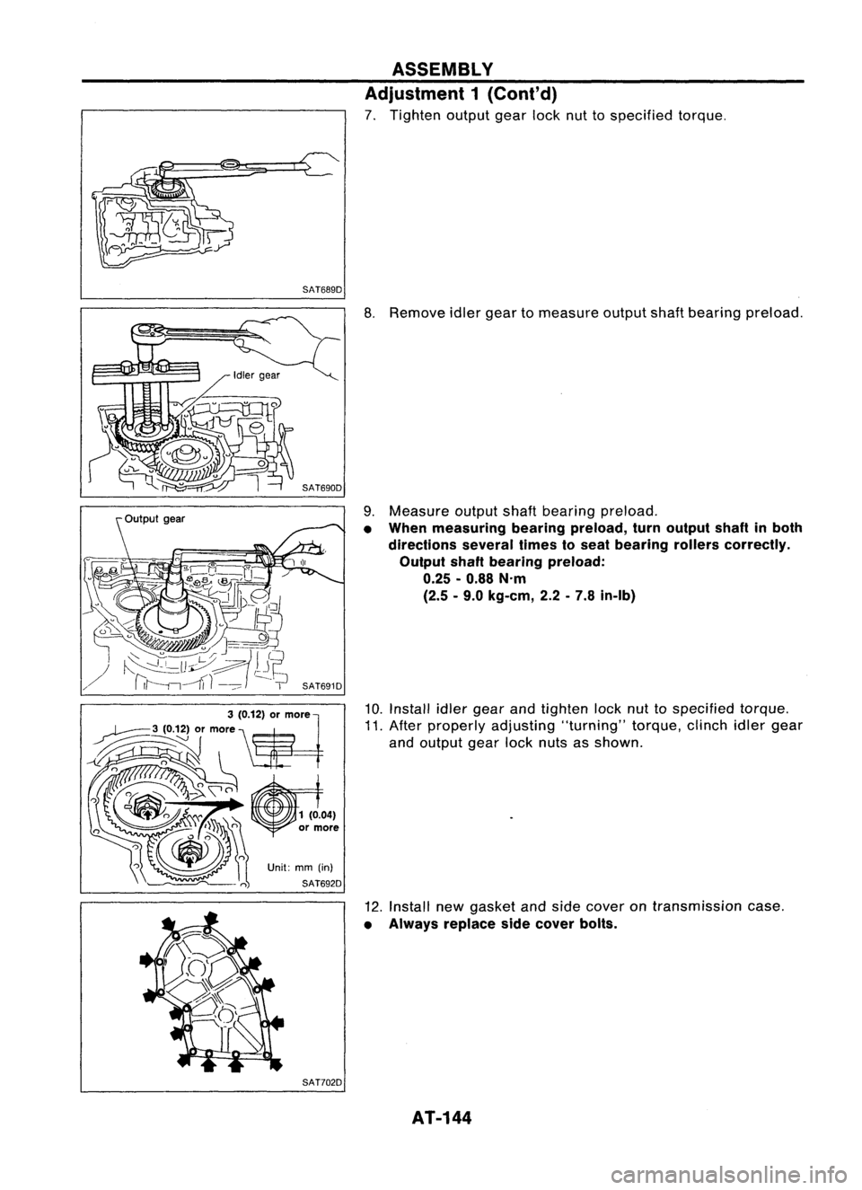
7. Tighten outputgearlocknuttospecified torque.
SAT702D
8.
Remove idlergear tomeasure outputshaftbearing preload.
9. Measure outputshaftbearing preload.
• When measuring bearingpreload, turnoutput shaftinboth
directions severaltimestoseat bearing rollerscorrectly.
Output shaftbearing preload:
0.25 -0.88 N'm
(2.5 -9.0 kg-em, 2.2-7.8 in-Ib)
10. Install idlergear andtighten locknuttospecified torque.
11. After properly adjusting "turning"torque,clinchidlergear
and output gearlocknuts asshown.
12. Install newgasket andside cover ontransmission case.
• Always replace sidecover bolts.
AT-144
Page 145 of 1701
SAT341D
SAT438D
SAT439D
KV31101300 NAT064 ASSEMBLY
Adjustment 1(Cont'd)
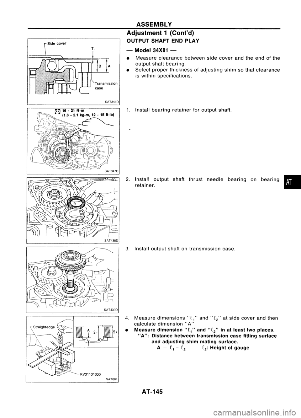
OUTPUT SHAFTENDPLAY
- Model 34X81-
• Measure clearance betweensidecover andtheend ofthe
output shaftbearing.
• Select proper thickness ofadjusting shimsothat clearance
is within specifications.
1. Install bearing retainer foroutput shaft.
2. Install output shaftthrust needle bearing onbearing •
retainer.
3. Install output shaftontransmission case.
4. Measure dimensions"
£1"
and"
£2"
atside cover andthen
calculate dimension "A".
• Measure dimension
"f/'
and
"f
2"
inat least twoplaces.
"A":
Distance betweentransmission casefitting surface
and adjusting shimmating surface.
A
= f
1-£2 £2:
Height ofgauge
AT-145
Page 146 of 1701
SAT440DASSEMBLY
Adjustment 1(Cont'd)
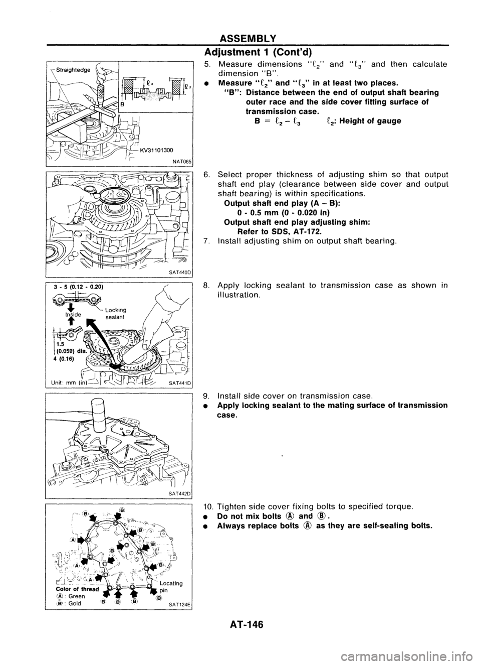
5. Measure dimensions
"f
2"
and
"f
3"
andthen calculate
dimension "8".
• Measure"
f
2"
and"
fa"
inat least twoplaces.
"B": Distance betweentheend ofoutput shaftbearing
outer raceandtheside cover fitting surface of
transmission case.
B
=
£2-
fa
f
2:
Height ofgauge
6. Select proper thickness ofadjusting shimsothat output
shaft endplay (clearance betweensidecover andoutput
shaft bearing) iswithin specifications.
Output shaftendplay (A-B):
o -
0.5
mm
(0-0.020
in)
Output shaftendplay adjusting shim:
Refer to50S,
AT-H2.
7. Install adjusting shimonoutput shaftbearing.
3 -5 (0.12 -0.20)
~
.... Locking
lide sealant
SAT441D
SAT442D
8.
Apply locking sealant totransmission caseasshown in
illustration.
9. Install sidecover ontransmission case.
• Apply locking sealant tothe mating surface oftransmission
case.
10. Tighten sidecover fixingboltstospecified torque.
• Donot mix bolts
@
and
CID.
• Always replace bolts
@
asthey areself-sealing bolts.
AT-146
Page 147 of 1701
Forwardclutch
assembly
Bearing race
m
@
ASSEMBLY
Assembly 2
- All models -
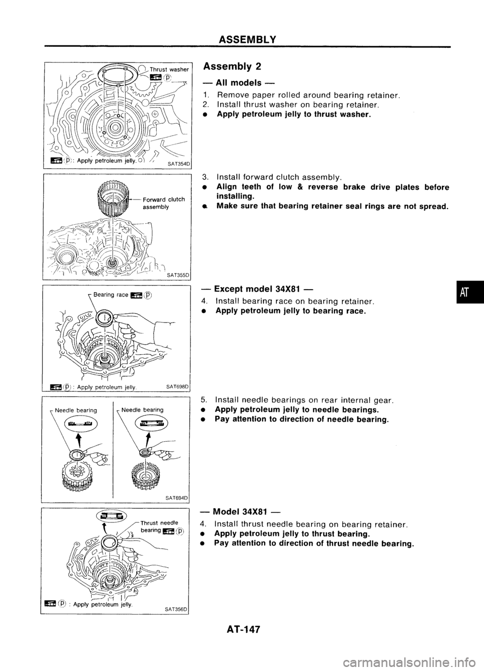
1. Remove paperrolledaround bearing retainer.
2. Install thrustwasher onbearing retainer.
• Apply petroleum jellytothrust washer.
3. Install forward clutchassembly.
• Align teethoflow
&
reverse brakedriveplates before
installing.
.. Make surethatbearing retainer sealrings arenotspread.
- Except model34X81-
4. Install bearing raceonbearing retainer.
• Apply petroleum jellytobearing race.
•
mep,:
Applypetroleum jelly.
SAT698D
Needle bearing
@
'-
(I
SAT694D
5.
Install needle bearings onrear internal gear.
• Apply petroleum jellytoneedle bearings.
• Pay attention todirection ofneedle bearing.
- Model 34X81-
4. Install thrustneedle bearing onbearing retainer.
• Apply petroleum jellytothrust bearing.
• Pay attention todirection ofthrust needle bearing.
AT-147
Page 148 of 1701
~ru,t
,,,dl,
beanng
m@
6
/)/11/
11
~I~u ,
"ill)
ASSEMBLY
Assembly 2(Cont'd)
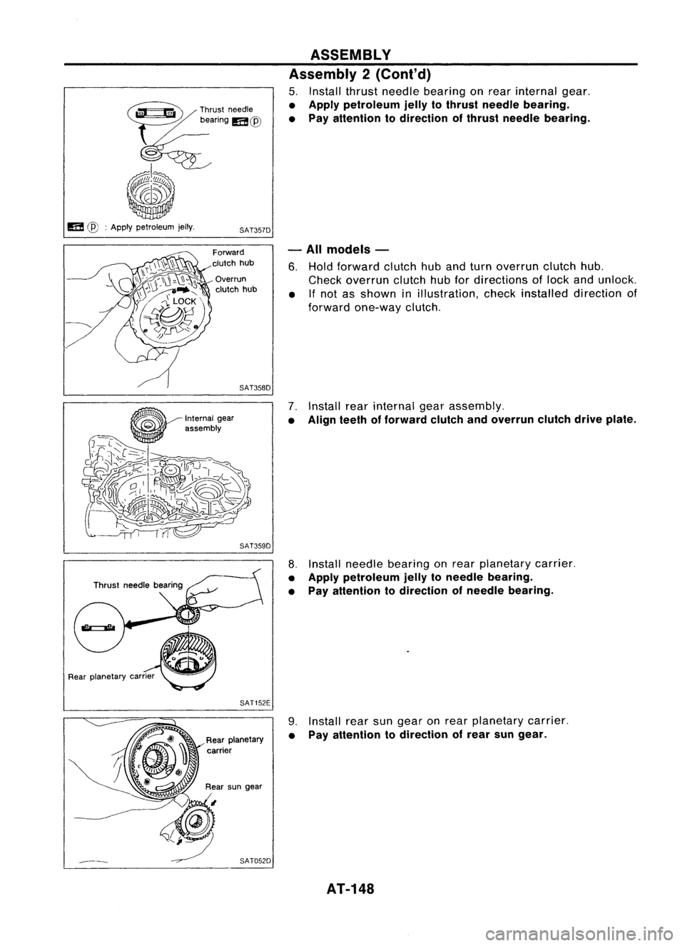
5. Install thrustneedle bearing onrear internal gear.
• Apply petroleum jellytothrust needle bearing.
• Pay attention todirection ofthrust needle bearing.
m
@:
Apply petroleum jelly.
SAT357D
Forward
clutch hub
Overrun
clutch hub
SAT358D
SAT359D -
All models -
6. Hold forward clutchhubandturn overrun clutchhub.
Check overrun clutchhubfordirections oflock andunlock.
• If
not asshown inillustration, checkinstalled direction of
forward one-way clutch.
"7.
Install rearinternal gearassembly.
• Align teethofforward clutchandoverrun clutchdriveplate.
,
~
"
u
Rear planetary carner
SAT152E
8.
Install needle bearing onrear planetary carrier.
• Apply petroleum jellytoneedle bearing.
• Pay attention todirection ofneedle bearing.
9. Install rearsungear onrear planetary carrier.
• Pay attention todirection ofrear sungear.
AT-148
Page 149 of 1701
Thrust
~.-b.. ~needle
~ bearing ASSEMBLY
Assembly 2(Cont'd)
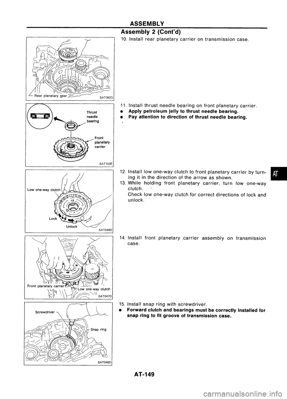
10. Install rearplanetary carrierontransmission case.
11. Install thrustneedle bearing onfront planetary carrier.
• Apply petroleum jellytothrust needle bearing.
• Pay attention todirection ofthrust needle bearing.
Front
planetary carrier
SAT153E
Screwdriver
12.
Install lowone-way clutchtofront planetary carrierbyturn- •
ing itin the direction ofthe arrow asshown.
13. While holding frontplanetary carrier,turnlowone-way
clutch.
Check lowone-way clutchforcorrect directions oflock and
unlock.
14. Install frontplanetary carrierassembly ontransmission
case.
15. Install snapringwith screwdriver.
• Forward clutchandbearings mustbecorrectly installedfor
snap ringtofit groove oftransmission case.
AT-149
Page 150 of 1701
Front
sun
gear
SAT154E
SAT156E ASSEMBLY
Assembly 2(Cont'd)
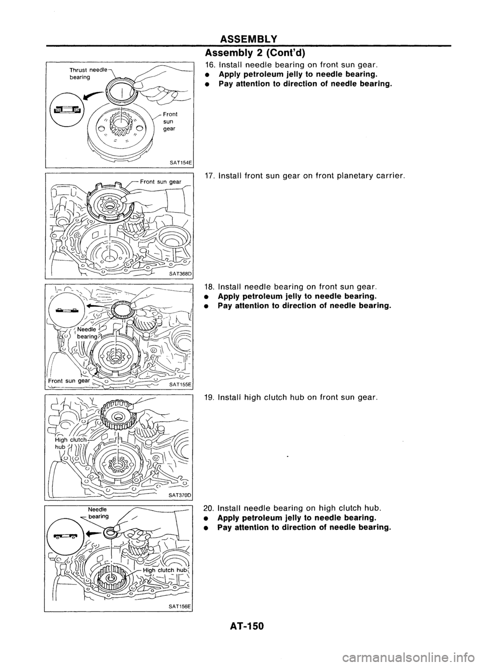
16. Install needle bearing onfront sungear.
• Apply petroleum jellytoneedle bearing.
• Pay attention todirection ofneedle bearing.
17. Install frontsungear onfront planetary carrier.
18. Install needle bearing onfront sungear.
• Apply petroleum jellytoneedle bearing.
• Pay attention todirection ofneedle bearing.
19. Install highclutch hubonfront sungear.
20. Install needle bearing onhigh clutch hub.
• Apply petroleum jellytoneedle bearing.
• Pay attention todirection ofneedle bearing.
AT-150