NISSAN ALMERA N15 1995 Service Manual
Manufacturer: NISSAN, Model Year: 1995, Model line: ALMERA N15, Model: NISSAN ALMERA N15 1995Pages: 1701, PDF Size: 82.27 MB
Page 181 of 1701
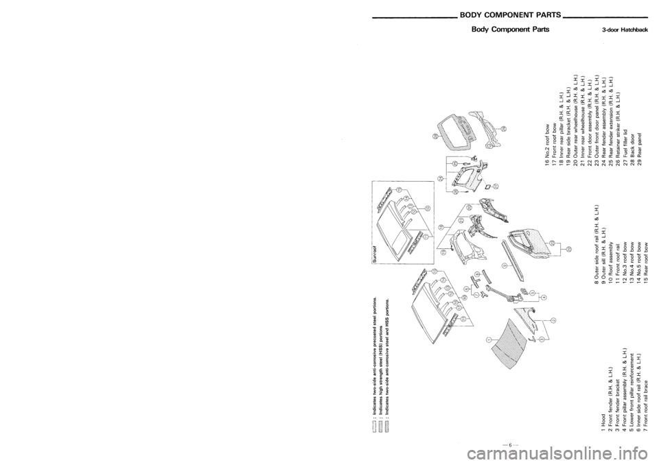
REPLACEMENTOPERATIONS
Outer Sill
3-doorhatchback Body
Component Parts 3-doorHatchback
Service Joint
:r:
cC--:-
-:r:
.co ~
I.-
c2S
~-
$
$
'+-
$
$
0
:r:
..0
.co
000
0
0
cC
E
lo-
..0 ..0
.c
..0
lo- '+-
CD CD
0
'+-
'+-
'+-
'+-
en
000
"'C
en
0
0000
l0-
o
.00 .00
co
lo-
lo-lo-
lo-
'+-
+-'
CV)
~
LO
lo-
lo- l0-
o
C
CD CD
0
00
0
co
+-' +-'
0
lo-
CD
::J ::J
0::
u.
Z
ZZ
cc
0 0
0
N
CV)
~
LO
00
(j)
~
\
@-~~~":::.~ ~
o .~ ~.~.~..
~-<0h~
,-
~:\~~
~
o
o
l-
t:
::J
en
.an.
(CNerlap cutting)
114
112A 112
:r:
-:r:
--
:r:
:i:i
~ ~
:i~
~~
--:-~ ~~
c2S
~
_
I
0
~ ~
:i~
:r:
:r:
:r:
0
:r:
:r:
cC
o:r:
~ ~
cC
:r:
0::
0
cC
~
-cC
-
0::
~
I
CD
CD
-
Q5
--c2S
cC en
en
c
>-
c
:r:
::J
::J
>-
:0
0
I
0
:0
co
0
00
cC
0
0..
E
cC
r/
+-'
..c
..c
E
c
-
CD
Q5
Q5
lo-
CD
CD
-
$ $
lo-
.:::£
CD CD
0
en
+-'
l0-
co
C,)
CD
en
0
en
><
0
..c
..c
en
co
CDCD
0
=
co
$
"'C
.:::£
..0 ..0
.0.
.0
$
co
lo-lo-
°C
;g
+-'
'+- l0-
O
C
CD
CD
+-'
l0-
a;
'+-
0
lo-
CD
co
lo-
"'C"'C
en
l0-
O
0
co
co
0
c
0 0
CD
-0
CD
CD
0
lo-
C
C
lo-
~
0
co
11 11
lo-
lo-
lo-
.00
lo-
lo-
"'C
'+-
CDCD CD
"'C
0-
+-'
Q;
lo-
lo-
+-'
lo-
'+-
'+-
C
"i=
111
N
c
lo-
CD
CD
C
CD
lo-
lo-
°co
Q5
~
I.-
0
0
c
co
+-'
c
0
+-'
co
co
+-'
C,)
co
CD
::J
::J
CD CD CD
co
CD
lo-
C C
lo-
::J
Z
u.
0::
0
u.
0
0::
0::0::
u.
0)
CC
c.o
I"'-
00
(j)
0
N
CV)
~
LO
c.o
I"'-
00
(j)
~ ~~
NN NN
NN N N
NN
Mol.
Gplug weld
M
IG Id/
(For 3panels plugweld method ).
p:;m
we
• r;=::::. •
A
:=::A:=: •
8~
.u.u.
G@ ~
111
Unit:mm
2-spot welds 3-spotwelds
-39-
-6-
Page 182 of 1701
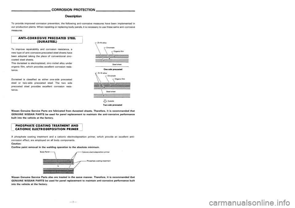
Description REPLACEMENT
OPERATIONS
Outer Sill
Sedan
5-door hatchback
FR
_4A
.cm
(OIerlap cutting)
_4
117
Unit:mm
119
112A 111A
114 111
114
M. I.G plug weld MIG seam weld/
(For 3panels plugweld method )P.an.
0int
;=::
· r .
A
=6=___
.8=:=
V
11
12
_4
111
112A
113
2-spot welds 3-spotwelds
Service
Joint
One-side precoated
Steel
sheet
~ Outside
Two-side precoated
Zn-Ni
alloy
Cationic electrodeposition primer
PHOSPHATE
COATINGTREATMENT AND
CATIONIC ELECTRODEPOSITION PRIMER
ANTI-CORROSIVE
PRECOATEDSTEEL
(DURASTEEL)
To
provide improved corrosion prevention, thefollowing anti-corrosive measureshavebeen implemented in
our production plants.Whenrepairing orreplacing bodypanels, itis necessary touse these sameanti-corrosive
measures.
Nissan Genuine ServicePartsalsoaretreated inthe same manner. Therefore, itis recommended tbat
GENUINE NISSANPARTSbeused forpanel replacement tomaintain anti-corrosive performancebuilt
into thevehicle atthe factory.
A
phosphate coatingtreatment andacationic electrodeposition primer,whichprovide anexcellent anti-
corrosion effect,areemployed onallbody components.
Caution:
Confine paintremoval inthe welding operation tothe absolute minimum.
Durasteel
isclassified aseither one-side precoated
steel ortwo-side precoated steel.Thetwo side
precoated steelprovides excellent corrosion resis-
tance. To
improve repairability andcorrosion resistance, a
new type ofanti-corrosive precoatedsteelsheets have
been adopted takingtheplace ofconventional zinc-
coated steelsheets.
This durasteel iselectroplated, zinc-nickelalloyunder
organic film,which provides excellent corrosion resis-
tance.
Nissan Genuine ServicePartsarefabricated fromdurasteel sheets.Therefore, itis recommended that
GENUINE NISSANPARTSbeused forpanel replacement tomaintain theanti-corrosive performance
built intothevehicle atthe factory.
-7-
-38-
Page 183 of 1701
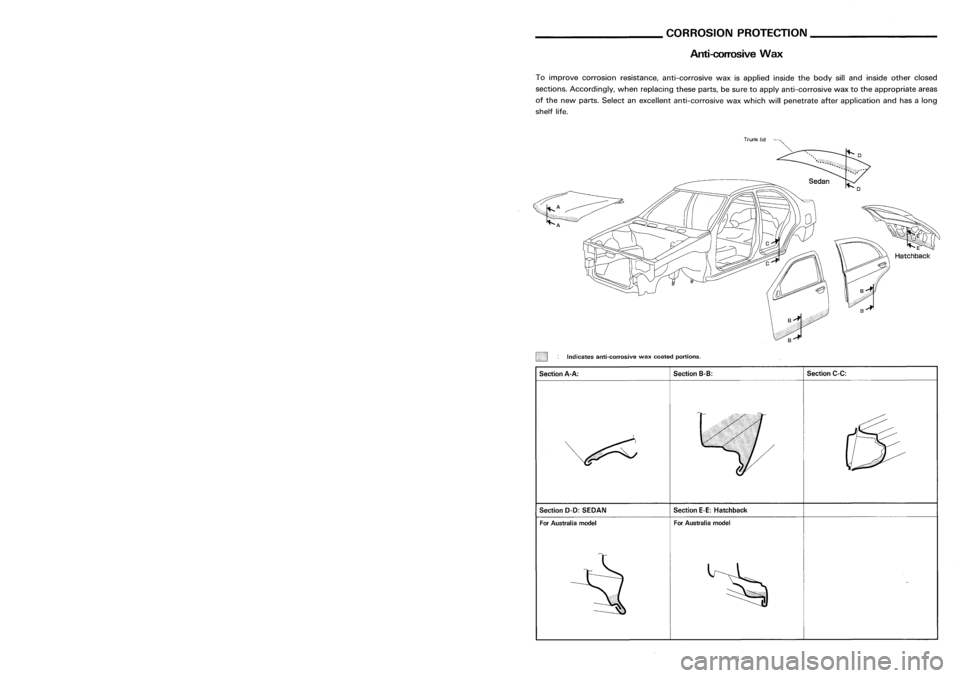
REPLACEMENTOPERATIONS
Center Pillar
Sedan
5-door hatchback
________
CORROSIONPROTECTION _
Anti-corrosive Wax
E
Hatchback
Section C-C:
For Australia model
Section
E-E:Hatchback
Section
8-8:
:
Indicates anti-corrosive waxcoated portions.
A
For Australia model
Section
0-0:SEDAN
Section
A-A:
To
improve corrosion resistance, anti-corrosive waxisapplied insidethebody silland inside otherclosed
sections. Accordingly, whenreplacing theseparts,besure toapply anti-corrosive waxtothe appropriate areas
of the new parts. Select anexcellent anti-corrosive waxwhich willpenetrate afterapplication andhasalong
shelf life.
FR
FR
117
111A
o
117
114
111A
Upper center pillarhinge brace
112
Lower center pillar
hinge brace
112
111
113
113
116 114
.cm.
( Overl apcutt ing)
Seat beltancher
reinforcement
Unit:mm
FR
Service
Joint
2-spot welds 3-spotwelds M.
I.
G plug weld MIG seam weld/
(For 3panels plugweld method )P:
F
weld
• rr= •
A
==-= •
B~
..LLLL
G1J --- ~
-37-
-8-
Page 184 of 1701
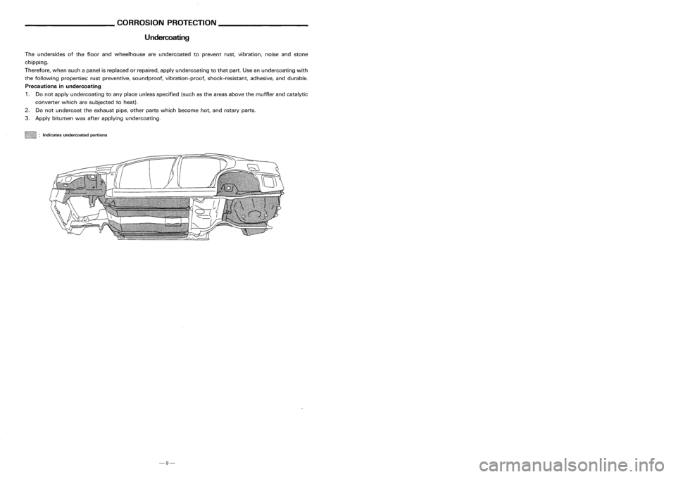
Undercoating REPLACEMENT
OPERATIONS
Front Pillar
(Work afterhoodledge reinforcement hasbeen removed.)
116
1lIl..
(Dri pchannel)
an
(Outer)
112
c;;;;?
FR
112
112
116
Unit:mm
<:=i
FR
1lIl..
( Inner)
112
~
113 :::::-----
Service
Joint
~I!!!!!!!!iiii!!!!!i!II :
Indicates undercoated portions
The
undersides ofthe floor andwheelhouse areundercoated toprevent rust,vibration, noiseandstone
chipping.
Therefore, whensuchapanel isreplaced orrepaired, applyundercoating tothat part. Useanundercoating with
the following properties: rustpreventive, soundproof, vibration-proof, shock-resistant, adhesive,anddurable.
Precautions inundercoating
1. Donot apply undercoating toany place unless specified (suchasthe areas above themuffler andcatalytic
converter whicharesubjected toheat).
2. Donot undercoat theexhaust pipe,other partswhich become hot,androtary parts.
3. Apply bitumen waxafter applying undercoating.
2-spotwelds 3-spotwelds
M.I.G plug wel(d For3panels plugweld method )..~:
G(F:~dm
weld/
• rr= •
A
==-=.
B~
.LLLL
GTJ --- ~
-9-
-36-
Page 185 of 1701
REPLACEMENTOPERATIONS
Front SideMember (PartialReplacement)
(Work afterradiator coresupport hasbeen removed.) ________
CORROSIONPROTECTION _
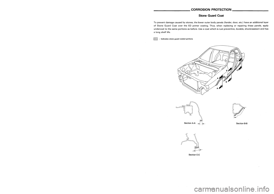
Stone Guard Coat
SectionB-B
Section
A-A
--r':":'
To
prevent damage causedbystones, thelower outerbodypanels (fender, door,etc.)have anadditional layer
of Stone Guard CoatovertheEDprimer coating. Thus,when replacing orrepairing thesepanels, apply
undercoat tothe same portions asbefore. Useacoat which isrust preventive, durable,shockresistant andhas
a long shelf life.
~mm1111i :
Indicates stoneguard coated portions
114
Patch
118
111
115
114
hoodledge
panel
117
111
Unit:mm
8
Patch
""
"
"
(Thickness: 1mm)
-\
Service
Joint
(This figure showrightfront sidemember)
2-spot welds 3-spotwelds M.1.
Gplug weld MIG seam weld/
(For 3panels plugweld method )P1ID.~irit
F
weld
• rr=
.A=-= .B~
G1J --- ~
Section
C-C
-35- -10-
Page 186 of 1701
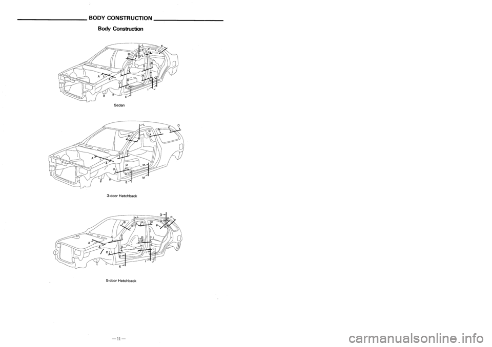
BODYCONSTRUCTION _
------------
BodyConsb"uction. REPLACEMENT
OPERATIONS _
------------
Hoodledge(PartialReplacement)
(Work afterradiator coresupport hasbeen removed.)
114AUnit:mm
Before
installing
hoodledge reinforcement.
117
Service
Joint
(This figure showrightsidehoodledge)
Sedan
3-d oar Hatchback
5-door Hatchback 2-spot
welds 3-spotwelds
M.1.
Gplug weld )
M.I.
Gseam weld/
(For 3panels plugweld method. Pointweld
· r
.A~ .B~
.an.F
-34-
-11-
Page 187 of 1701
REPLACEMENTOPERATIONS _
------------
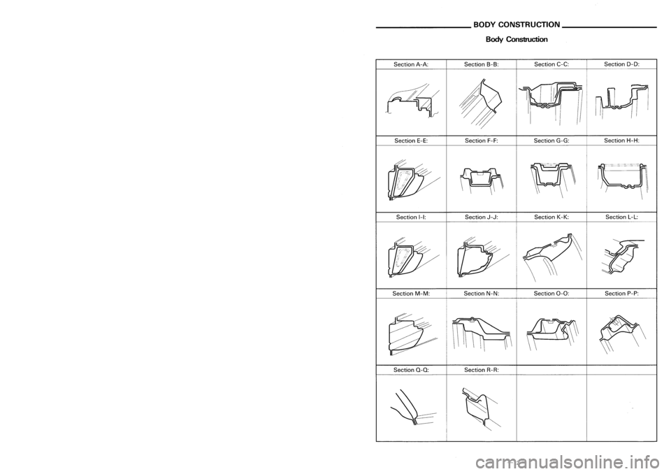
RadiatorCoreSupport (PartialReplacement) BODY
CONSTRUCTION _
-----------
BodyConstruction
\
Section
L-L:
Section P-P:
Section
D-D:
Section H-H:
Section K-K:
Section
C-C:
Section G-G:
Section 0-0:
Section
J-J:
Section
F-F:
Section
8-8:
. Section N-N:
Section
I-I:
Section
E-E:
Section
A-A:
Section M-M:
_1
FR
(
e
4orll3 *
indicates thatthere isan equivalent wel~ing.portion
with thesame dimensions onthe opposite Side.
o
*
e
3
or 112
FR
Service
Joint
Section
0-0:
Section
R-R:
2-spot welds 3-spotwelds
M.1.Gplug weld )M.I.Gseam weld/
(Point weld
For 3panels plugweld m.ethod
· r ·
A
=='*= •
B
===:=
.an
F
-33- -12-
Page 188 of 1701
Description
_________
BODYALIGNMENT _
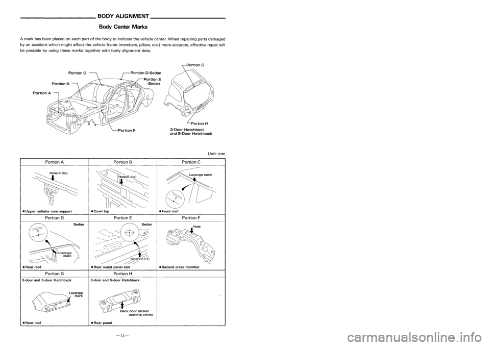
Body Center Marks ________
REPLACEMENTOPERATIONS _
SYMBOLS FORCUITING AND
WELDING/BRAZING OPERATIONS
..J
3-spot welds
(3-panel overlapping portions)
2-SDOt
welds
(2-panel overlapping portions)
••••
2-spot
welds
0000
3-spot
welds
Spot
weld
Brazing
Soldering
(ItIlI)
M.LG. seamweld/
Point weld
Saw
cutor
air chisel cut
•
•
•
M.LG. plugweld
-
The
indentification ofthe cutting andthewelding/brazing symbolsusedthroughout thisguide isgiven inthe
following pages
Portion F
Portion
C
Unit:
mm
Porton
H
3-Door Hatchback
and 5-Door Hatchback
• Front roof
• Second crossmember
Portion
D-Sedan
Portion E
-Sedan
Portion F
Portion E
Portion
8
Portion
G
~
Slot(7X 11)
/~/
• Rear waist panelslot
•
Cowl top
Portion
BPortion
C
Hole(4
dial
Portion
A
Portion D
Portion
A
• Rear roof
•
Upper radiator coresupport
A
mark hasbeen placed oneach partofthe body toindicate thevehicle center.Whenrepairing partsdamaged
by an accident whichmightaffectthevehicle frame(members, pillars,etc.)more accurate, effectiverepairwill
be possible byusing these marks together withbody alignment data.
Portion G
3-door and5-door Hatchback
Lozenge
mark
Portion
H
3-door and5-door Hatchback Sealing
• Rear roof •
Rear panel
-13- -32-
Page 189 of 1701
__________ PRECAUTIONS _
_ BODYALIGNMENT _
Precautions ForHandling HighStrength Steel
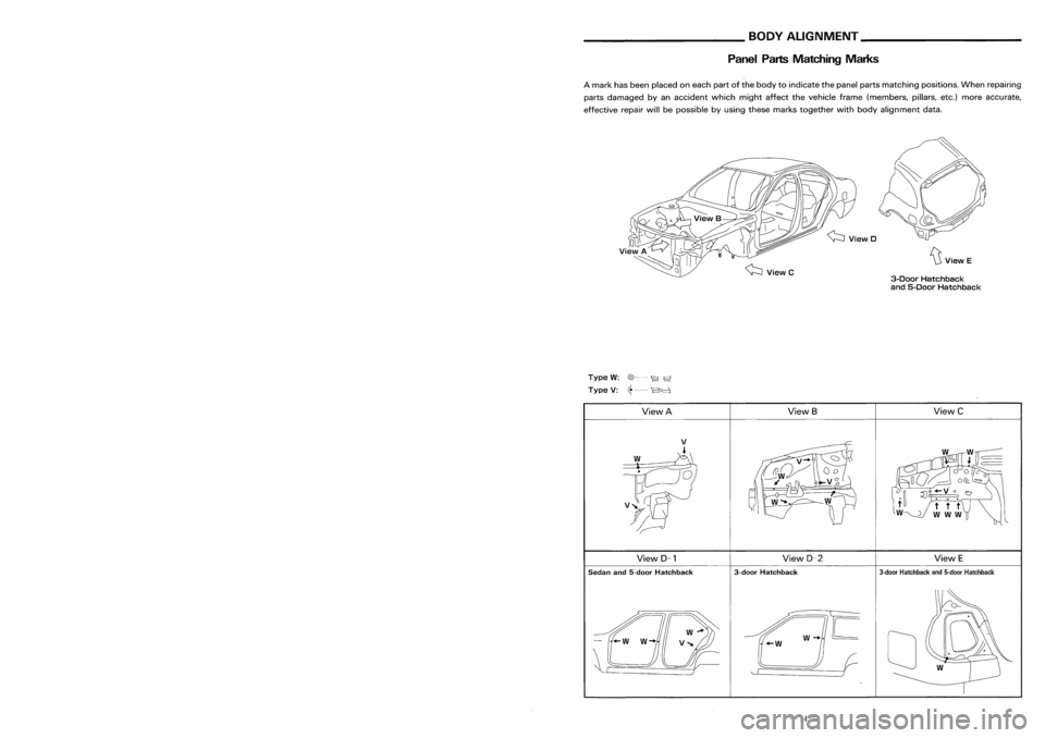
PanelPartsMatching Marks
~ViewE
3-Door Hatchback
and 5-Door Hatchback
A
mark hasbeen placed oneach partofthe body toindicate thepanel partsmatching positions.Whenrepairing
parts damaged byan accident whichmightaffectthevehicle frame(members, pillars,etc.)more accurate,
effective repairwillbepossible byusing these marks together wi~hbody alignment data.
Welding
current
Pressure
Unit:mrr
(C•
Thickness
(t)
Minimum pitch(
Q )
0.6 (0.024)
I
10 (0.39)
orover
0.8 (0.031) 12(0.47)
orover
1.0 (0.039) 18(0.71)
orover
1.2 (0.047) 20(0.79)
orover
1.6 (0.063) 27(1.06)
orover
~71) 31
11.221
orover
•
Follow established specifications forthe
appropriate pressurelevel,current leveland
weld time.
• Follow thespecifications forthe proper
welding pitch.
• After welding, weldingstrength mustbe
tested.
J
Type
W:
@----- ~
Et
Type V:~----- ~
View A ViewS
ViewC
View D-1 View
D-2
ViewE
Sedan and5-door Hatchback 3-door
Hatchback
3-door
Hatchback and5-door Hatchback
/w-..IE
+-W
II (-
'- r )
o
-31- -14-
Page 190 of 1701

__________ BODYALIGNMENT _
_ PRECAUTIONS _
Description PrecautionsForHandling HighStrength Steel
• Alldimensions indicatedinfigures areactual ones.
• When usingatracking gauge,adjustbothpointers toequal length. Thencheck thepointers andgauge
itself tomake surethere isno free play.
• When ameasuring tapeisused, check tobe sure there isno elongation, twistingorbending.
• Measurements shouldbetaken atthe center ofthe mounting holes.
• Anasterisk
(*)
following thevalue atthe measuring pointindicates thatthemeasuring pointonthe other
side issymmetrically thesame value.
• The coordinates ofthe measurement pointsarethe distances measured fromthestandard lineof"X", "V"
and "Z".
EngineCompartment
D=2T+3(mm)
D=2T+O.12 (in)
•
The electrode tipdiameter mustbereformed
properly according tothe panels thickness.
•
The spot ungget onHSS panel isharder than
that ofan ordinary steelpanel.
Therefore, forspot cutting HSSpanel, ahigh
torque drillofalow speed (1,000 to1,200
rpm) maybeused tomaintain itsdurability
and facilitate theoperation.
• HSS panels withatensile strength of785 to981 N/mm
2
(80to100 kg/mm
2,
114to142 klb/sq in),
used asreinforcement inthe door guard barand inthe bumper, istoo high intensile strength touse
for general repairs.Whenthesepanels aredamaged, theouter panels alsosustain consequential
damage; therefore, thesepanels arenever remedied withoutreplacing thedoor assembly orbumper
assembly.
2. Precautions inspot welding
This work should beperformed understandard workconditions. However,workcontrol mustbeexercised
as folloows:
SBF8?4GB
"Z":
Imaginary baseline
[200 mmbelow datum line
("OZ" atdesign plan)]
Front axlecenter
/
y (_)
(0)
Incorrect
Incorrect
Correct
D==Tip+diameter
T
,::=T====p=la::t_e=-=-_t_h=i_C=k=_n=_e_s=s= __,-- ~
• The panel surfaces mustbefitted toeach
other, leaving nogaps.
____
MEASURMENT _
SBT08?
-15- -30-