NISSAN ALMERA N15 1995 Service Manual
ALMERA N15 1995
NISSAN
NISSAN
https://www.carmanualsonline.info/img/5/57349/w960_57349-0.png
NISSAN ALMERA N15 1995 Service Manual
Trending: oil viscosity, EC-300, clutch, refrigerant type, AUX, oil filter, roof rack
Page 151 of 1701
Reverseclutch
assembly
SAT374DASSEMBLY
Assembly 2(Cont'd)
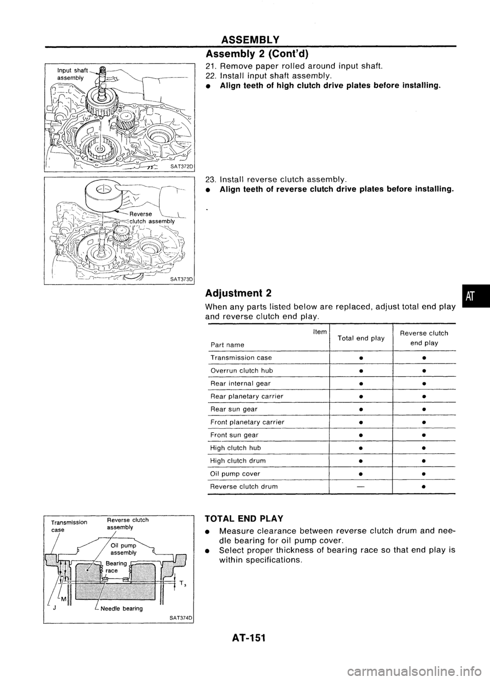
21. Remove paperrolledaround inputshaft.
22. Install inputshaft assembly.
• Align teethofhigh clutch driveplates before installing.
23. Install reverse clutchassembly.
• Align teethofreverse clutchdriveplates before installing.
Adjustment 2 •
When anyparts listed below arereplaced, adjusttotalendplay
and reverse clutchendplay.
Item Reverseclutch
Total endplay
endplay
Part name
Transmission case
•
•
Overrun clutchhub
••
Rear internal gear
••
Rear planetary carrier
•
•
Rear sungear
•
•
Front planetary carrier
•
•
Front sungear
•
•
High clutch hub
••
High clutch drum
••
Oil pump cover
••
Reverse clutchdrum
-
•
TOTAL ENDPLAY
• Measure clearance betweenreverseclutchdrumandnee-
dle bearing foroilpump cover.
• Select proper thickness ofbearing racesothat endplay is
within specifications.
AT-151
Page 152 of 1701
Transmissioncase SAT375DASSEMBLY
Adjustment 2(Cont'd)
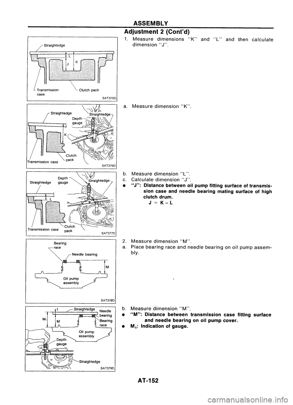
1. Measure dimensions "K"and"L"and then calculate
dimension
"J".
Transmission case
Depth
gauge
/Needle bearing SAT376D
SAT377D
a.
Measure dimension "K".
b. Measure dimension "L",
c. Calculate dimension
"J".
• "J":
Distance betweenoilpump fitting surface oftransmis-
sion case andneedle bearing matingsurface ofhigh
clutch drum.
J=K-L
2. Measure dimension "M".
a. Place bearing raceandneedle bearing onoil pump assem-
bly.
SAT378D
Straightedge
Straightedge SAT379D
b.
Measure dimension "M".
• "M":
Distance betweentransmission casefitting surface
and needle bearing onoilpump cover.
• M
1:
Indication ofgauge.
AT-152
Page 153 of 1701
ASSEMBLY
Adjustment 2(Cont'd)
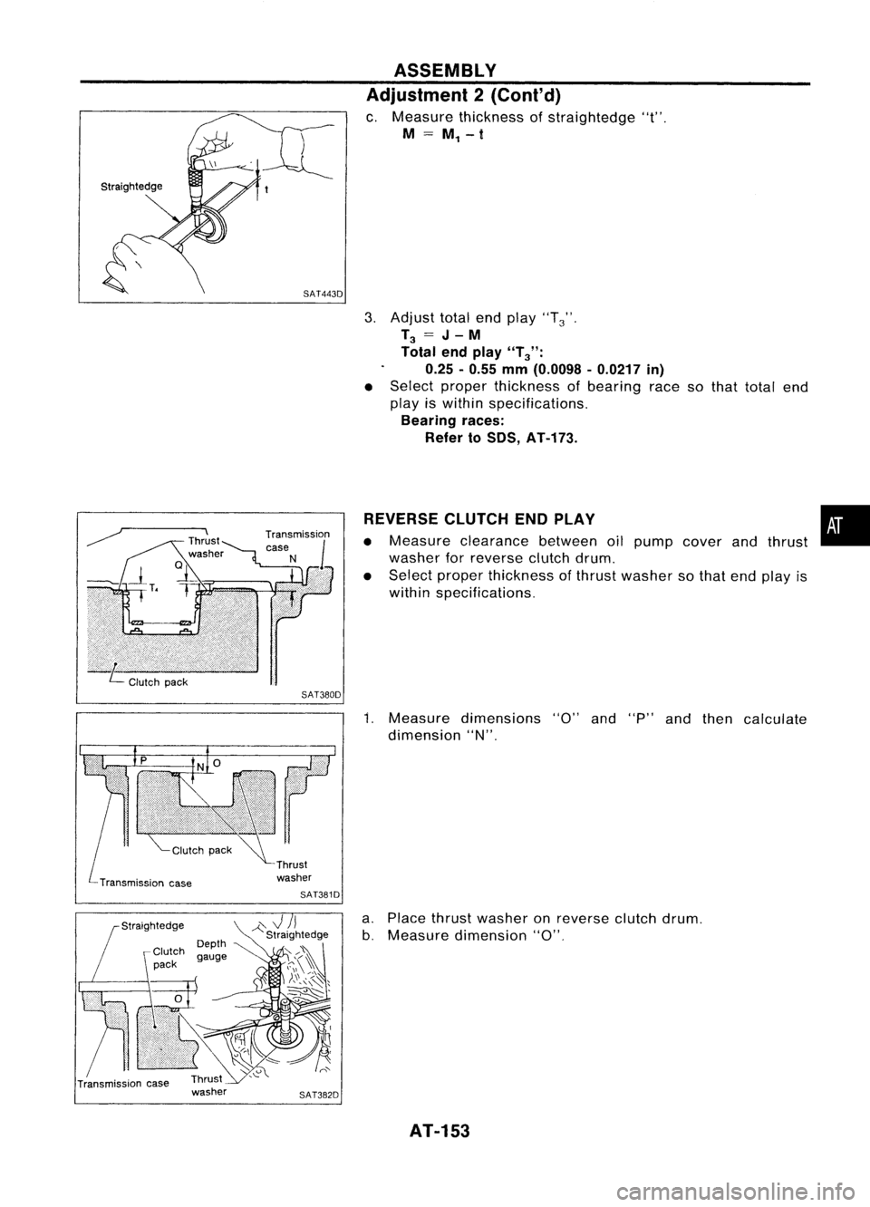
c. Measure thickness ofstraightedge "t".
M
=
M
1 -
t
3. Adjust totalendplay "T
3'"
T
3
=
J-
M
Total endplay
"T
3":
0.25 -0.55 mm(0.0098 -0.0217 in)
• Select proper thickness ofbearing racesothat total end
play iswithin specifications.
Bearing races:
Refer toSOS, AT-173.
Transmission case SAT380D
SAT381D REVERSE
CLUTCHENDPLAY
• Measure clearance betweenoilpump cover andthrust
washer forreverse clutchdrum.
• Select proper thickness ofthrust washer sothat endplay is
within specifications.
1. Measure dimensions "0"and"P"andthen calculate
dimension "N".
•
a. Place thrust washer onreverse clutchdrum.
b. Measure dimension "0".
AT-153
Page 154 of 1701
-Straightedge
Depth
gauge ASSEMBLY
Adjustment 2(Cont'd)
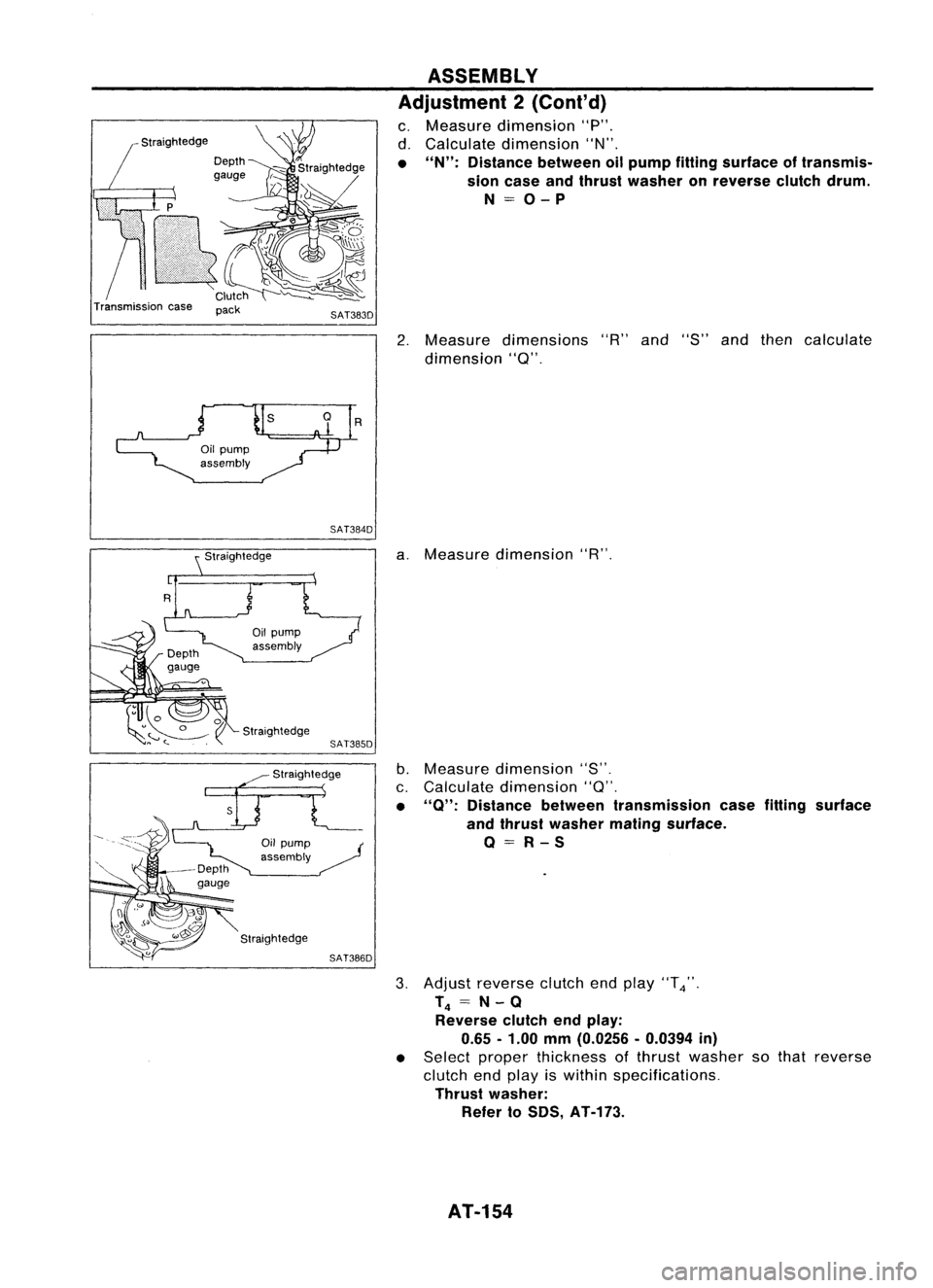
c. Measure dimension "P".
d. Calculate dimension "N".
• "N": Distance betweenoilpump fittingsurface oftransmis-
sion case andthrust washer onreverse clutchdrum.
N=O-P
Transmission case
pack
SAT383D
2.Measure dimensions "R"and "S"andthen calculate
dimension
"Q".
R
SAT384D
Straightedge
a.
Measure dimension "R".
b. Measure dimension "S".
c. Calculate dimension
"Q".
• "0": Distance betweentransmission casefitting surface
and thrust washer matingsurface.
O=R-S
3. Adjust reverse clutchendplay "T
4".
T
4
=
N-0
Reverse clutchendplay:
0.65 -1.00
mm
(0.0256 -0.0394
in)
• Select proper thickness ofthrust washer sothat reverse
clutch endplay iswithin specifications.
Thrust washer:
Refer toSDS, AT-173.
AT-154
Page 155 of 1701
Bearingrace
Thrustwasher SAT158E ASSEMBLY
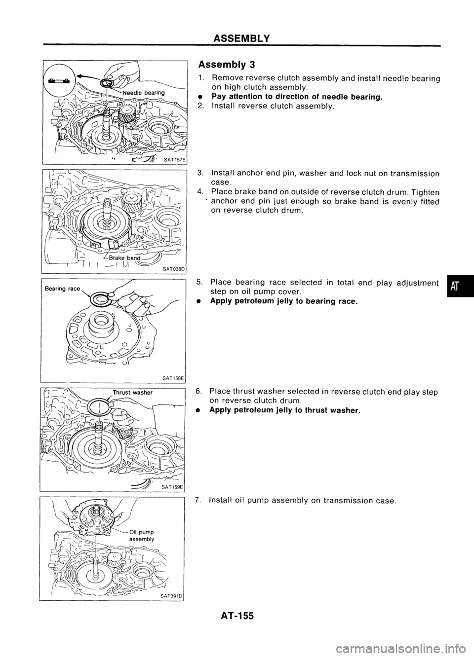
Assembly 3
1. Remove reverseclutchassembly andinstall needle bearing
on high clutch assembly.
• Pay attention todirection ofneedle bearing.
2. Install reverse clutchassembly.
3. Install anchor endpin,washer andlock nutontransmission
case.
4. Place brake bandonoutside ofreverse clutchdrum.Tighten
. anchor endpinjust enough sobrake bandisevenly fitted
on reverse clutchdrum.
5. Place bearing raceselected intotal endplay adjustment •
step onoil pump cover.
• Apply petroleum jellytobearing race.
6. Place thrust washer selected inreverse clutchendplay step
on reverse clutchdrum.
• Apply petroleum jellytothrust washer.
7. Install oilpump assembly ontransmission case.
AT-155
Page 156 of 1701
ASSEMBLY
Assembly 3(Cont'd)
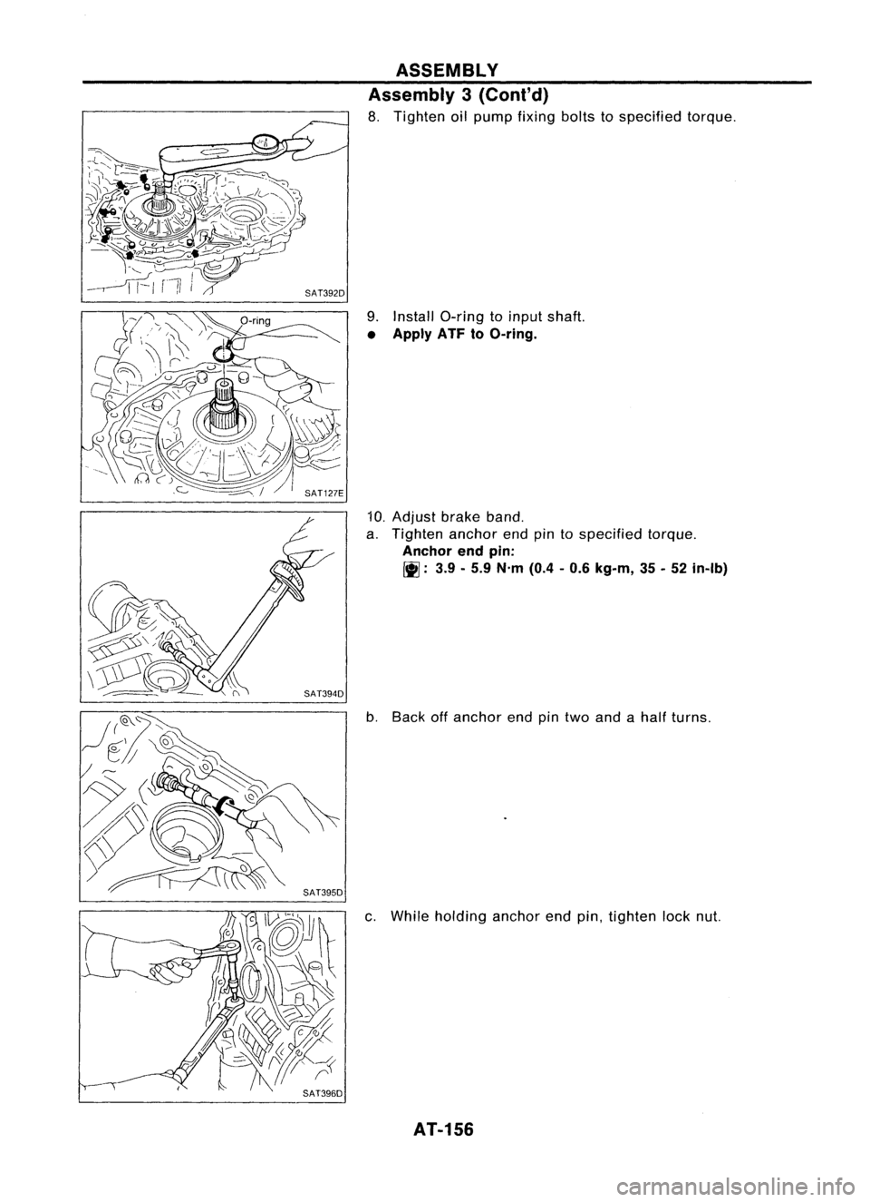
8. Tighten oilpump fixing boltstospecified torque.
9. Install O-ring toinput shaft.
• Apply ATFtoO-ring.
10. Adjust brakeband.
a. Tighten anchorendpintospecified torque.
Anchor endpin:
Ill:
3.9-5.9 N.m (0.4-0.6 kg-m, 35-52 in-Ib)
b. Back offanchor endpintwo and ahalf turns.
c. While holding anchorendpin,tighten locknut.
AT-156
Page 157 of 1701
SAT397D
Straightedge SAT695D
SAT696D ASSEMBLY
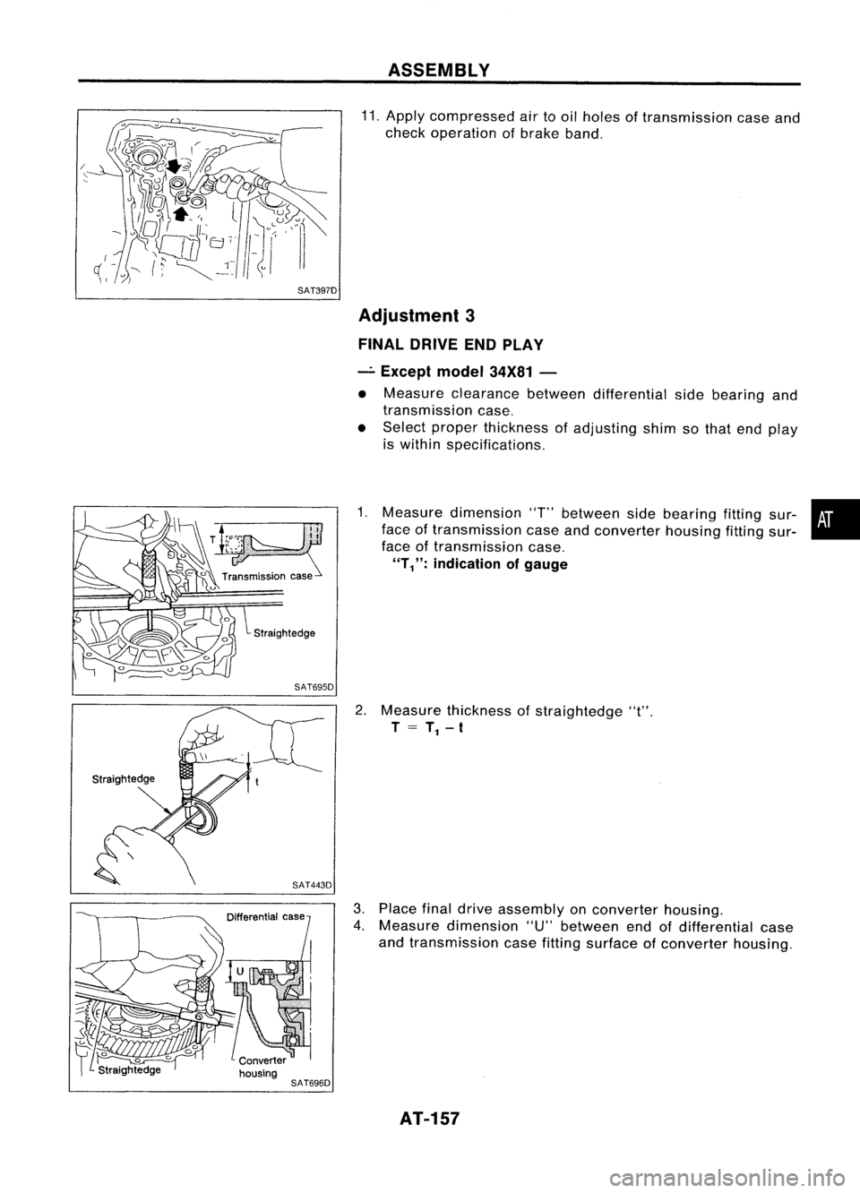
11. Apply compressed airtooil holes oftransmission caseand
check operation ofbrake band.
Adjustment 3
FINAL DRIVE ENDPLAY
_. Except model34X81-
• Measure clearance betweendifferential sidebearing and
transmission case.
• Select proper thickness ofadjusting shimsothat end play
is within specifications.
1. Measure dimension 'T"between sidebearing fittingsur-•
face oftransmission caseandconverter housingfittingsur-
face oftransmission case.
"T/':
indication ofgauge
2. Measure thickness ofstraightedge "t".
T
= T
1 -
t
3. Place finaldrive assembly onconverter housing.
4. Measure dimension "U"between endofdifferential case
and transmission casefitting surface ofconverter housing.
AT-157
Page 158 of 1701
ASSEMBLY
Adjustment 3
(Co nt'd)
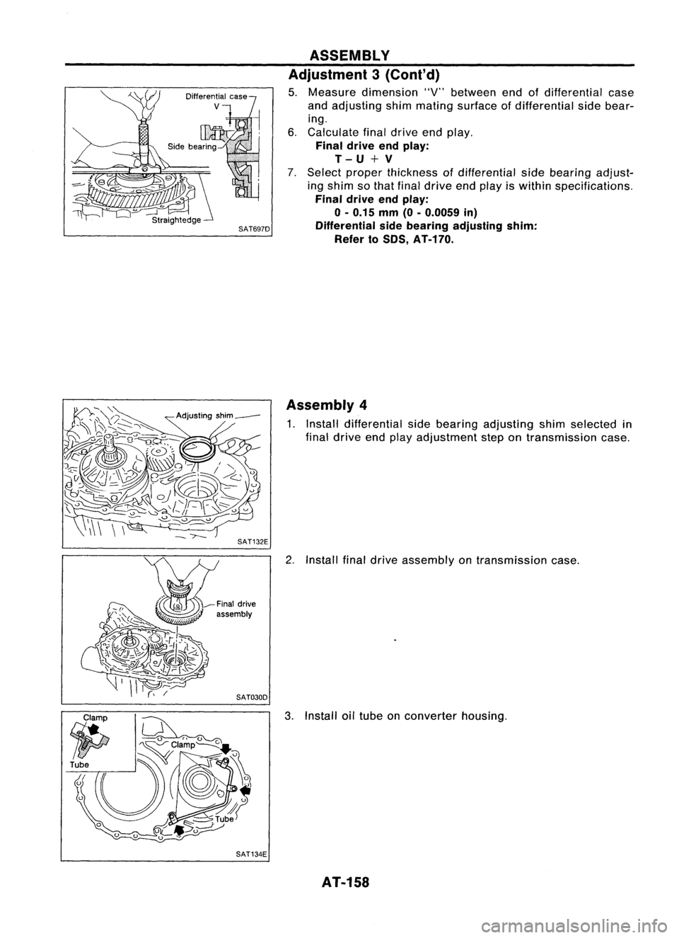
5. Measure dimension "V"between endofdifferential case
and adjusting shimmating surface ofdifferential sidebear-
ing.
6. Calculate finaldrive endplay.
Final drive endplay:
T-U+V
7. Select proper thickness ofdifferential sidebearing adjust-
ing shim sothat final drive endplay iswithin specifications.
Final drive endplay:
0-
0.15
mm
(0-0.0059
in)
SAT697D Differentialsidebearing adjusting shim:
Refer to80S, AT-170.
Assembly 4
1. Install differential sidebearing adjusting shimselected in
final drive endplay adjustment stepontransmission case.
2. Install finaldrive assembly ontransmission case.
3. Install oiltube onconverter housing.
SAT134E AT-158
Page 159 of 1701
3-5 (0.12 •0.20)
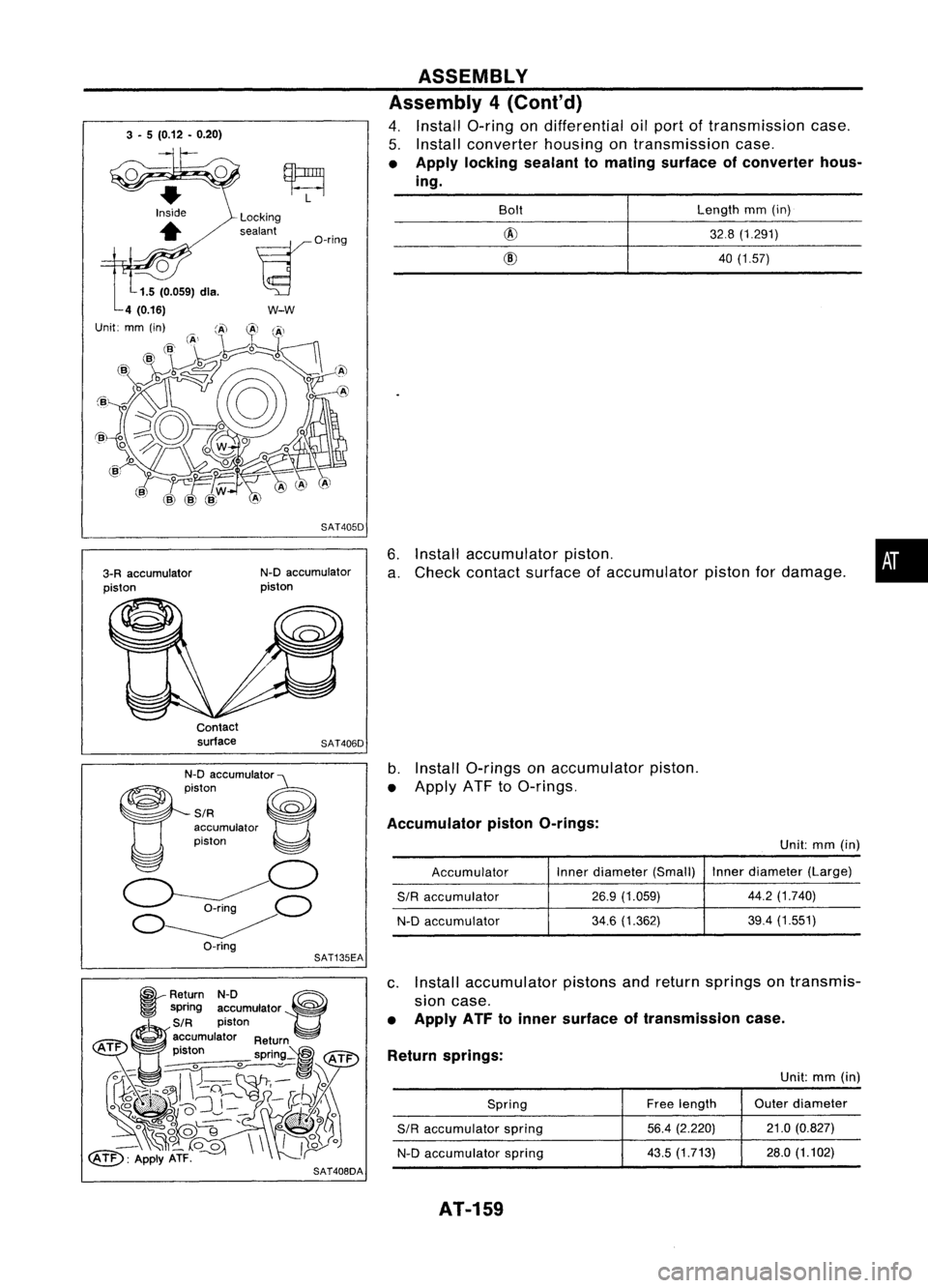
6.Install accumulator piston.
a. Check contact surface ofaccumulator pistonfordamage.
ASSEMBLY
Assembly 4(Cont'd)
4. Install a-ring ondifferential oilport oftransmission case.
5. Install converter housingontransmission case.
• Apply locking sealant tomating surface ofconverter hous-
ing.
•
Length
mm(in)
32.8 (1.291)
40 (1.57)
@
@
Bolt
SAT405D
w-w
N-D accumulator
piston
Locking
sealant
~O'i"9
3-R accumulator
piston
Unit:
Contactsurface
SAT406D
N-D accumUlato'e
~iston ~
SIR ~
accumulator
piston
o
~C)
O~
O-ring
b.
Install a-rings onaccumulator piston.
• Apply ATFtoa-rings.
Accumulator pistonO-rings:
Unit:mm(in)
Accumulator Inner
diameter (Small) Inner
diameter (Large)
SIR
accumulator
26.9
(1.059) 44.2
(1.740)
N-D accumulator
34.6
(1.362) 39.4
(1.551)
SAT135EA
~ Return N-D ~
~ spring accumulator ~
~S/R piston
@)
accumulator Return
ATF .
t
pIS on spring~
tATi="
~~ ~~'\\~
~~U~~~-1C .....~.~ ..
}~y)~:
° ~~~'
o*lf
_~o_
00\\
II~o
~: ApplyATF.
r
c.
Install accumulator pistonsandreturn springs ontransmis-
sion case.
• Apply ATFtoinner surface oftransmission case.
Return springs:
Unit:mm(in)
Spring Free
length Outer
diameter
SIR
accumulator spring
56.4
(2.220) 21.0
(0.827)
N-D accumulator spring
43.5
(1.713) 28.0(1.102)
SAT408DA
AT-159
Page 160 of 1701
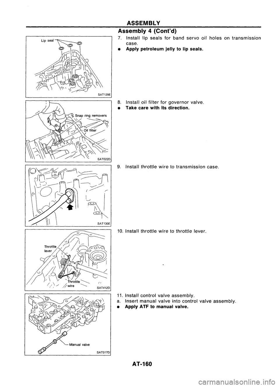
Installthrottle .
wIre totransm'
.
ISSlon case.
10.
Install th
rattle wiretothrattle lever.
11. I
nstall control
a. Insert manu valveassembl
• Apply ATF
t:I~:~v:alinto conir~1valve
valve.
assembly.
holes
ontransmiss'
Ion
ASSEMBLY
Assembly 4(C
7. Install ,.
ont'd)
case
tp
seals forband
• A . servooil
pply petroleum jellyto lip seals.
8. Install oilfilt
• Take carew~~
f.otr9?VernOr valve
I
s
dIrection. .
AT.160
Trending: load capacity, airbag, low beam, engine overheat, USB, flat tire, automatic transmission
