NISSAN NAVARA 2005 Repair Workshop Manual
Manufacturer: NISSAN, Model Year: 2005, Model line: NAVARA, Model: NISSAN NAVARA 2005Pages: 3171, PDF Size: 49.59 MB
Page 231 of 3171
ON-VEHICLE SERVICE
AT-223
D
E
F
G
H
I
J
K
L
MA
B
AT
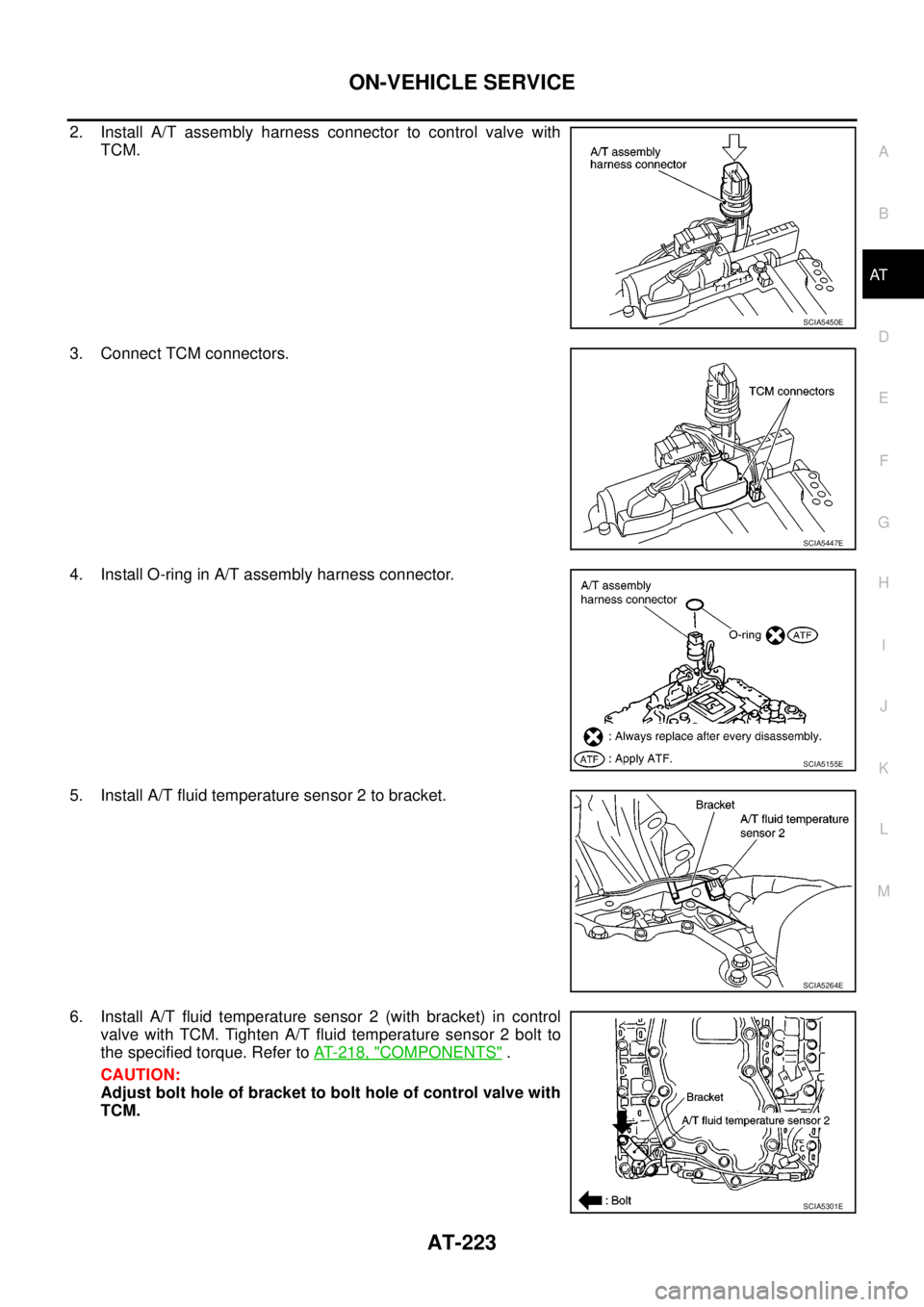
2. Install A/T assembly harness connector to control valve with
TCM.
3. Connect TCM connectors.
4. Install O-ring in A/T assembly harness connector.
5. Install A/T fluid temperature sensor 2 to bracket.
6. Install A/T fluid temperature sensor 2 (with bracket) in control
valve with TCM. Tighten A/T fluid temperature sensor 2 bolt to
the specified torque. Refer toAT- 2 1 8 , "
COMPONENTS".
CAUTION:
Adjust bolt hole of bracket to bolt hole of control valve with
TCM.
SCIA5450E
SCIA5447E
SCIA5155E
SCIA5264E
SCIA5301E
Page 232 of 3171
AT-224
ON-VEHICLE SERVICE
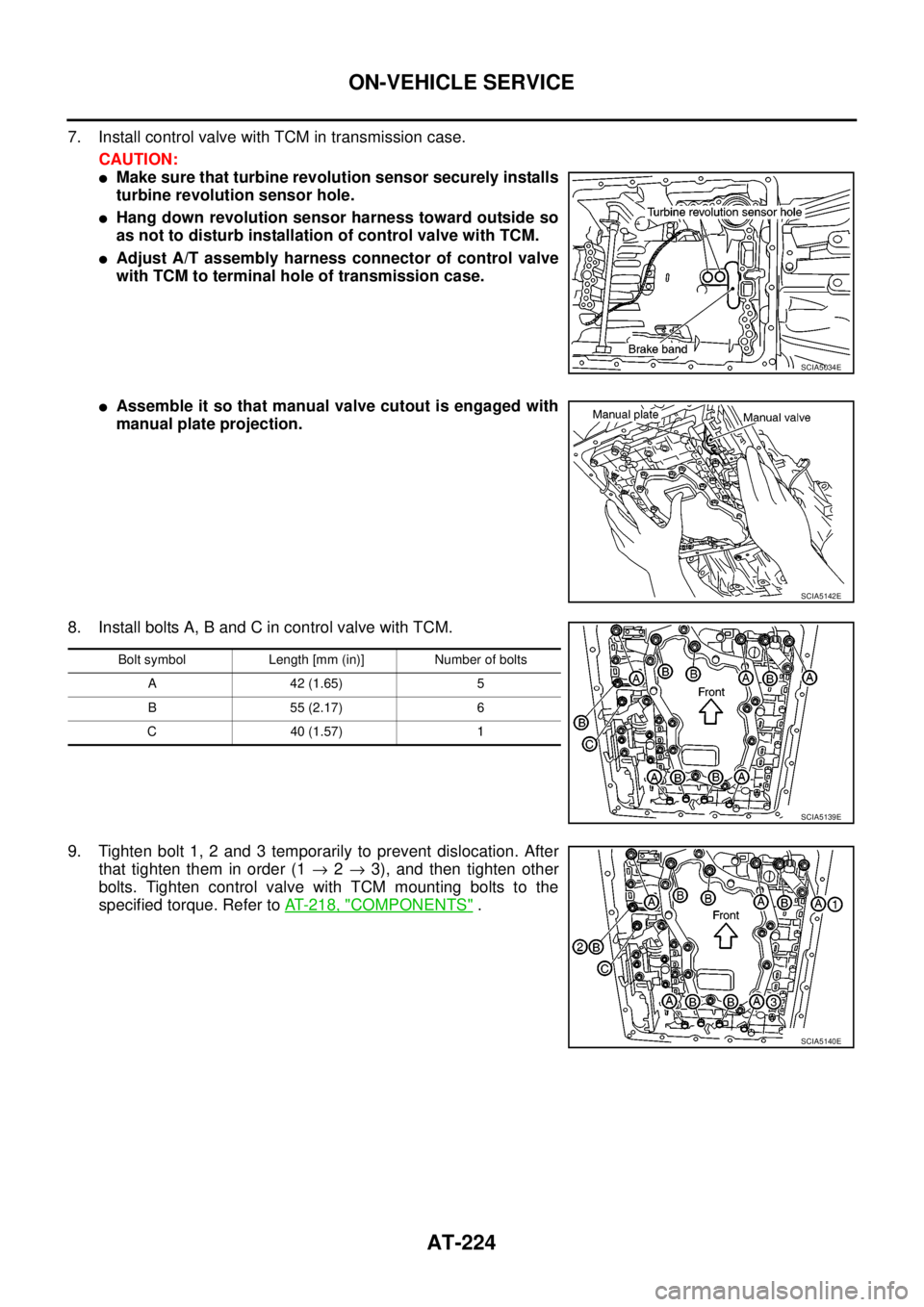
7. Install control valve with TCM in transmission case.
CAUTION:
lMake sure that turbine revolution sensor securely installs
turbine revolution sensor hole.
lHang down revolution sensor harness toward outside so
as not to disturb installation of control valve with TCM.
lAdjust A/T assembly harness connector of control valve
with TCM to terminal hole of transmission case.
lAssemble it so that manual valve cutout is engaged with
manual plate projection.
8. Install bolts A, B and C in control valve with TCM.
9. Tighten bolt 1, 2 and 3 temporarily to prevent dislocation. After
that tighten them in order (1®2®3), and then tighten other
bolts. Tighten control valve with TCM mounting bolts to the
specified torque. Refer toAT- 2 1 8 , "
COMPONENTS".
SCIA5034E
SCIA5142E
Bolt symbol Length [mm (in)] Number of bolts
A 42 (1.65) 5
B 55 (2.17) 6
C 40 (1.57) 1
SCIA5139E
SCIA5140E
Page 233 of 3171
ON-VEHICLE SERVICE
AT-225
D
E
F
G
H
I
J
K
L
MA
B
AT
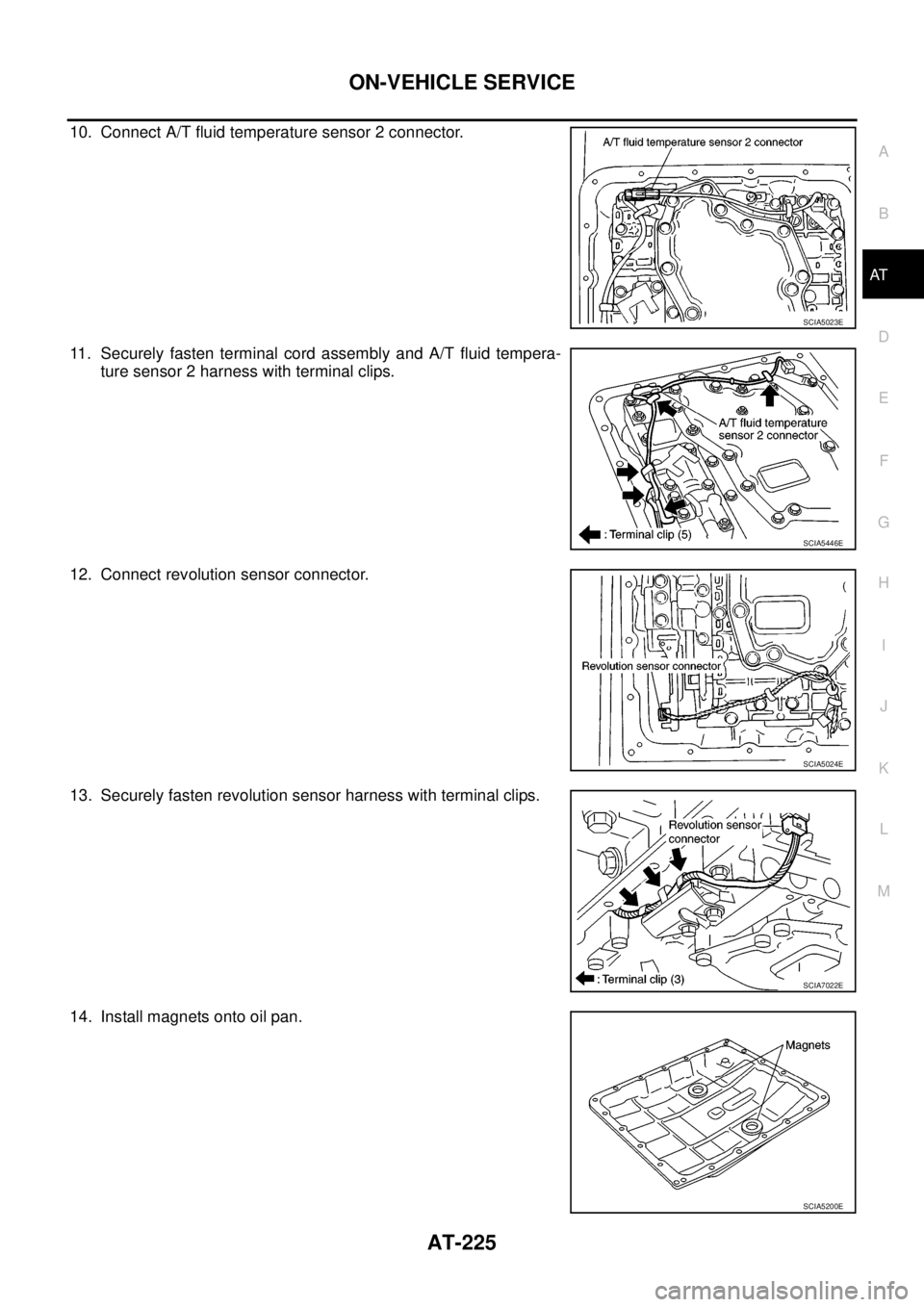
10. Connect A/T fluid temperature sensor 2 connector.
11. Securely fasten terminal cord assembly and A/T fluid tempera-
ture sensor 2 harness with terminal clips.
12. Connect revolution sensor connector.
13. Securely fasten revolution sensor harness with terminal clips.
14. Install magnets onto oil pan.
SCIA5023E
SCIA5446E
SCIA5024E
SCIA7022E
SCIA5200E
Page 234 of 3171
AT-226
ON-VEHICLE SERVICE
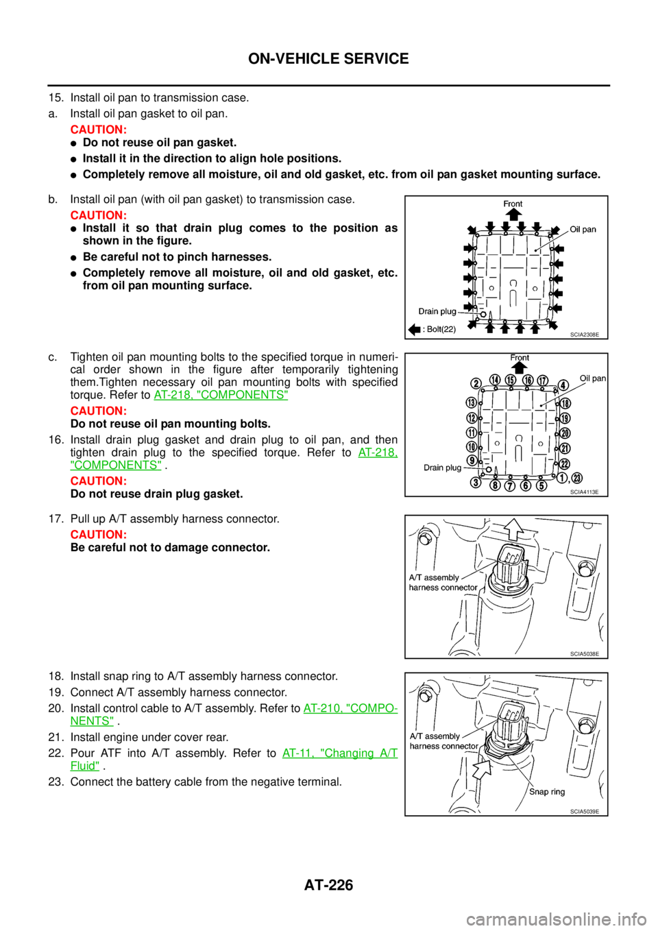
15. Install oil pan to transmission case.
a. Install oil pan gasket to oil pan.
CAUTION:
lDo not reuse oil pan gasket.
lInstall it in the direction to align hole positions.
lCompletely remove all moisture, oil and old gasket, etc. from oil pan gasket mounting surface.
b. Install oil pan (with oil pan gasket) to transmission case.
CAUTION:
lInstall it so that drain plug comes to the position as
shown in the figure.
lBe careful not to pinch harnesses.
lCompletely remove all moisture, oil and old gasket, etc.
from oil pan mounting surface.
c. Tighten oil pan mounting bolts to the specified torque in numeri-
cal order shown in the figure after temporarily tightening
them.Tighten necessary oil pan mounting bolts with specified
torque. Refer toAT- 2 1 8 , "
COMPONENTS"
CAUTION:
Do not reuse oil pan mounting bolts.
16. Install drain plug gasket and drain plug to oil pan, and then
tighten drain plug to the specified torque. Refer toAT-218,
"COMPONENTS".
CAUTION:
Do not reuse drain plug gasket.
17. Pull up A/T assembly harness connector.
CAUTION:
Be careful not to damage connector.
18. Install snap ring to A/T assembly harness connector.
19. Connect A/T assembly harness connector.
20. Install control cable to A/T assembly. Refer toAT- 2 1 0 , "
COMPO-
NENTS".
21. Install engine under cover rear.
22. Pour ATF into A/T assembly. Refer toAT-11, "
Changing A/T
Fluid".
23. Connect the battery cable from the negative terminal.
SCIA2308E
SCIA4113E
SCIA5038E
SCIA5039E
Page 235 of 3171
ON-VEHICLE SERVICE
AT-227
D
E
F
G
H
I
J
K
L
MA
B
AT
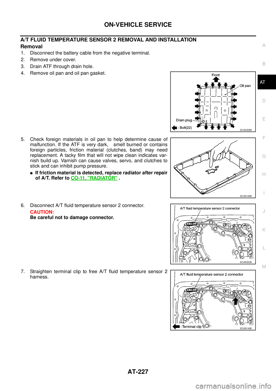
A/T FLUID TEMPERATURE SENSOR 2 REMOVAL AND INSTALLATION
Removal
1. Disconnect the battery cable from the negative terminal.
2. Remove under cover.
3. Drain ATF through drain hole.
4. Remove oil pan and oil pan gasket.
5. Check foreign materials in oil pan to help determine cause of
malfunction. If the ATF is very dark, smell burned or contains
foreign particles, friction material (clutches, band) may need
replacement. A tacky film that will not wipe clean indicates var-
nish build up. Varnish can cause valves, servo, and clutches to
stick and can inhibit pump pressure.
lIf friction material is detected, replace radiator after repair
of A/T. Refer toCO-11, "
RADIATOR".
6. Disconnect A/T fluid temperature sensor 2 connector.
CAUTION:
Be careful not to damage connector.
7. Straighten terminal clip to free A/T fluid temperature sensor 2
harness.
SCIA2308E
SCIA5199E
SCIA5023E
SCIA5146E
Page 236 of 3171
AT-228
ON-VEHICLE SERVICE
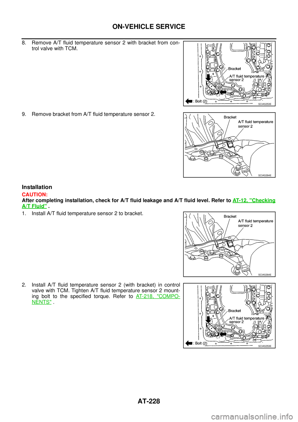
8. Remove A/T fluid temperature sensor 2 with bracket from con-
trol valve with TCM.
9. Remove bracket from A/T fluid temperature sensor 2.
Installation
CAUTION:
After completing installation, check for A/T fluid leakage and A/T fluid level. Refer toAT-12, "
Checking
A/T Fluid".
1. Install A/T fluid temperature sensor 2 to bracket.
2. Install A/T fluid temperature sensor 2 (with bracket) in control
valve with TCM. Tighten A/T fluid temperature sensor 2 mount-
ing bolt to the specified torque. Refer toAT- 2 1 8 , "
COMPO-
NENTS".
SCIA5253E
SCIA5264E
SCIA5264E
SCIA5253E
Page 237 of 3171
ON-VEHICLE SERVICE
AT-229
D
E
F
G
H
I
J
K
L
MA
B
AT
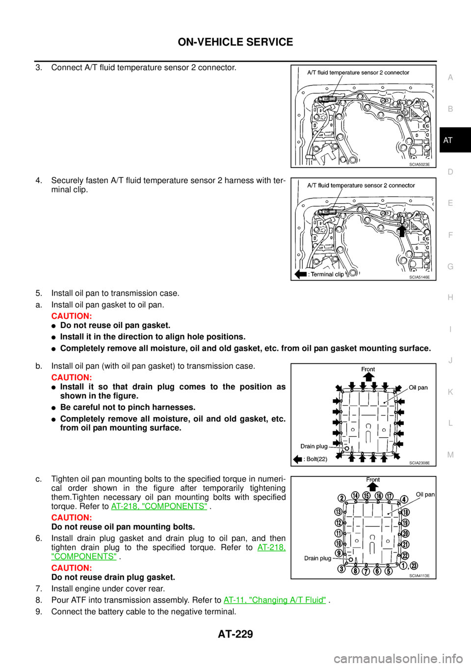
3. Connect A/T fluid temperature sensor 2 connector.
4. Securely fasten A/T fluid temperature sensor 2 harness with ter-
minal clip.
5. Install oil pan to transmission case.
a. Install oil pan gasket to oil pan.
CAUTION:
lDo not reuse oil pan gasket.
lInstall it in the direction to align hole positions.
lCompletely remove all moisture, oil and old gasket, etc. from oil pan gasket mounting surface.
b. Install oil pan (with oil pan gasket) to transmission case.
CAUTION:
lInstall it so that drain plug comes to the position as
shown in the figure.
lBe careful not to pinch harnesses.
lCompletely remove all moisture, oil and old gasket, etc.
from oil pan mounting surface.
c. Tighten oil pan mounting bolts to the specified torque in numeri-
cal order shown in the figure after temporarily tightening
them.Tighten necessary oil pan mounting bolts with specified
torque. Refer toAT- 2 1 8 , "
COMPONENTS".
CAUTION:
Do not reuse oil pan mounting bolts.
6. Install drain plug gasket and drain plug to oil pan, and then
tighten drain plug to the specified torque. Refer toAT-218,
"COMPONENTS".
CAUTION:
Do not reuse drain plug gasket.
7. Install engine under cover rear.
8. Pour ATF into transmission assembly. Refer toAT-11, "
Changing A/T Fluid".
9. Connect the battery cable to the negative terminal.
SCIA5023E
SCIA5146E
SCIA2308E
SCIA4113E
Page 238 of 3171
AT-230
ON-VEHICLE SERVICE
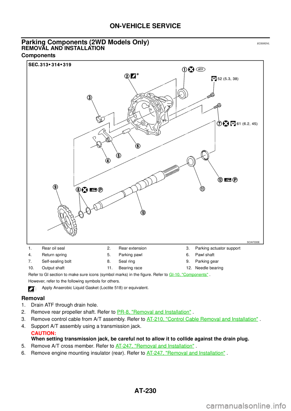
Parking Components (2WD Models Only)
ECS00GVL
REMOVAL AND INSTALLATION
Components
Removal
1. Drain ATF through drain hole.
2. Remove rear propeller shaft. Refer toPR-8, "
Removal and Installation".
3. Remove control cable from A/T assembly. Refer toAT- 2 1 0 , "
Control Cable Removal and Installation".
4. Support A/T assembly using a transmission jack.
CAUTION:
When setting transmission jack, be careful not to allow it to collide against the drain plug.
5. Remove A/T cross member. Refer toAT- 2 4 7 , "
Removal and Installation".
6. Remove engine mounting insulator (rear). Refer toAT- 2 4 7 , "
Removal and Installation".
1. Rear oil seal 2. Rear extension 3. Parking actuator support
4. Return spring 5. Parking pawl 6. Pawl shaft
7. Self-sealing bolt 8. Seal ring 9. Parking gear
10. Output shaft 11. Bearing race 12. Needle bearing
Refer to GI section to make sure icons (symbol marks) in the figure. Refer toGI-10, "
Components".
However, refer to the following symbols for others.
*:Apply Anaerobic Liquid Gasket (Loctite 518) or equivalent.
SCIA7030E
Page 239 of 3171
ON-VEHICLE SERVICE
AT-231
D
E
F
G
H
I
J
K
L
MA
B
AT
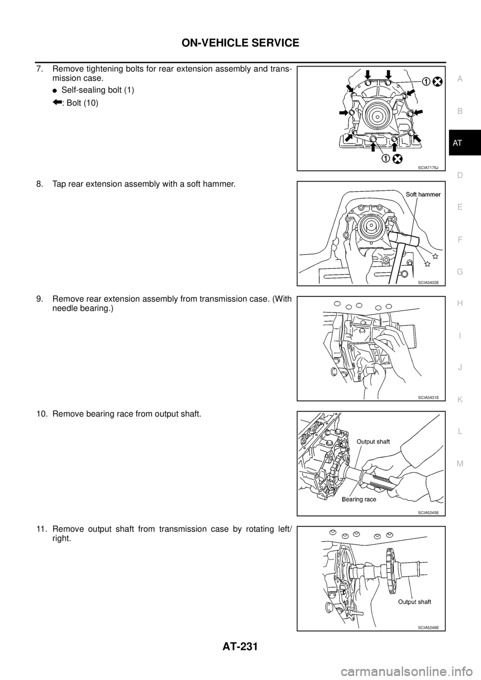
7. Remove tightening bolts for rear extension assembly and trans-
mission case.
lSelf-sealing bolt (1)
: Bolt (10)
8. Tap rear extension assembly with a soft hammer.
9. Remove rear extension assembly from transmission case. (With
needle bearing.)
10. Remove bearing race from output shaft.
11. Remove output shaft from transmission case by rotating left/
right.
SCIA7176J
SCIA3432E
SCIA3431E
SCIA5245E
SCIA5246E
Page 240 of 3171
AT-232
ON-VEHICLE SERVICE
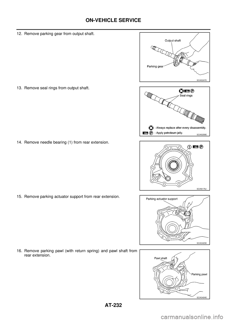
12. Remove parking gear from output shaft.
13. Remove seal rings from output shaft.
14. Remove needle bearing (1) from rear extension.
15. Remove parking actuator support from rear extension.
16. Remove parking pawl (with return spring) and pawl shaft from
rear extension.
SCIA5247E
SCIA5209E
SCIA6179J
SCIA3423E
SCIA3424E