NISSAN PICK-UP 1998 Repair Manual
Manufacturer: NISSAN, Model Year: 1998, Model line: PICK-UP, Model: NISSAN PICK-UP 1998Pages: 1659, PDF Size: 53.39 MB
Page 291 of 1659
VA
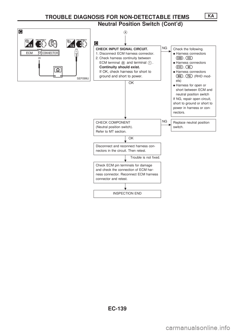
CHECK INPUT SIGNAL CIRCUIT.
1. Disconnect ECM harness connector.
2. Check harness continuity between
ECM terminal
V35and terminalV1.
Continuity should exist.
If OK, check harness for short to
ground and short to power.
OK
cNG
Check the following.
lHarness connectors
E205,E33
lHarness connectors
E101,M5
lHarness connectors
M48,F54(RHD mod-
els)
lHarness for open or
short between ECM and
neutral position switch
If NG, repair open circuit,
short to ground or short to
power in harness or con-
nectors.
CHECK COMPONENT
(Neutral position switch).
Refer to MT section.
OK
cNG
Replace neutral position
switch.
Disconnect and reconnect harness con-
nectors in the circuit. Then retest.
Trouble is not fixed.
Check ECM pin terminals for damage
and check the connection of ECM har-
ness connector. Reconnect ECM harness
connector and retest.
INSPECTION END
SEF099U
.
.
.
.
.
TROUBLE DIAGNOSIS FOR NON-DETECTABLE ITEMSKA
Neutral Position Switch (Cont'd)
EC-139
Page 292 of 1659
EVAP Canister Purge Control Solenoid Valve
COMPONENT DESCRIPTION
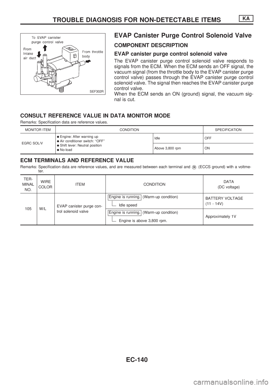
EVAP canister purge control solenoid valve
The EVAP canister purge control solenoid valve responds to
signals from the ECM. When the ECM sends an OFF signal, the
vacuum signal (from the throttle body to the EVAP canister purge
control valve) passes through the EVAP canister purge control
solenoid valve. The signal then reaches the EVAP canister purge
control valve.
When the ECM sends an ON (ground) signal, the vacuum sig-
nal is cut.
CONSULT REFERENCE VALUE IN DATA MONITOR MODE
Remarks: Specification data are reference values.
MONITOR ITEM CONDITION SPECIFICATION
EGRC SOL/V
lEngine: After warning uplAir conditioner switch: ``OFF''lShift lever: Neutral positionlNo-loadIdle OFF
Above 3,800 rpm ON
ECM TERMINALS AND REFERENCE VALUE
Remarks: Specification data are reference values, and are measured between each terminal andV39(ECCS ground) with a voltme-
ter.
TER-
MINAL
NO.WIRE
COLORITEM CONDITIONDATA
(DC voltage)
105 W/LEVAP canister purge con-
trol solenoid valveEngine is running.
(Warm-up condition)
Idle speedBATTERY VOLTAGE
(11 - 14V)
Engine is running.
(Warm-up condition)
Engine is above 3,800 rpm.Approximately 1V
SEF302R
TROUBLE DIAGNOSIS FOR NON-DETECTABLE ITEMSKA
EC-140
Page 293 of 1659
HEC358
TROUBLE DIAGNOSIS FOR NON-DETECTABLE ITEMSKA
EVAP Canister Purge Control Solenoid Valve
(Cont'd)
EC-141
Page 294 of 1659
DIAGNOSTIC PROCEDURE
INSPECTION START
CHECK OVERALL FUNCTION.
1. Perform diagnostic test mode II (Self-
diagnostic results).
Make sure that diagnostic trouble code
No. 55 is displayed.
2. Start engine and warm it up suffi-
ciently.
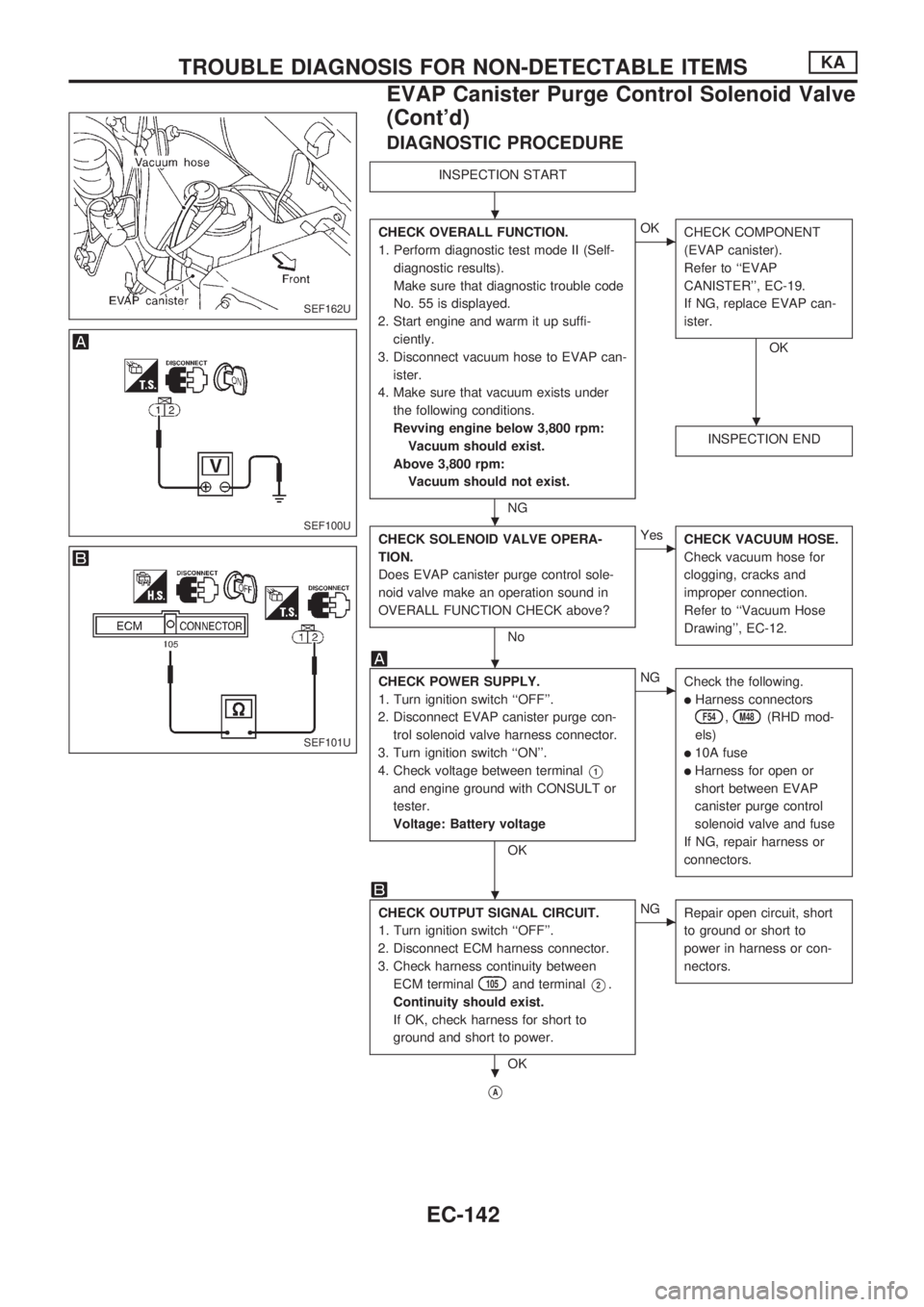
3. Disconnect vacuum hose to EVAP can-
ister.
4. Make sure that vacuum exists under
the following conditions.
Revving engine below 3,800 rpm:
Vacuum should exist.
Above 3,800 rpm:
Vacuum should not exist.
NG
cOK
CHECK COMPONENT
(EVAP canister).
Refer to ``EVAP
CANISTER'', EC-19.
If NG, replace EVAP can-
ister.
OK
INSPECTION END
CHECK SOLENOID VALVE OPERA-
TION.
Does EVAP canister purge control sole-
noid valve make an operation sound in
OVERALL FUNCTION CHECK above?
No
cYes
CHECK VACUUM HOSE.
Check vacuum hose for
clogging, cracks and
improper connection.
Refer to ``Vacuum Hose
Drawing'', EC-12.
CHECK POWER SUPPLY.
1. Turn ignition switch ``OFF''.
2. Disconnect EVAP canister purge con-
trol solenoid valve harness connector.
3. Turn ignition switch ``ON''.
4. Check voltage between terminal
V1
and engine ground with CONSULT or
tester.
Voltage: Battery voltage
OK
cNG
Check the following.
lHarness connectors
F54,M48(RHD mod-
els)
l10A fuse
lHarness for open or
short between EVAP
canister purge control
solenoid valve and fuse
If NG, repair harness or
connectors.
CHECK OUTPUT SIGNAL CIRCUIT.
1. Turn ignition switch ``OFF''.
2. Disconnect ECM harness connector.
3. Check harness continuity between
ECM terminal
105and terminalV2.
Continuity should exist.
If OK, check harness for short to
ground and short to power.
OK
cNG
Repair open circuit, short
to ground or short to
power in harness or con-
nectors.
VA
SEF162U
SEF100U
SEF101U
.
.
.
.
.
.
TROUBLE DIAGNOSIS FOR NON-DETECTABLE ITEMSKA
EVAP Canister Purge Control Solenoid Valve
(Cont'd)
EC-142
Page 295 of 1659
VA
CHECK COMPONENT.
(EVAP canister purge control solenoid
valve).
Refer to ``COMPONENT INSPECTION'',
below.
OK
cNG
Replace EVAP canister
purge control solenoid
valve.
Disconnect and reconnect harness con-
nectors in the circuit. Then retest.
Trouble is not fixed.
Check ECM pin terminals for damage
and check the connection of ECM har-
ness connector. Reconnect ECM harness
connector and retest.
INSPECTION END
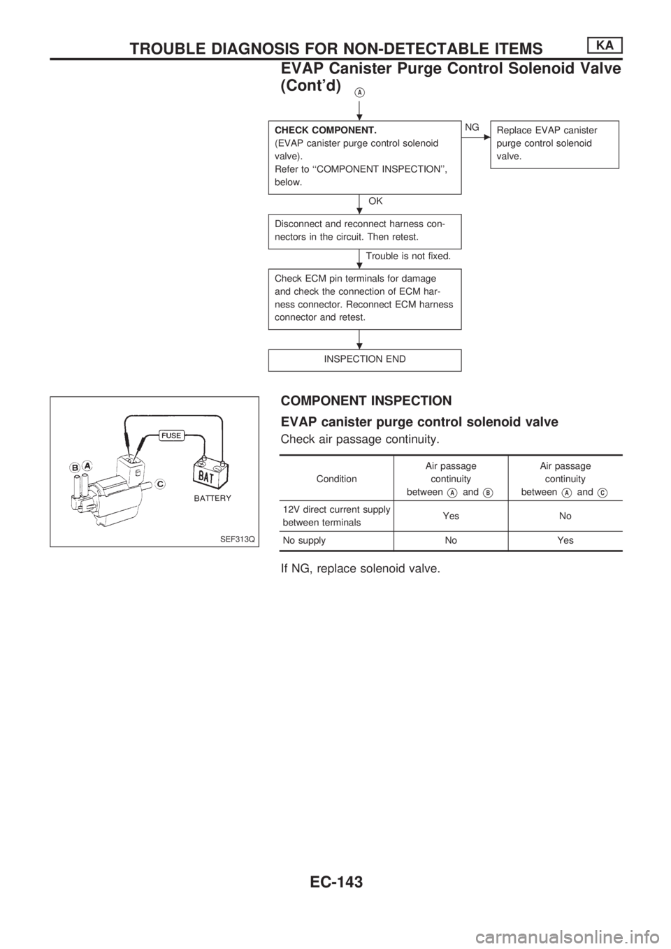
COMPONENT INSPECTION
EVAP canister purge control solenoid valve
Check air passage continuity.
ConditionAir passage
continuity
between
VAandVB
Air passage
continuity
between
VAandVC
12V direct current supply
between terminalsYes No
No supply No Yes
If NG, replace solenoid valve.
SEF313Q
.
.
.
.
TROUBLE DIAGNOSIS FOR NON-DETECTABLE ITEMSKA
EVAP Canister Purge Control Solenoid Valve
(Cont'd)
EC-143
Page 296 of 1659
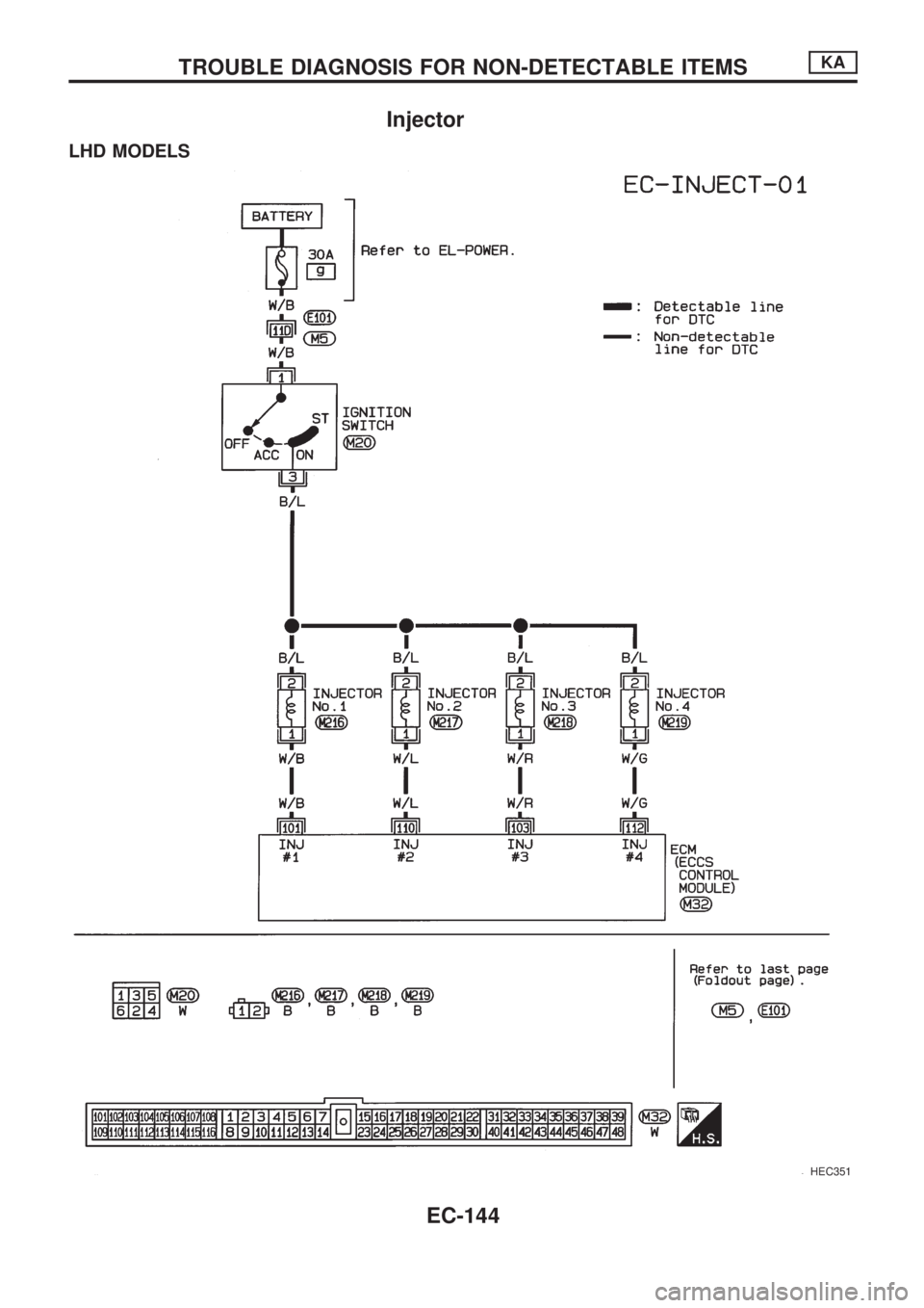
Injector
LHD MODELS
HEC351
TROUBLE DIAGNOSIS FOR NON-DETECTABLE ITEMSKA
EC-144
Page 297 of 1659
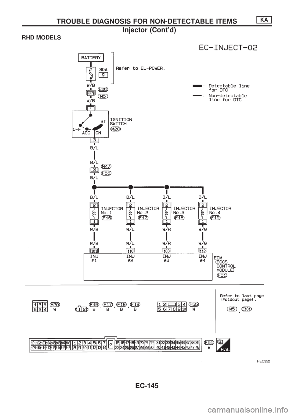
RHD MODELS
HEC352
TROUBLE DIAGNOSIS FOR NON-DETECTABLE ITEMSKA
Injector (Cont'd)
EC-145
Page 298 of 1659
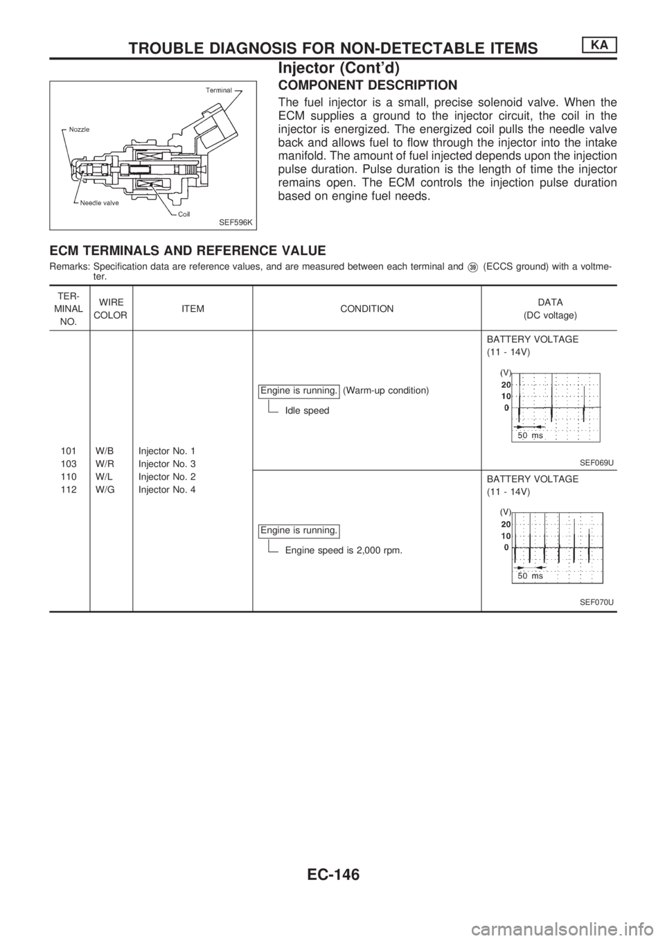
COMPONENT DESCRIPTION
The fuel injector is a small, precise solenoid valve. When the
ECM supplies a ground to the injector circuit, the coil in the
injector is energized. The energized coil pulls the needle valve
back and allows fuel to flow through the injector into the intake
manifold. The amount of fuel injected depends upon the injection
pulse duration. Pulse duration is the length of time the injector
remains open. The ECM controls the injection pulse duration
based on engine fuel needs.
ECM TERMINALS AND REFERENCE VALUE
Remarks: Specification data are reference values, and are measured between each terminal andV39(ECCS ground) with a voltme-
ter.
TER-
MINAL
NO.WIRE
COLORITEM CONDITIONDATA
(DC voltage)
101
103
110
112W/B
W/R
W/L
W/GInjector No. 1
Injector No. 3
Injector No. 2
Injector No. 4Engine is running.
(Warm-up condition)
Idle speedBATTERY VOLTAGE
(11 - 14V)
SEF069U
Engine is running.
Engine speed is 2,000 rpm.BATTERY VOLTAGE
(11 - 14V)
SEF070U
SEF596K
TROUBLE DIAGNOSIS FOR NON-DETECTABLE ITEMSKA
Injector (Cont'd)
EC-146
Page 299 of 1659
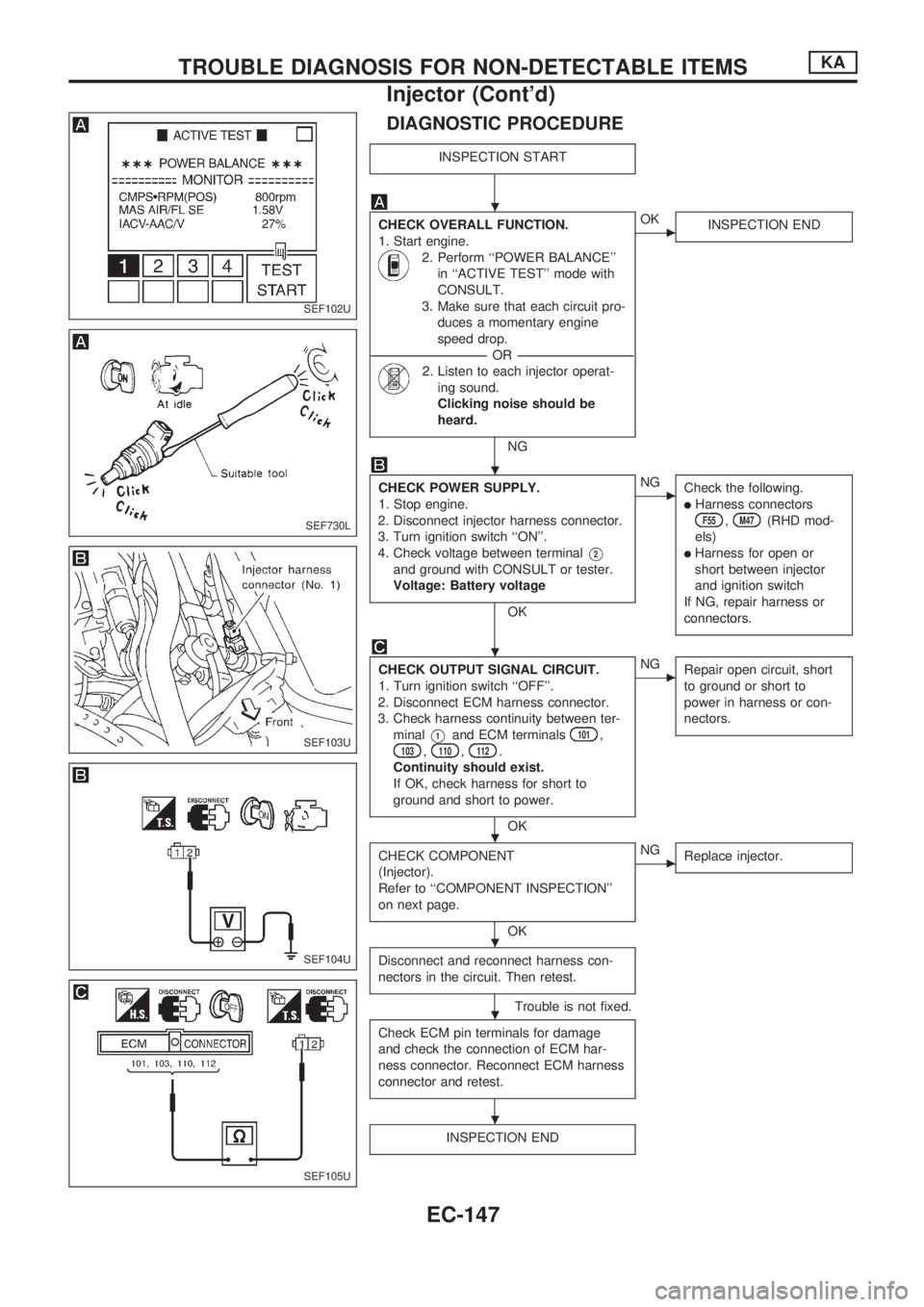
DIAGNOSTIC PROCEDURE
INSPECTION START
CHECK OVERALL FUNCTION.
1. Start engine.
2. Perform ``POWER BALANCE''
in ``ACTIVE TEST'' mode with
CONSULT.
3. Make sure that each circuit pro-
duces a momentary engine
speed drop.
----------------------------------------------------------------------------------------------------------------------------------OR----------------------------------------------------------------------------------------------------------------------------------
2. Listen to each injector operat-
ing sound.
Clicking noise should be
heard.
NG
cOK
INSPECTION END
CHECK POWER SUPPLY.
1. Stop engine.
2. Disconnect injector harness connector.
3. Turn ignition switch ``ON''.
4. Check voltage between terminal
V2
and ground with CONSULT or tester.
Voltage: Battery voltage
OK
cNG
Check the following.
lHarness connectorsF55,M47(RHD mod-
els)
lHarness for open or
short between injector
and ignition switch
If NG, repair harness or
connectors.
CHECK OUTPUT SIGNAL CIRCUIT.
1. Turn ignition switch ``OFF''.
2. Disconnect ECM harness connector.
3. Check harness continuity between ter-
minal
V1and ECM terminals101,103,110,112.
Continuity should exist.
If OK, check harness for short to
ground and short to power.
OK
cNG
Repair open circuit, short
to ground or short to
power in harness or con-
nectors.
CHECK COMPONENT
(Injector).
Refer to ``COMPONENT INSPECTION''
on next page.
OK
cNG
Replace injector.
Disconnect and reconnect harness con-
nectors in the circuit. Then retest.
Trouble is not fixed.
Check ECM pin terminals for damage
and check the connection of ECM har-
ness connector. Reconnect ECM harness
connector and retest.
INSPECTION END
SEF102U
SEF730L
SEF103U
SEF104U
SEF105U
.
.
.
.
.
.
.
TROUBLE DIAGNOSIS FOR NON-DETECTABLE ITEMSKA
Injector (Cont'd)
EC-147
Page 300 of 1659

COMPONENT INSPECTION
Injector
1. Disconnect injector harness connector.
2. Check resistance between terminals as shown in the figure.
Resistance: 10 - 14Wat 25ÉC (77ÉF)
If NG, replace injector.
SEF106U
TROUBLE DIAGNOSIS FOR NON-DETECTABLE ITEMSKA
Injector (Cont'd)
EC-148