NISSAN PICK-UP 1998 Repair Manual
Manufacturer: NISSAN, Model Year: 1998, Model line: PICK-UP, Model: NISSAN PICK-UP 1998Pages: 1659, PDF Size: 53.39 MB
Page 311 of 1659
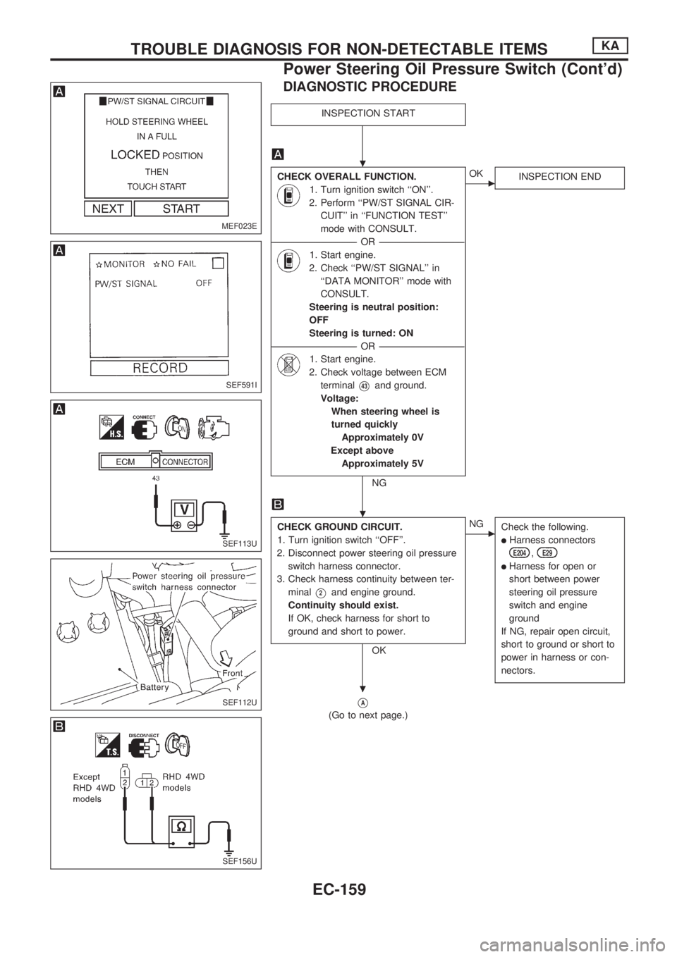
DIAGNOSTIC PROCEDURE
INSPECTION START
CHECK OVERALL FUNCTION.
1. Turn ignition switch ``ON''.
2. Perform ``PW/ST SIGNAL CIR-
CUIT'' in ``FUNCTION TEST''
mode with CONSULT.
----------------------------------------------------------------------------------------------------------------------------------OR----------------------------------------------------------------------------------------------------------------------------------
1. Start engine.
2. Check ``PW/ST SIGNAL'' in
``DATA MONITOR'' mode with
CONSULT.
Steering is neutral position:
OFF
Steering is turned: ON
----------------------------------------------------------------------------------------------------------------------------------OR----------------------------------------------------------------------------------------------------------------------------------
1. Start engine.
2. Check voltage between ECM
terminal
V43and ground.
Voltage:
When steering wheel is
turned quickly
Approximately 0V
Except above
Approximately 5V
NG
cOK
INSPECTION END
CHECK GROUND CIRCUIT.
1. Turn ignition switch ``OFF''.
2. Disconnect power steering oil pressure
switch harness connector.
3. Check harness continuity between ter-
minal
V2and engine ground.
Continuity should exist.
If OK, check harness for short to
ground and short to power.
OK
cNG
Check the following.
lHarness connectors
E204,E29
lHarness for open or
short between power
steering oil pressure
switch and engine
ground
If NG, repair open circuit,
short to ground or short to
power in harness or con-
nectors.
VA
(Go to next page.)
MEF023E
SEF591I
SEF113U
SEF112U
SEF156U
.
.
.
TROUBLE DIAGNOSIS FOR NON-DETECTABLE ITEMSKA
Power Steering Oil Pressure Switch (Cont'd)
EC-159
Page 312 of 1659
VA
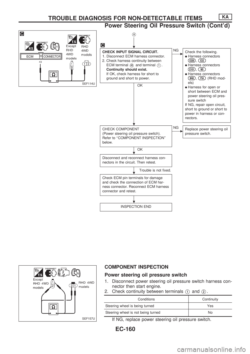
CHECK INPUT SIGNAL CIRCUIT.
1. Disconnect ECM harness connector.
2. Check harness continuity between
ECM terminal
V43and terminalV1.
Continuity should exist.
If OK, check harness for short to
ground and short to power.
OK
cNG
Check the following.
lHarness connectorsE205,E33
lHarness connectorsE101,M5
lHarness connectorsM48,F54(RHD mod-
els)
lHarness for open or
short between ECM and
power steering oil pres-
sure switch
If NG, repair open circuit,
short to ground or short to
power in harness or con-
nectors.
CHECK COMPONENT
(Power steering oil pressure switch).
Refer to ``COMPONENT INSPECTION''
below.
OK
cNG
Replace power steering oil
pressure switch.
Disconnect and reconnect harness con-
nectors in the circuit. Then retest.
Trouble is not fixed.
Check ECM pin terminals for damage
and check the connection of ECM har-
ness connector. Reconnect ECM harness
connector and retest.
INSPECTION END
COMPONENT INSPECTION
Power steering oil pressure switch
1. Disconnect power steering oil pressure switch harness con-
nector then start engine.
2. Check continuity between terminals
V1andV2.
Conditions Continuity
Steering wheel is being turned Yes
Steering wheel is not being turned No
If NG, replace power steering oil pressure switch.
SEF114U
SEF157U
.
.
.
.
.
TROUBLE DIAGNOSIS FOR NON-DETECTABLE ITEMSKA
Power Steering Oil Pressure Switch (Cont'd)
EC-160
Page 313 of 1659
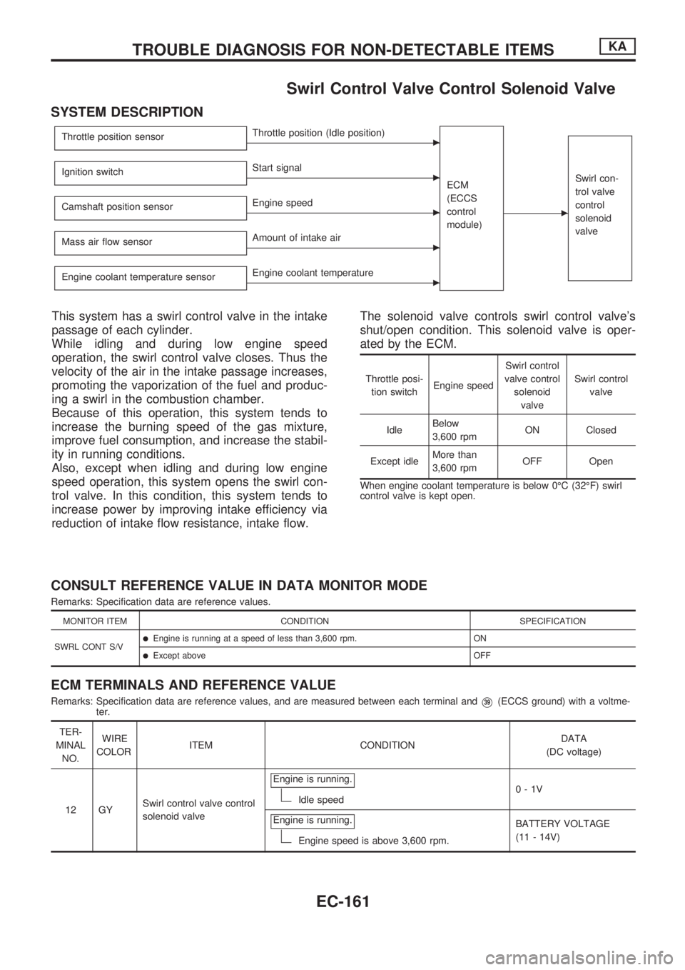
Swirl Control Valve Control Solenoid Valve
SYSTEM DESCRIPTION
Throttle position sensorcThrottle position (Idle position)
ECM
(ECCS
control
module)
c
Swirl con-
trol valve
control
solenoid
valveIgnition switchcStart signal
Camshaft position sensor
cEngine speed
Mass air flow sensor
cAmount of intake air
Engine coolant temperature sensor
cEngine coolant temperature
This system has a swirl control valve in the intake
passage of each cylinder.
While idling and during low engine speed
operation, the swirl control valve closes. Thus the
velocity of the air in the intake passage increases,
promoting the vaporization of the fuel and produc-
ing a swirl in the combustion chamber.
Because of this operation, this system tends to
increase the burning speed of the gas mixture,
improve fuel consumption, and increase the stabil-
ity in running conditions.
Also, except when idling and during low engine
speed operation, this system opens the swirl con-
trol valve. In this condition, this system tends to
increase power by improving intake efficiency via
reduction of intake flow resistance, intake flow.The solenoid valve controls swirl control valve's
shut/open condition. This solenoid valve is oper-
ated by the ECM.
Throttle posi-
tion switchEngine speedSwirl control
valve control
solenoid
valveSwirl control
valve
IdleBelow
3,600 rpmON Closed
Except idleMore than
3,600 rpmOFF Open
When engine coolant temperature is below 0ÉC (32ÉF) swirl
control valve is kept open.
CONSULT REFERENCE VALUE IN DATA MONITOR MODE
Remarks: Specification data are reference values.
MONITOR ITEM CONDITION SPECIFICATION
SWRL CONT S/V
lEngine is running at a speed of less than 3,600 rpm. ON
lExcept above OFF
ECM TERMINALS AND REFERENCE VALUE
Remarks: Specification data are reference values, and are measured between each terminal andV39(ECCS ground) with a voltme-
ter.
TER-
MINAL
NO.WIRE
COLORITEM CONDITIONDATA
(DC voltage)
12 GYSwirl control valve control
solenoid valveEngine is running.
Idle speed0-1V
Engine is running.
Engine speed is above 3,600 rpm.BATTERY VOLTAGE
(11 - 14V)
TROUBLE DIAGNOSIS FOR NON-DETECTABLE ITEMSKA
EC-161
Page 314 of 1659
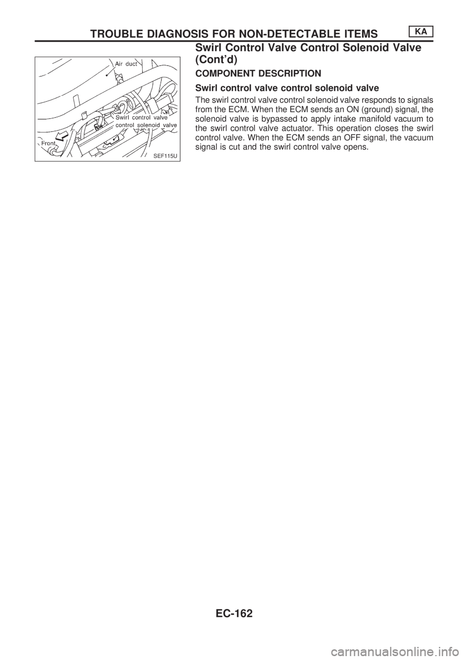
COMPONENT DESCRIPTION
Swirl control valve control solenoid valve
The swirl control valve control solenoid valve responds to signals
from the ECM. When the ECM sends an ON (ground) signal, the
solenoid valve is bypassed to apply intake manifold vacuum to
the swirl control valve actuator. This operation closes the swirl
control valve. When the ECM sends an OFF signal, the vacuum
signal is cut and the swirl control valve opens.
SEF115U
TROUBLE DIAGNOSIS FOR NON-DETECTABLE ITEMSKA
Swirl Control Valve Control Solenoid Valve
(Cont'd)
EC-162
Page 315 of 1659
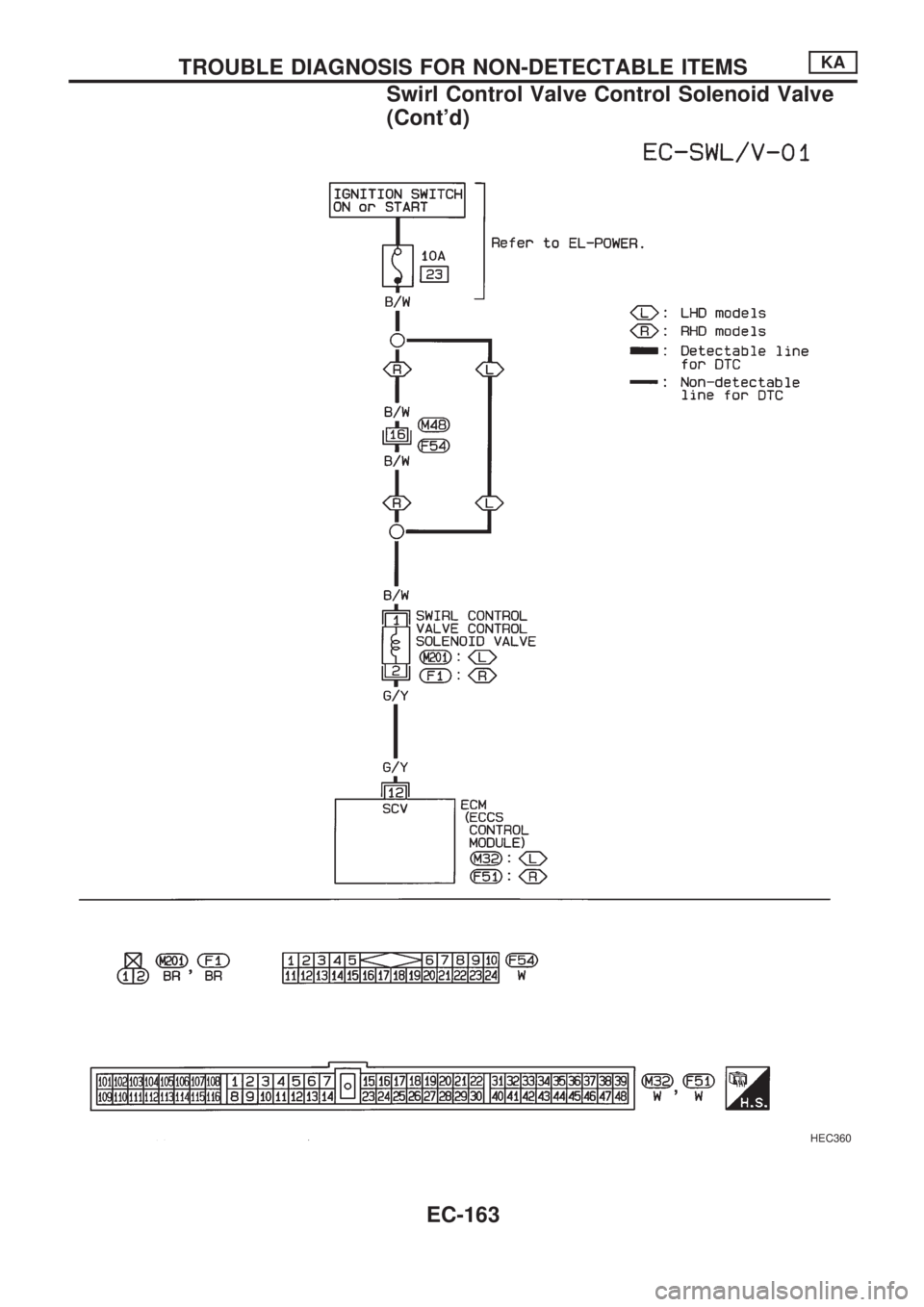
HEC360
TROUBLE DIAGNOSIS FOR NON-DETECTABLE ITEMSKA
Swirl Control Valve Control Solenoid Valve
(Cont'd)
EC-163
Page 316 of 1659
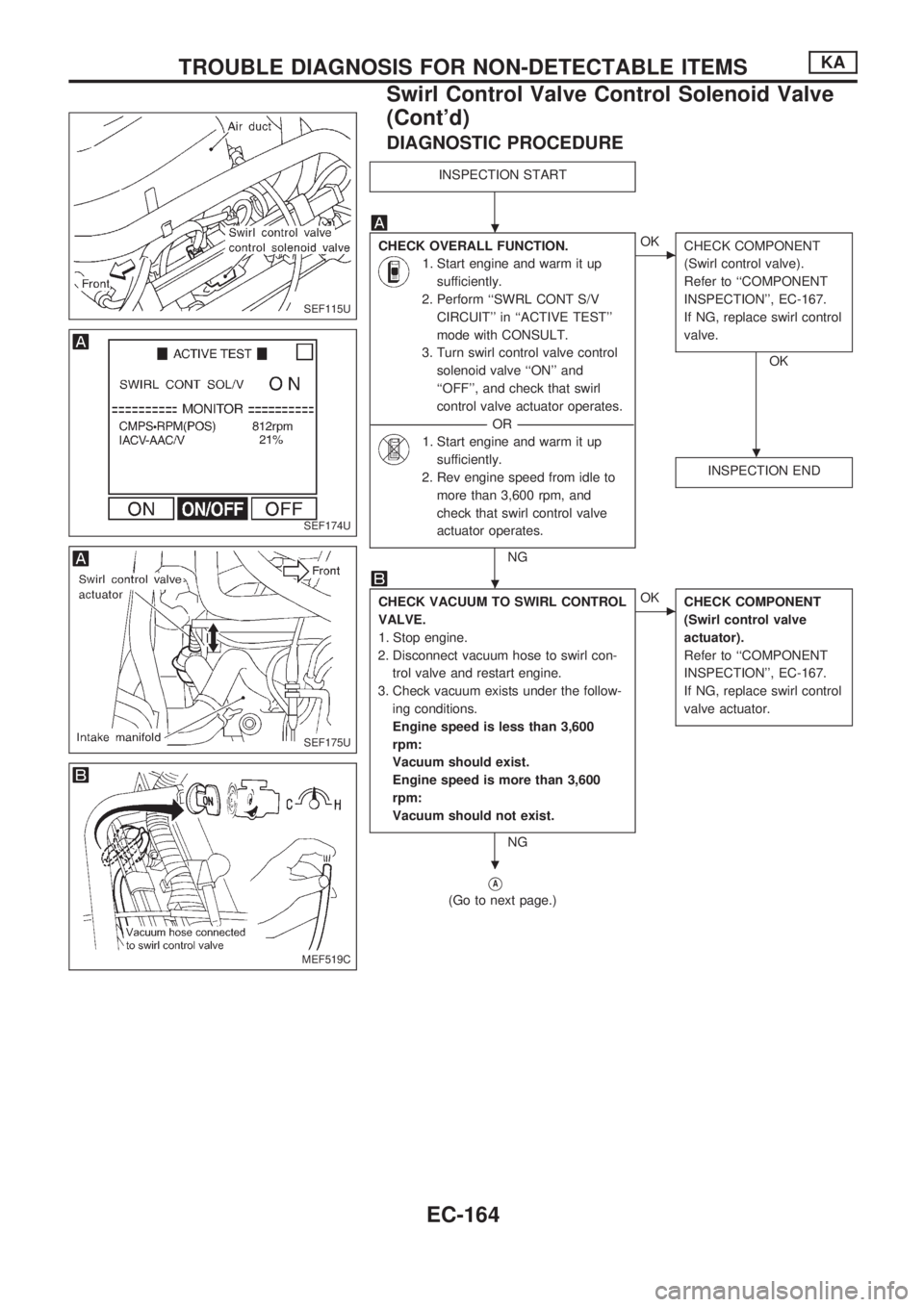
DIAGNOSTIC PROCEDURE
INSPECTION START
CHECK OVERALL FUNCTION.
1. Start engine and warm it up
sufficiently.
2. Perform ``SWRL CONT S/V
CIRCUIT'' in ``ACTIVE TEST''
mode with CONSULT.
3. Turn swirl control valve control
solenoid valve ``ON'' and
``OFF'', and check that swirl
control valve actuator operates.
----------------------------------------------------------------------------------------------------------------------------------OR----------------------------------------------------------------------------------------------------------------------------------
1. Start engine and warm it up
sufficiently.
2. Rev engine speed from idle to
more than 3,600 rpm, and
check that swirl control valve
actuator operates.
NG
cOK
CHECK COMPONENT
(Swirl control valve).
Refer to ``COMPONENT
INSPECTION'', EC-167.
If NG, replace swirl control
valve.
OK
INSPECTION END
CHECK VACUUM TO SWIRL CONTROL
VALVE.
1. Stop engine.
2. Disconnect vacuum hose to swirl con-
trol valve and restart engine.
3. Check vacuum exists under the follow-
ing conditions.
Engine speed is less than 3,600
rpm:
Vacuum should exist.
Engine speed is more than 3,600
rpm:
Vacuum should not exist.
NG
cOK
CHECK COMPONENT
(Swirl control valve
actuator).
Refer to ``COMPONENT
INSPECTION'', EC-167.
If NG, replace swirl control
valve actuator.
VA
(Go to next page.)
SEF115U
SEF174U
SEF175U
MEF519C
.
.
.
.
TROUBLE DIAGNOSIS FOR NON-DETECTABLE ITEMSKA
Swirl Control Valve Control Solenoid Valve
(Cont'd)
EC-164
Page 317 of 1659
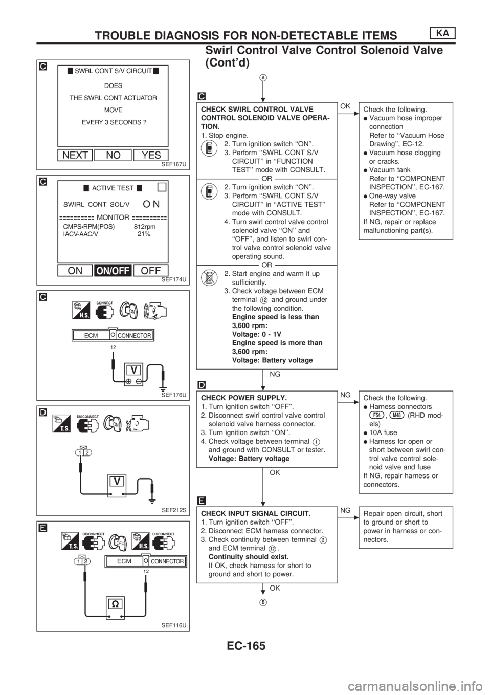
VA
CHECK SWIRL CONTROL VALVE
CONTROL SOLENOID VALVE OPERA-
TION.
1. Stop engine.
2. Turn ignition switch ``ON''.
3. Perform ``SWRL CONT S/V
CIRCUIT'' in ``FUNCTION
TEST'' mode with CONSULT.
----------------------------------------------------------------------------------------------------------------------------------OR----------------------------------------------------------------------------------------------------------------------------------
2. Turn ignition switch ``ON''.
3. Perform ``SWRL CONT S/V
CIRCUIT'' in ``ACTIVE TEST''
mode with CONSULT.
4. Turn swirl control valve control
solenoid valve ``ON'' and
``OFF'', and listen to swirl con-
trol valve control solenoid valve
operating sound.
----------------------------------------------------------------------------------------------------------------------------------OR----------------------------------------------------------------------------------------------------------------------------------
2. Start engine and warm it up
sufficiently.
3. Check voltage between ECM
terminal
V12and ground under
the following condition.
Engine speed is less than
3,600 rpm:
Voltage:0-1V
Engine speed is more than
3,600 rpm:
Voltage: Battery voltage
NG
cOK
Check the following.
lVacuum hose improper
connection
Refer to ``Vacuum Hose
Drawing'', EC-12.
lVacuum hose clogging
or cracks.
lVacuum tank
Refer to ``COMPONENT
INSPECTION'', EC-167.
lOne-way valve
Refer to ``COMPONENT
INSPECTION'', EC-167.
If NG, repair or replace
malfunctioning part(s).
CHECK POWER SUPPLY.
1. Turn ignition switch ``OFF''.
2. Disconnect swirl control valve control
solenoid valve harness connector.
3. Turn ignition switch ``ON''.
4. Check voltage between terminal
V1
and ground with CONSULT or tester.
Voltage: Battery voltage
OK
cNG
Check the following.
lHarness connectorsF54,M48(RHD mod-
els)
l10A fuse
lHarness for open or
short between swirl con-
trol valve control sole-
noid valve and fuse
If NG, repair harness or
connectors.
CHECK INPUT SIGNAL CIRCUIT.
1. Turn ignition switch ``OFF''.
2. Disconnect ECM harness connector.
3. Check continuity between terminal
V2
and ECM terminalV12.
Continuity should exist.
If OK, check harness for short to
ground and short to power.
OK
cNG
Repair open circuit, short
to ground or short to
power in harness or con-
nectors.
VB
SEF167U
SEF174U
SEF176U
SEF212S
SEF116U
.
.
.
.
TROUBLE DIAGNOSIS FOR NON-DETECTABLE ITEMSKA
Swirl Control Valve Control Solenoid Valve
(Cont'd)
EC-165
Page 318 of 1659

VB
Disconnect and reconnect harness con-
nectors in the circuit. Then retest.
Trouble is not fixed.
Check ECM pin terminals for damage
and check the connection for ECM har-
ness connector. Reconnect ECM harness
connector and retest.
INSPECTION END
.
.
.
TROUBLE DIAGNOSIS FOR NON-DETECTABLE ITEMSKA
Swirl Control Valve Control Solenoid Valve
(Cont'd)
EC-166
Page 319 of 1659
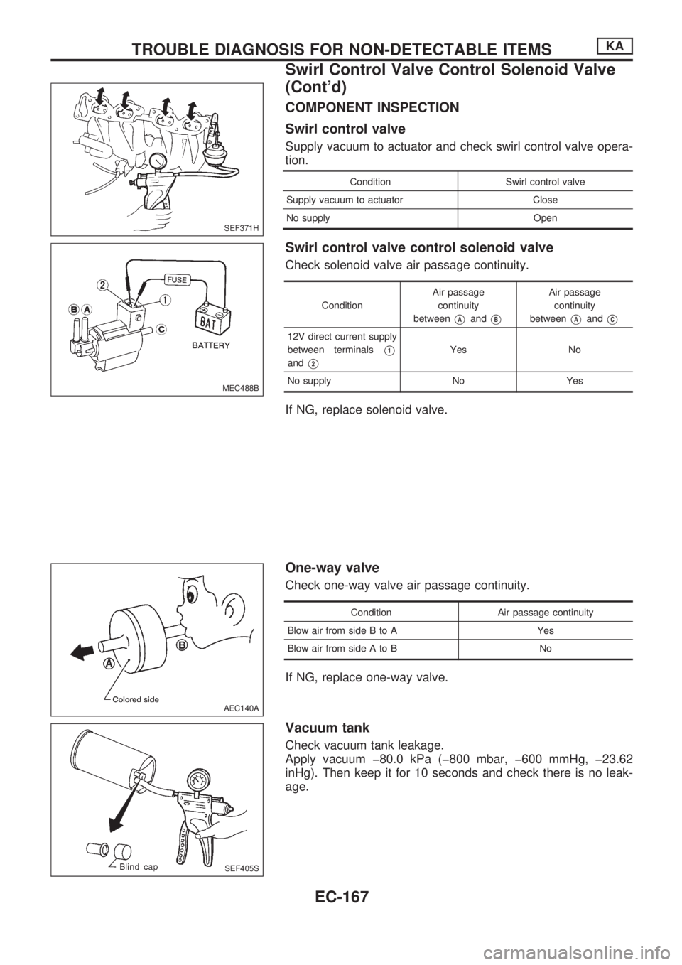
COMPONENT INSPECTION
Swirl control valve
Supply vacuum to actuator and check swirl control valve opera-
tion.
Condition Swirl control valve
Supply vacuum to actuator Close
No supply Open
Swirl control valve control solenoid valve
Check solenoid valve air passage continuity.
ConditionAir passage
continuity
between
VAandVB
Air passage
continuity
between
VAandVC
12V direct current supply
between terminals
V1
andV2
Yes No
No supply No Yes
If NG, replace solenoid valve.
One-way valve
Check one-way valve air passage continuity.
Condition Air passage continuity
Blow air from side B to A Yes
Blow air from side A to B No
If NG, replace one-way valve.
Vacuum tank
Check vacuum tank leakage.
Apply vacuum þ80.0 kPa (þ800 mbar, þ600 mmHg, þ23.62
inHg). Then keep it for 10 seconds and check there is no leak-
age.
SEF371H
MEC488B
AEC140A
SEF405S
TROUBLE DIAGNOSIS FOR NON-DETECTABLE ITEMSKA
Swirl Control Valve Control Solenoid Valve
(Cont'd)
EC-167
Page 320 of 1659
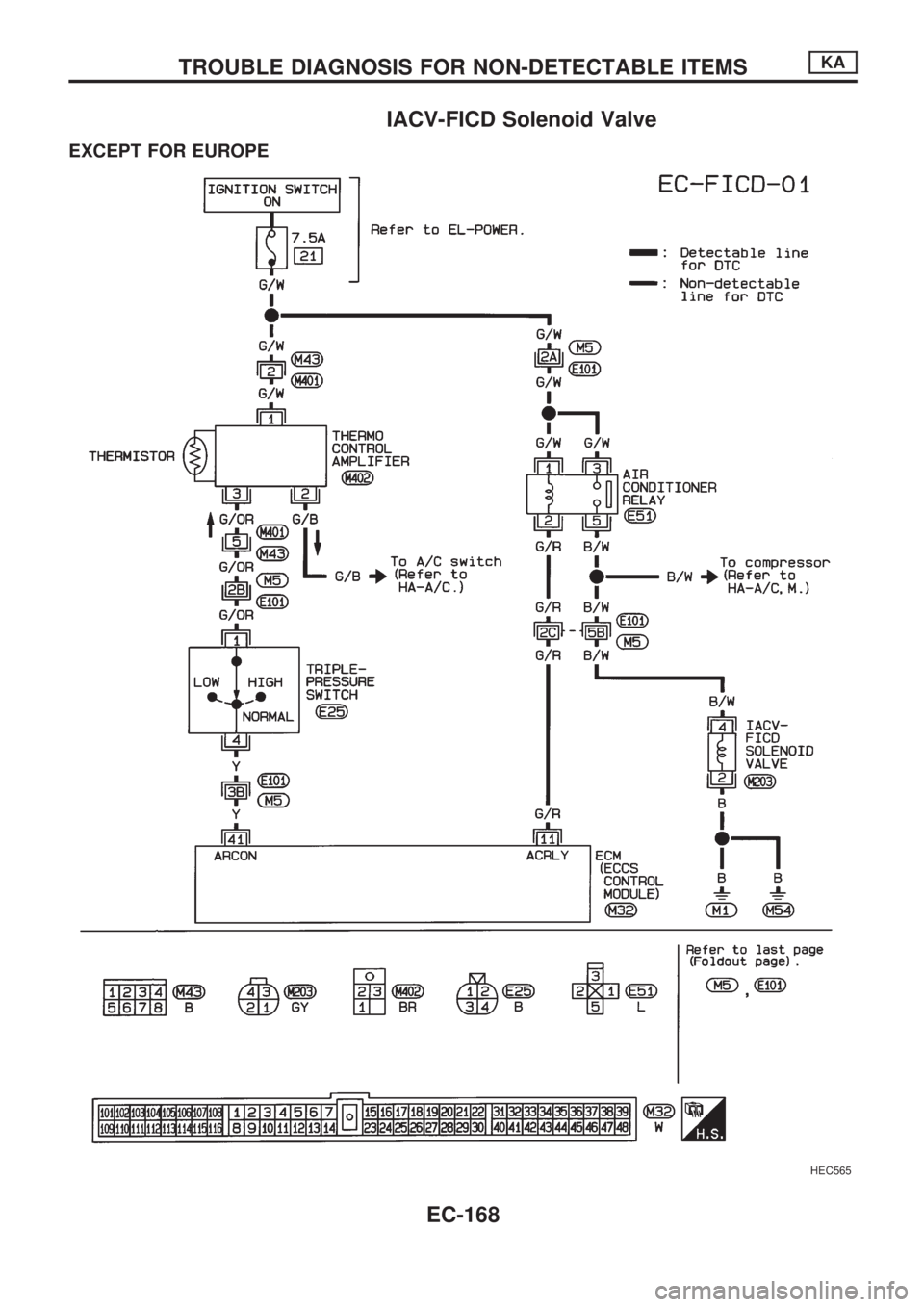
IACV-FICD Solenoid Valve
EXCEPT FOR EUROPE
HEC565
TROUBLE DIAGNOSIS FOR NON-DETECTABLE ITEMSKA
EC-168