NISSAN PICK-UP 1998 Repair Manual
PICK-UP 1998
NISSAN
NISSAN
https://www.carmanualsonline.info/img/5/57374/w960_57374-0.png
NISSAN PICK-UP 1998 Repair Manual
Trending: alternator belt, brake, el 133, brake sensor, spare tire, towing, tires
Page 951 of 1659
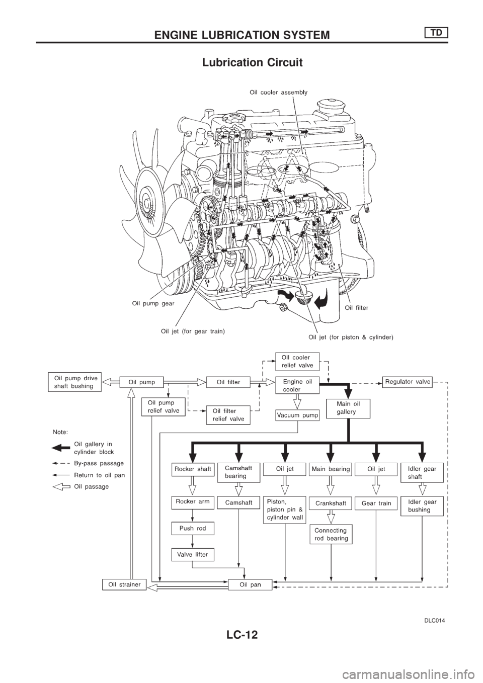
Lubrication Circuit
DLC014
ENGINE LUBRICATION SYSTEMTD
LC-12
Page 952 of 1659
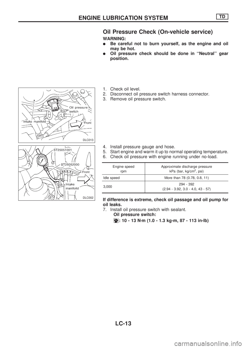
Oil Pressure Check (On-vehicle service)
WARNING:
lBe careful not to burn yourself, as the engine and oil
may be hot.
lOil pressure check should be done in ``Neutral'' gear
position.
1. Check oil level.
2. Disconnect oil pressure switch harness connector.
3. Remove oil pressure switch.
4. Install pressure gauge and hose.
5. Start engine and warm it up to normal operating temperature.
6. Check oil pressure with engine running under no-load.
Engine speed
rpmApproximate discharge pressure
kPa (bar, kg/cm2, psi)
Idle speed More than 78 (0.78, 0.8, 11)
3,000294 - 392
(2.94 - 3.92, 3.0 - 4.0, 43 - 57)
If difference is extreme, check oil passage and oil pump for
oil leaks.
7. Install oil pressure switch with sealant.
Oil pressure switch:
:10-13Nzm (1.0 - 1.3 kg-m, 87 - 113 in-lb)
DLC013
DLC002
ENGINE LUBRICATION SYSTEMTD
LC-13
Page 953 of 1659
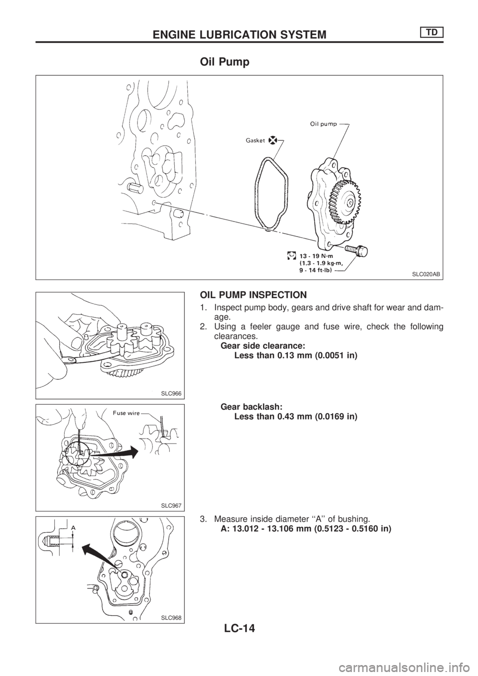
Oil Pump
OIL PUMP INSPECTION
1. Inspect pump body, gears and drive shaft for wear and dam-
age.
2. Using a feeler gauge and fuse wire, check the following
clearances.
Gear side clearance:
Less than 0.13 mm (0.0051 in)
Gear backlash:
Less than 0.43 mm (0.0169 in)
3. Measure inside diameter ``A'' of bushing.
A: 13.012 - 13.106 mm (0.5123 - 0.5160 in)
SLC020AB
SLC966
SLC967
SLC968
ENGINE LUBRICATION SYSTEMTD
LC-14
Page 954 of 1659
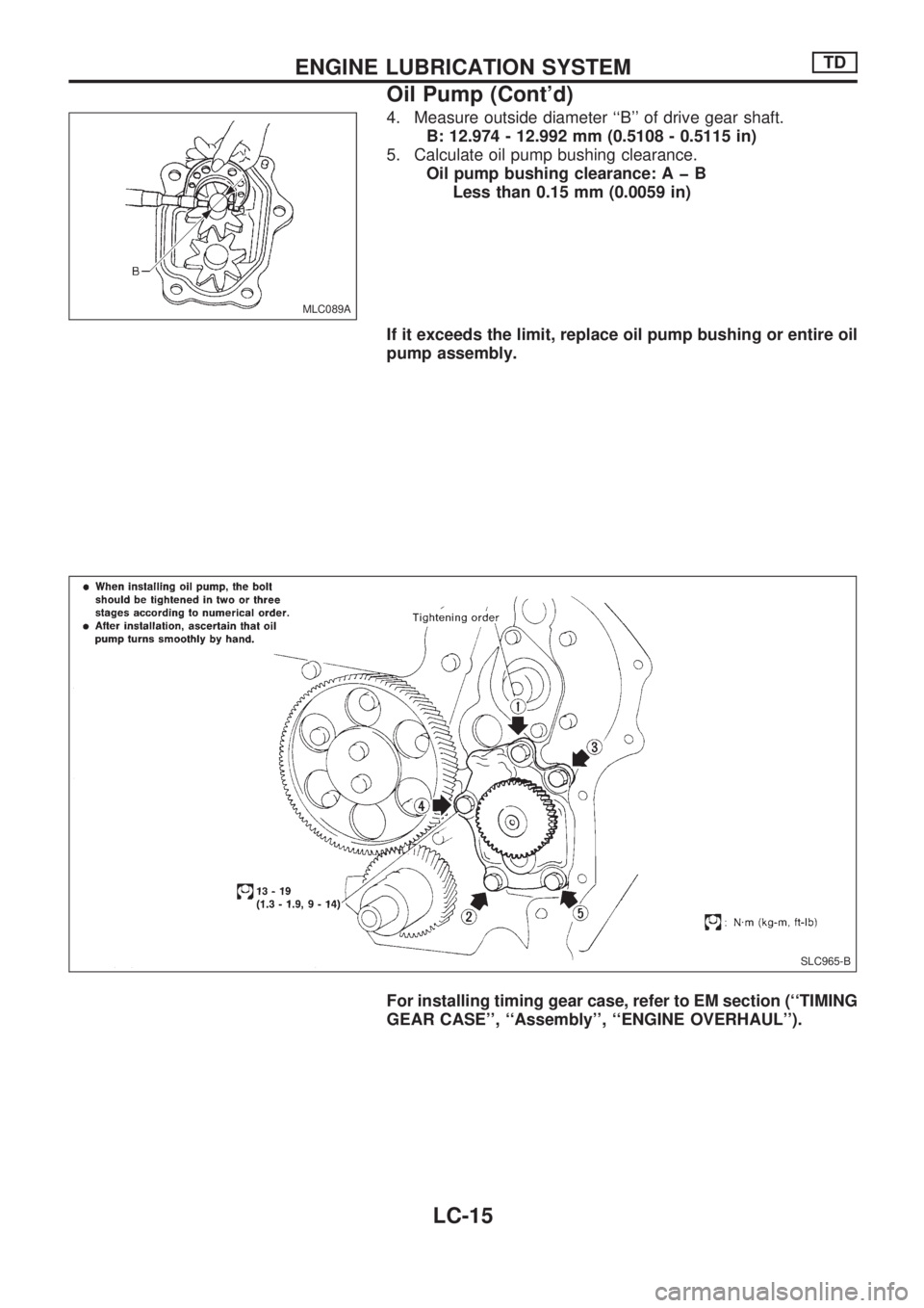
4. Measure outside diameter ``B'' of drive gear shaft.
B: 12.974 - 12.992 mm (0.5108 - 0.5115 in)
5. Calculate oil pump bushing clearance.
Oil pump bushing clearance:AþB
Less than 0.15 mm (0.0059 in)
If it exceeds the limit, replace oil pump bushing or entire oil
pump assembly.
For installing timing gear case, refer to EM section (``TIMING
GEAR CASE'', ``Assembly'', ``ENGINE OVERHAUL'').
MLC089A
SLC965-B
ENGINE LUBRICATION SYSTEMTD
Oil Pump (Cont'd)
LC-15
Page 955 of 1659
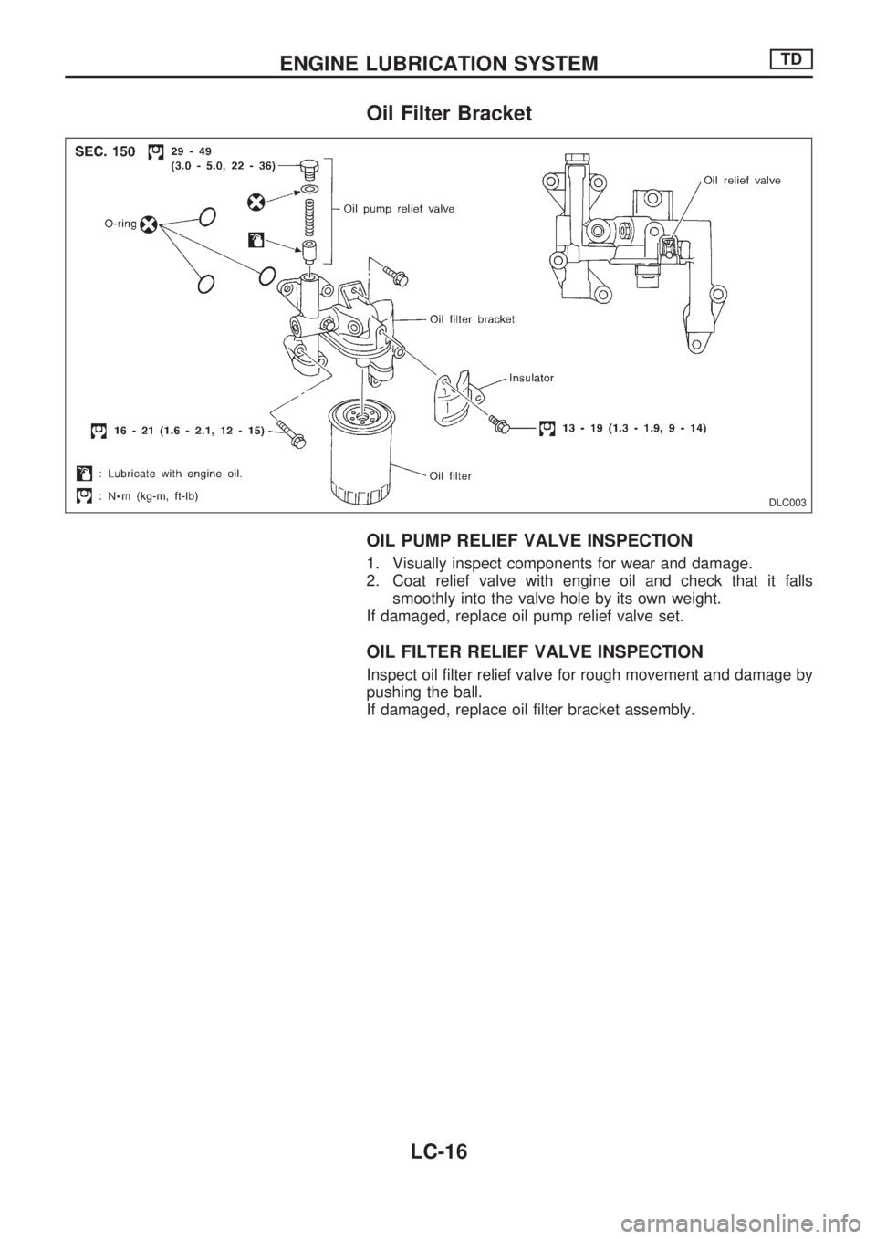
Oil Filter Bracket
OIL PUMP RELIEF VALVE INSPECTION
1. Visually inspect components for wear and damage.
2. Coat relief valve with engine oil and check that it falls
smoothly into the valve hole by its own weight.
If damaged, replace oil pump relief valve set.
OIL FILTER RELIEF VALVE INSPECTION
Inspect oil filter relief valve for rough movement and damage by
pushing the ball.
If damaged, replace oil filter bracket assembly.
DLC003
ENGINE LUBRICATION SYSTEMTD
LC-16
Page 956 of 1659
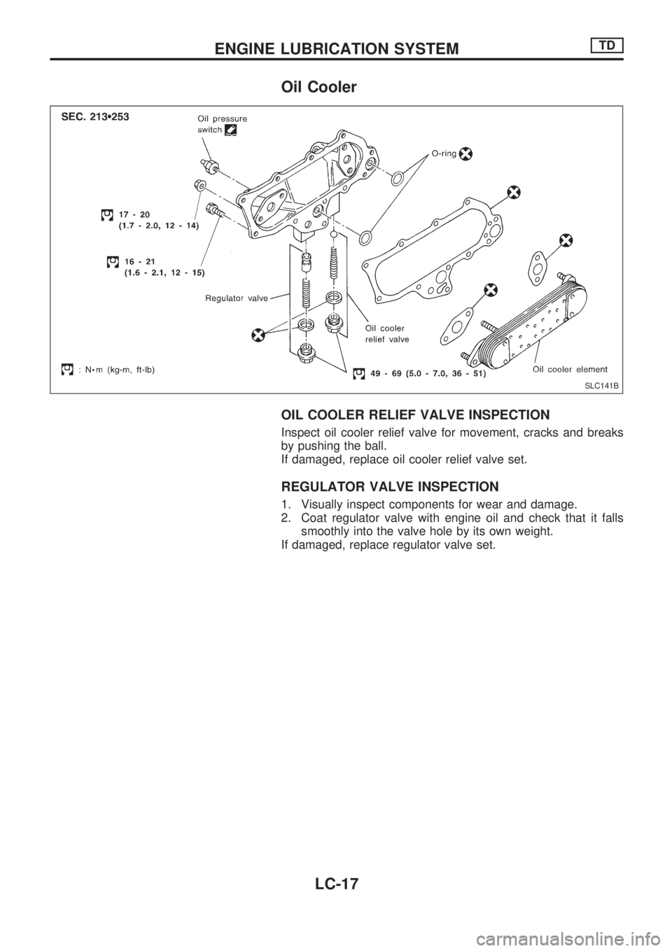
Oil Cooler
OIL COOLER RELIEF VALVE INSPECTION
Inspect oil cooler relief valve for movement, cracks and breaks
by pushing the ball.
If damaged, replace oil cooler relief valve set.
REGULATOR VALVE INSPECTION
1. Visually inspect components for wear and damage.
2. Coat regulator valve with engine oil and check that it falls
smoothly into the valve hole by its own weight.
If damaged, replace regulator valve set.
SLC141B
ENGINE LUBRICATION SYSTEMTD
LC-17
Page 957 of 1659
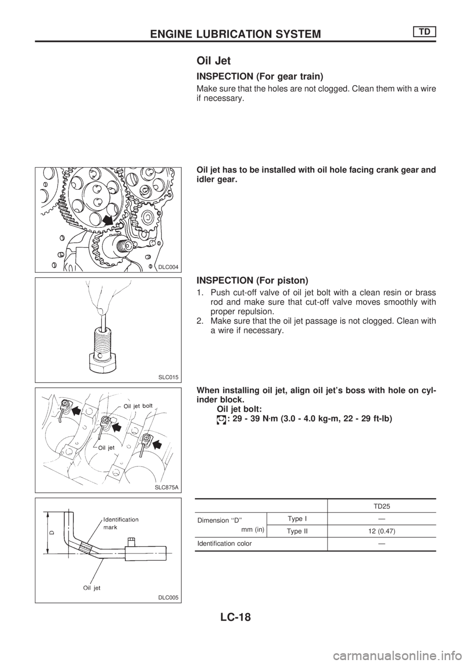
Oil Jet
INSPECTION (For gear train)
Make sure that the holes are not clogged. Clean them with a wire
if necessary.
Oil jet has to be installed with oil hole facing crank gear and
idler gear.
INSPECTION (For piston)
1. Push cut-off valve of oil jet bolt with a clean resin or brass
rod and make sure that cut-off valve moves smoothly with
proper repulsion.
2. Make sure that the oil jet passage is not clogged. Clean with
a wire if necessary.
When installing oil jet, align oil jet's boss with hole on cyl-
inder block.
Oil jet bolt:
:29-39Nzm (3.0 - 4.0 kg-m, 22 - 29 ft-lb)
TD25
Dimension ``D''
mm (in)Type I Ð
Type II 12 (0.47)
Identification color Ð
DLC004
SLC015
SLC875A
DLC005
ENGINE LUBRICATION SYSTEMTD
LC-18
Page 958 of 1659
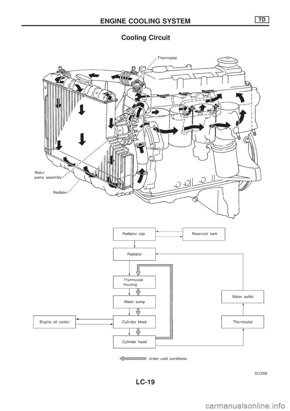
Cooling Circuit
DLC006
ENGINE COOLING SYSTEMTD
LC-19
Page 959 of 1659
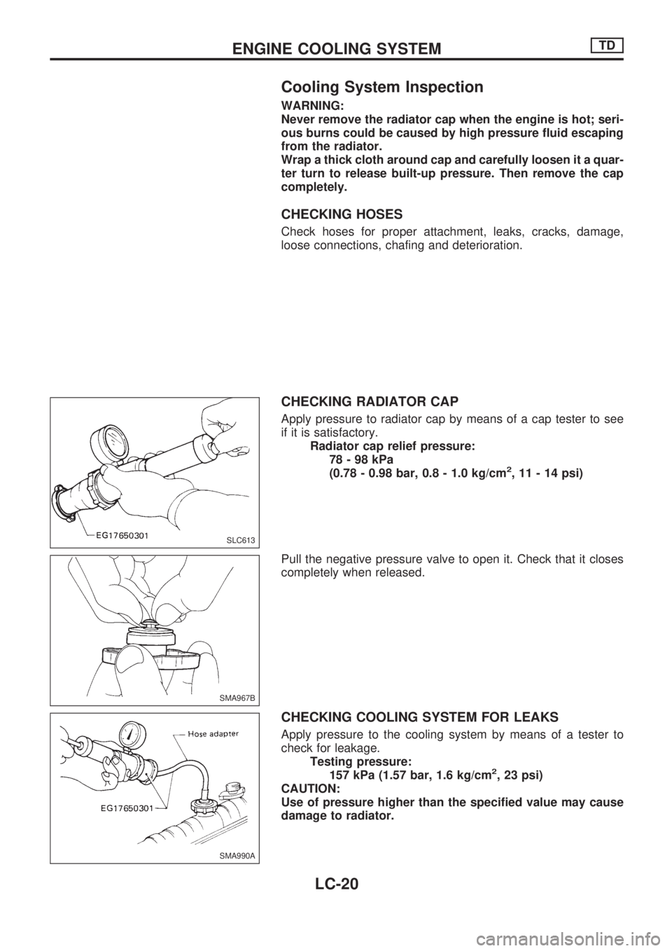
Cooling System Inspection
WARNING:
Never remove the radiator cap when the engine is hot; seri-
ous burns could be caused by high pressure fluid escaping
from the radiator.
Wrap a thick cloth around cap and carefully loosen it a quar-
ter turn to release built-up pressure. Then remove the cap
completely.
CHECKING HOSES
Check hoses for proper attachment, leaks, cracks, damage,
loose connections, chafing and deterioration.
CHECKING RADIATOR CAP
Apply pressure to radiator cap by means of a cap tester to see
if it is satisfactory.
Radiator cap relief pressure:
78-98kPa
(0.78 - 0.98 bar, 0.8 - 1.0 kg/cm
2, 11 - 14 psi)
Pull the negative pressure valve to open it. Check that it closes
completely when released.
CHECKING COOLING SYSTEM FOR LEAKS
Apply pressure to the cooling system by means of a tester to
check for leakage.
Testing pressure:
157 kPa (1.57 bar, 1.6 kg/cm
2, 23 psi)
CAUTION:
Use of pressure higher than the specified value may cause
damage to radiator.
SLC613
SMA967B
SMA990A
ENGINE COOLING SYSTEMTD
LC-20
Page 960 of 1659
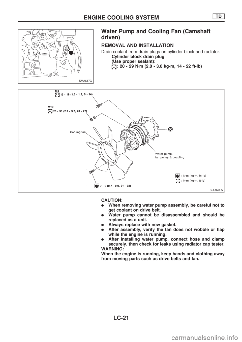
Water Pump and Cooling Fan (Camshaft
driven)
REMOVAL AND INSTALLATION
Drain coolant from drain plugs on cylinder block and radiator.
Cylinder block drain plug
(Use proper sealant):
:20-29Nzm (2.0 - 3.0 kg-m, 14 - 22 ft-lb)
CAUTION:
lWhen removing water pump assembly, be careful not to
get coolant on drive belt.
lWater pump cannot be disassembled and should be
replaced as a unit.
lAlways replace with new gasket.
lAfter assembly, verify the fan does not wobble or flap
while the engine is running.
lAfter installing water pump, connect hose and clamp
securely, then check for leaks using radiator cap tester.
WARNING:
When the engine is running, keep hands and clothing away
from moving parts such as drive belts and fan.
SMA617C
SLC978-A
ENGINE COOLING SYSTEMTD
LC-21
Trending: fuel filter location, heating, coolant, fuse box, compression ratio, EL 132, adding oil
