NISSAN PRIMERA 1999 Electronic Repair Manual
Manufacturer: NISSAN, Model Year: 1999, Model line: PRIMERA, Model: NISSAN PRIMERA 1999Pages: 2267, PDF Size: 35.74 MB
Page 2181 of 2267
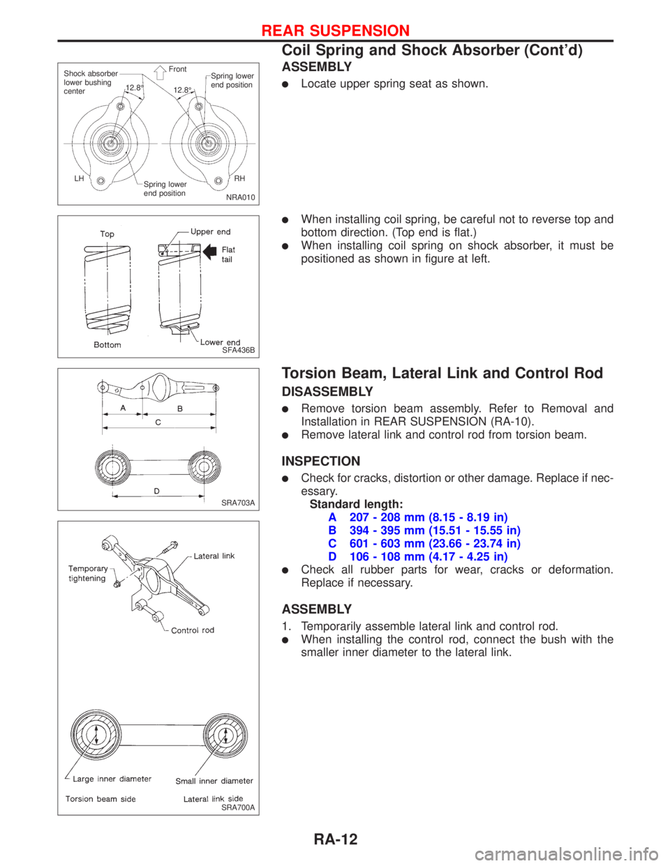
ASSEMBLY
lLocate upper spring seat as shown.
lWhen installing coil spring, be careful not to reverse top and
bottom direction. (Top end is flat.)
lWhen installing coil spring on shock absorber, it must be
positioned as shown in figure at left.
Torsion Beam, Lateral Link and Control Rod
DISASSEMBLY
lRemove torsion beam assembly. Refer to Removal and
Installation in REAR SUSPENSION (RA-10).
lRemove lateral link and control rod from torsion beam.
INSPECTION
lCheck for cracks, distortion or other damage. Replace if nec-
essary.
Standard length:
A 207 - 208 mm (8.15 - 8.19 in)
B 394 - 395 mm (15.51 - 15.55 in)
C 601 - 603 mm (23.66 - 23.74 in)
D 106 - 108 mm (4.17 - 4.25 in)
lCheck all rubber parts for wear, cracks or deformation.
Replace if necessary.
ASSEMBLY
1. Temporarily assemble lateral link and control rod.
lWhen installing the control rod, connect the bush with the
smaller inner diameter to the lateral link.
NRA010 Shock absorber
lower bushing
centerSpring lower
end position
Spring lower
end positionRH LH12.8É
12.8É Front
SFA436B
SRA703A
SRA700A
REAR SUSPENSION
Coil Spring and Shock Absorber (Cont'd)
RA-12
Page 2182 of 2267
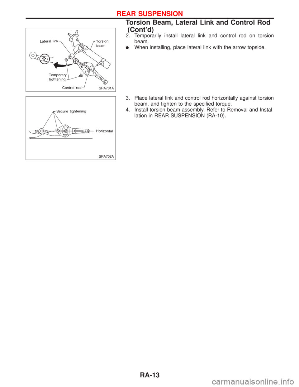
2. Temporarily install lateral link and control rod on torsion
beam.
lWhen installing, place lateral link with the arrow topside.
3. Place lateral link and control rod horizontally against torsion
beam, and tighten to the specified torque.
4. Install torsion beam assembly. Refer to Removal and Instal-
lation in REAR SUSPENSION (RA-10).
SRA701A
SRA702A
REAR SUSPENSION
Torsion Beam, Lateral Link and Control Rod
(Cont'd)
RA-13
Page 2183 of 2267
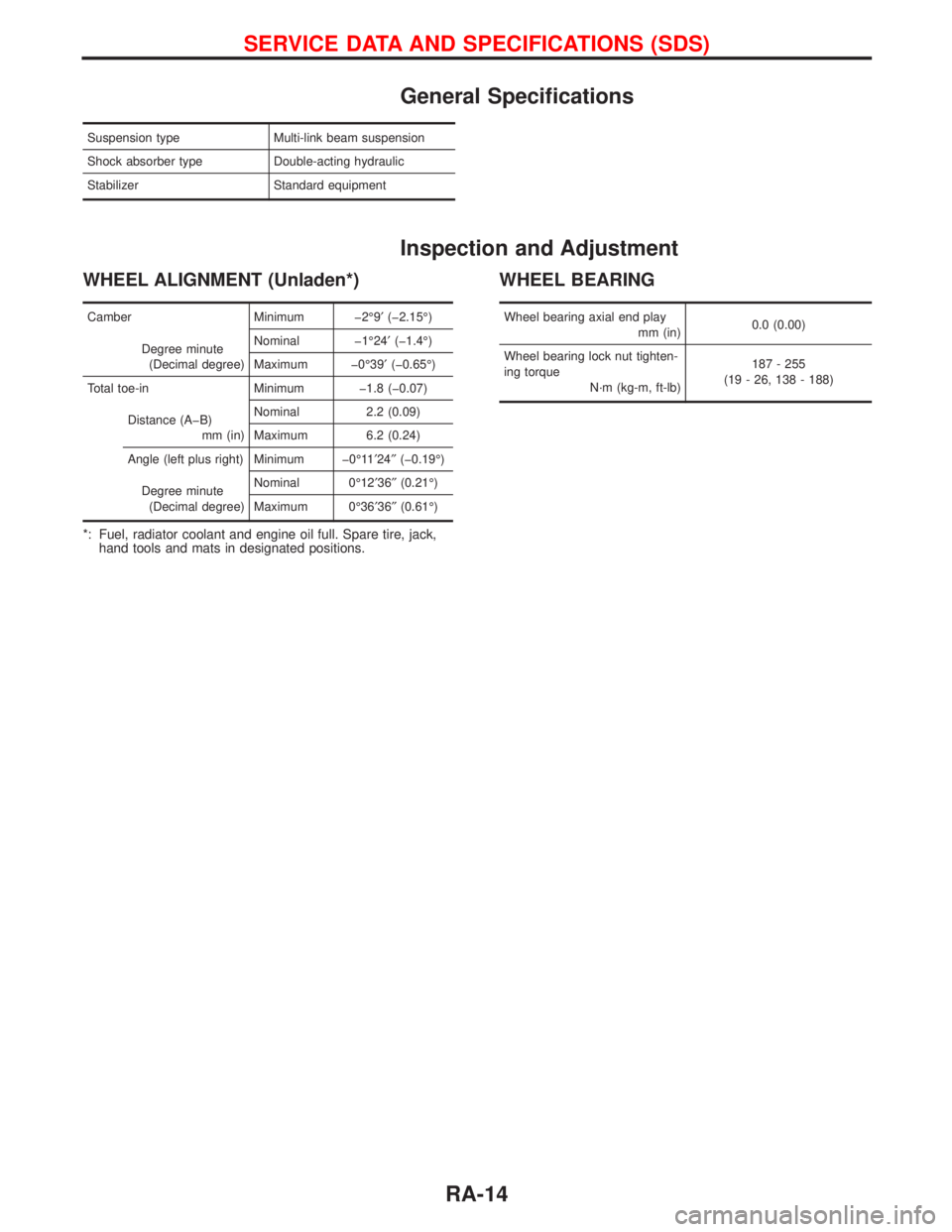
General Specifications
Suspension type Multi-link beam suspension
Shock absorber type Double-acting hydraulic
Stabilizer Standard equipment
Inspection and Adjustment
WHEEL ALIGNMENT (Unladen*)
Camber Minimum þ2É9¢(þ2.15É)
Degree minute
(Decimal degree)Nominal þ1É24¢(þ1.4É)
Maximum þ0É39¢(þ0.65É)
Total toe-in Minimum þ1.8 (þ0.07)
Distance (AþB)
mm (in)Nominal 2.2 (0.09)
Maximum 6.2 (0.24)
Angle (left plus right) Minimum þ0É11¢24²(þ0.19É)
Degree minute
(Decimal degree)Nominal 0É12¢36²(0.21É)
Maximum 0É36¢36²(0.61É)
*: Fuel, radiator coolant and engine oil full. Spare tire, jack,
hand tools and mats in designated positions.
WHEEL BEARING
Wheel bearing axial end play
mm (in)0.0 (0.00)
Wheel bearing lock nut tighten-
ing torque
N´m (kg-m, ft-lb)187 - 255
(19 - 26, 138 - 188)
SERVICE DATA AND SPECIFICATIONS (SDS)
RA-14
Page 2184 of 2267
RESTRAINT SYSTEM
SECTION
RS
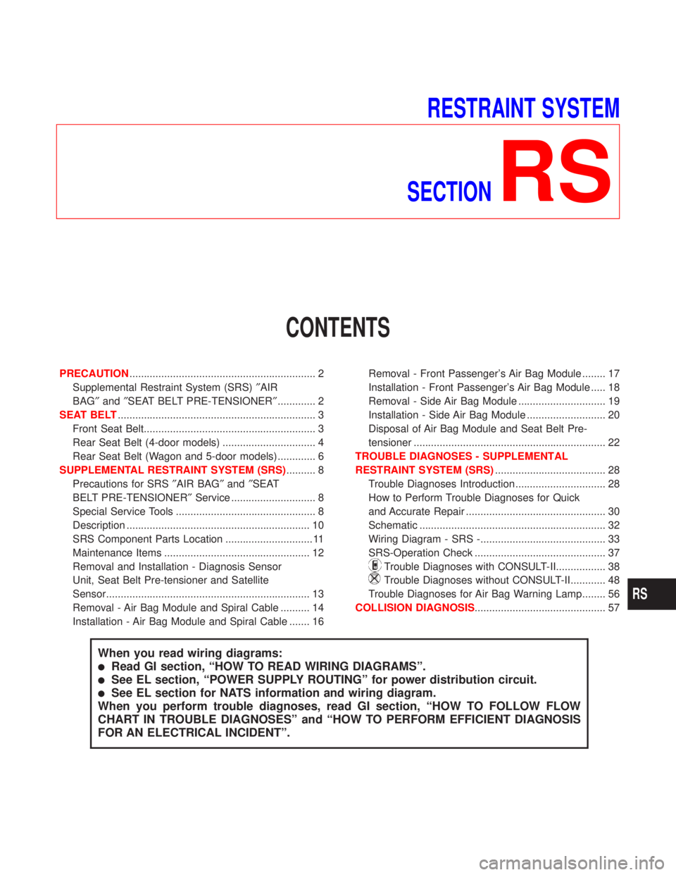
CONTENTS
PRECAUTION................................................................ 2
Supplemental Restraint System (SRS)²AIR
BAG²and²SEAT BELT PRE-TENSIONER²............. 2
SEAT BELT.................................................................... 3
Front Seat Belt........................................................... 3
Rear Seat Belt (4-door models) ................................ 4
Rear Seat Belt (Wagon and 5-door models)............. 6
SUPPLEMENTAL RESTRAINT SYSTEM (SRS).......... 8
Precautions for SRS²AIR BAG²and²SEAT
BELT PRE-TENSIONER²Service ............................. 8
Special Service Tools ................................................ 8
Description ............................................................... 10
SRS Component Parts Location .............................. 11
Maintenance Items .................................................. 12
Removal and Installation - Diagnosis Sensor
Unit, Seat Belt Pre-tensioner and Satellite
Sensor...................................................................... 13
Removal - Air Bag Module and Spiral Cable .......... 14
Installation - Air Bag Module and Spiral Cable ....... 16Removal - Front Passenger's Air Bag Module ........ 17
Installation - Front Passenger's Air Bag Module ..... 18
Removal - Side Air Bag Module .............................. 19
Installation - Side Air Bag Module ........................... 20
Disposal of Air Bag Module and Seat Belt Pre-
tensioner .................................................................. 22
TROUBLE DIAGNOSES - SUPPLEMENTAL
RESTRAINT SYSTEM (SRS)...................................... 28
Trouble Diagnoses Introduction............................... 28
How to Perform Trouble Diagnoses for Quick
and Accurate Repair ................................................ 30
Schematic ................................................................ 32
Wiring Diagram - SRS -........................................... 33
SRS-Operation Check ............................................. 37
Trouble Diagnoses with CONSULT-II................. 38
Trouble Diagnoses without CONSULT-II............ 48
Trouble Diagnoses for Air Bag Warning Lamp........ 56
COLLISION DIAGNOSIS............................................. 57
When you read wiring diagrams:
lRead GI section, ªHOW TO READ WIRING DIAGRAMSº.
lSee EL section, ªPOWER SUPPLY ROUTINGº for power distribution circuit.
lSee EL section for NATS information and wiring diagram.
When you perform trouble diagnoses, read GI section, ªHOW TO FOLLOW FLOW
CHART IN TROUBLE DIAGNOSESº and ªHOW TO PERFORM EFFICIENT DIAGNOSIS
FOR AN ELECTRICAL INCIDENTº.
RS
Page 2185 of 2267
Supplemental Restraint System (SRS) ªAIR
BAGº and ªSEAT BELT PRE-TENSIONERº
The Supplemental Restraint System such as ªAIR BAGº and ªSEAT BELT PRE-TENSIONERº used along
with a seat belt, help to reduce the risk or severity of injury to the driver and front passenger in certain types
of collision. The SRS system composition which is available to NISSAN MODEL P11 is as follows (The
composition varies according to the destination and optional equipment):
lFor a frontal collision
The Supplemental Restraint System consists of driver's air bag module (located in the center of the
steering wheel), front passenger's air bag module (located on the instrument panel on passenger's side),
seat belt pre-tensioners, a diagnosis sensor unit, warning lamp, wiring harness and spiral cable.
lFor a side collision
The Supplemental Restraint System consists of air bag modules (located in the outer side of front seats),
satellite sensor, diagnosis sensor unit (one of components of supplemental air bags for a frontal collision),
wiring harness, warning lamp (one of components of supplemental air bags for a frontal collision).
WARNING:
lTo avoid rendering the SRS inoperative, which could increase the risk of personal injury or death
in the event of a collision which would result in air bag inflation, all maintenance must be per-
formed by an authorized NISSAN dealer.
lImproper maintenance, including incorrect removal and installation of the SRS, can lead to per-
sonal injury caused by unintentional activation of the system.
lDo not use electrical test equipment on any circuit related to the SRS unless instructed to in this
Service Manual. Spiral cable and SRS wiring harnesses except ªSEAT BELT PRE-TENSIONERº
connectors can be identified by yellow harness connector (and with yellow harness protector or
yellow insulation tape before the harness connectors).
CAUTION:
lBefore removing the seat belt pre-tensioner assembly, turn the ignition switch OFF, disconnect
both battery cables and wait at least 3 minutes.
lDo not use electrical test equipment for seat belt pre-tensioner connector.
lAfter replacing or installing seat belt pre-tensioner assembly, or reconnecting seat belt pre-ten-
sioner connector, check the system function. Refer to ªSRS Operation Checkº (RS-37) for details.
lDo not disassemble buckle or seat belt assembly.
lReplace anchor bolts if they are deformed or worn out.
lNever oil tongue and buckle.
lIf any component of seat belt assembly is questionable, do not repair. Replace the whole seat
belt assembly.
lIf webbing is cut, frayed, or damaged, replace seat belt assembly.
lWhen replacing seat belt assembly, use a genuine seat belt assembly.
lAfter any collision, inspect all seat belt assemblies, including retractors and other attached
hardwares (i.e., guide rail set).
PRECAUTION
RS-2
Page 2186 of 2267
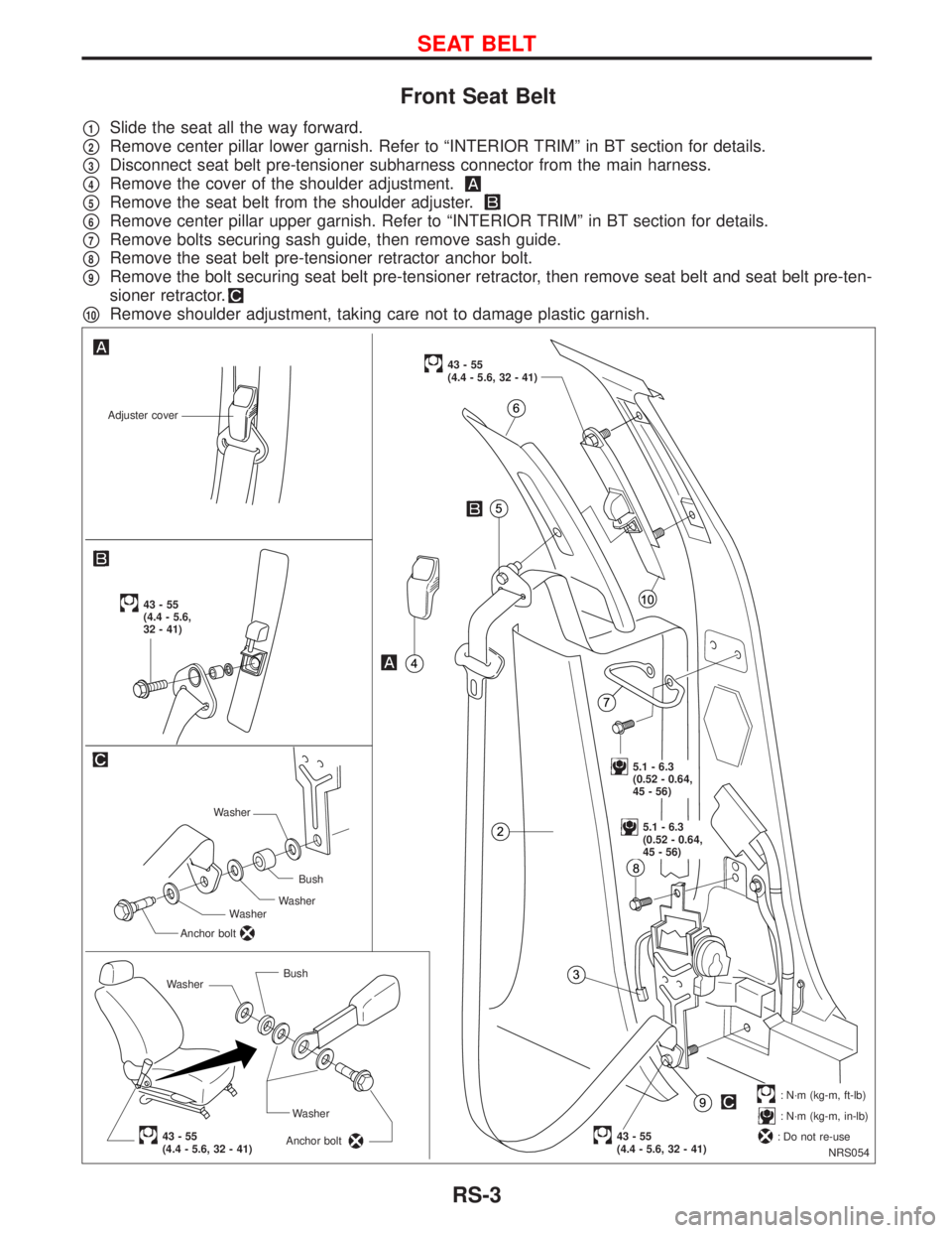
Front Seat Belt
p1Slide the seat all the way forward.
p2Remove center pillar lower garnish. Refer to ªINTERIOR TRIMº in BT section for details.
p3Disconnect seat belt pre-tensioner subharness connector from the main harness.
p4Remove the cover of the shoulder adjustment.
p5Remove the seat belt from the shoulder adjuster.
p6Remove center pillar upper garnish. Refer to ªINTERIOR TRIMº in BT section for details.
p7Remove bolts securing sash guide, then remove sash guide.
p8Remove the seat belt pre-tensioner retractor anchor bolt.
p9Remove the bolt securing seat belt pre-tensioner retractor, then remove seat belt and seat belt pre-ten-
sioner retractor.
p10Remove shoulder adjustment, taking care not to damage plastic garnish.
NRS054
Adjuster cover
WasherBush
Washer
Anchor bolt
43-55(4.4 - 5.6, 32 - 41)
43-55
(4.4 - 5.6, 32 - 41)
.5.1 - 6.3
(0.52 - 0.64,
45 - 56)
.5.1 - 6.3
(0.52 - 0.64,
45 - 56)
.43-55(4.4 - 5.6, 32 - 41)
43-55
(4.4 - 5.6,
32 - 41)
.: N´m (kg-m, ft-lb)
: N´m (kg-m, in-lb)
: Do not re-use WasherBush
Washer
Anchor bolt
Washer
SEAT BELT
RS-3
Page 2187 of 2267
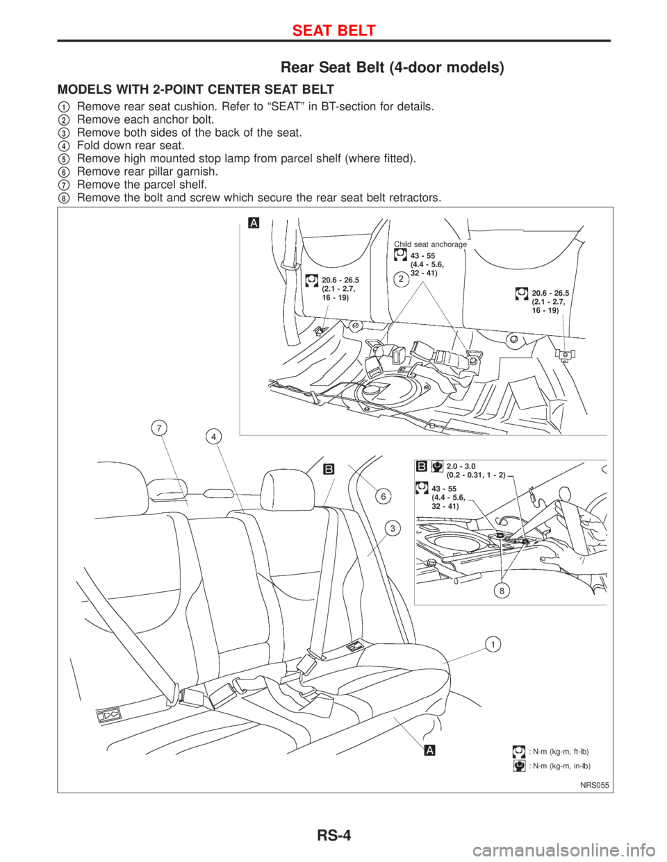
Rear Seat Belt (4-door models)
MODELS WITH 2-POINT CENTER SEAT BELT
p1Remove rear seat cushion. Refer to ªSEATº in BT-section for details.
p2Remove each anchor bolt.
p3Remove both sides of the back of the seat.
p4Fold down rear seat.
p5Remove high mounted stop lamp from parcel shelf (where fitted).
p6Remove rear pillar garnish.
p7Remove the parcel shelf.
p8Remove the bolt and screw which secure the rear seat belt retractors.
NRS055
2.0 - 3.0
(0.2 - 0.31,1-2)
43-55
(4.4 - 5.6,
32 - 41)
.: N´m (kg-m, ft-lb)
: N´m (kg-m, in-lb)
.Child seat anchorage
43-55
(4.4 - 5.6,
32 - 41)
20.6 - 26.5
(2.1 - 2.7,
16 - 19)
20.6 - 26.5
(2.1 - 2.7,
16 - 19)
SEAT BELT
RS-4
Page 2188 of 2267
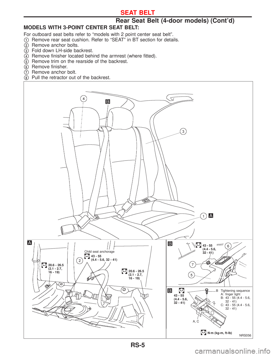
MODELS WITH 3-POINT CENTER SEAT BELT:
For outboard seat belts refer to ªmodels with 2 point center seat beltº.
p1Remove rear seat cushion. Refer to ªSEATº in BT section for details.
p2Remove anchor bolts.
p3Fold down LH-side backrest.
p4Remove finisher located behind the armrest (where fitted).
p5Remove trim on the rearside of the backrest.
p6Remove finisher.
p7Remove anchor bolt.
p8Pull the retractor out of the backrest.
NRS056
.Child seat anchorage
43-55
(4.4 - 5.6, 32 - 41)
.43-55
(4.4 - 5.6,
32 - 41)
43-55
(4.4 - 5.6,
32 - 41)
A, CB Tightening sequence
A: finger tight
B: 43 - 55 (4.4 - 5.6,
32 - 41)
C: 43 - 55 (4.4 - 5.6,
32 - 41)
N´m (kg-m, ft-lb)
20.6 - 26.5
(2.1 - 2.7,
16 - 19)
20.6 - 26.5
(2.1 - 2.7,
16 - 19)
SEAT BELT
Rear Seat Belt (4-door models) (Cont'd)
RS-5
Page 2189 of 2267
Rear Seat Belt (Wagon and 5-door models)
MODELS WITH 2-POINT CENTER SEAT BELT
p1Remove rear seat cushion. Refer to ªSEATº in BT-section for details.
p2Remove each anchor bolt.
p3Fold down rear seat back.
p4Remove rear seat back carpet and clips.
p5Remove seat belt retractor escutcheon.
p6Unclip rear seat back lock release button then remove the lock release escutcheon.
p7Remove fabric covering portion of the seat belt retractor.
p8Remove the seat belt retractor cover.
p9Loosen the seat belt retractor anchor bolt, then remove the seat belt retractor.
p10Remove interlock cable end from the seat belt retractor. (If necessary)
MODELS WITH 3-POINT CENTER SEAT BELT
The procedure is same as 2-point center seat belt models.
When removing 3-point center seatbelt, the procedure
p6should be skipped.
SEAT BELT
RS-6
Page 2190 of 2267
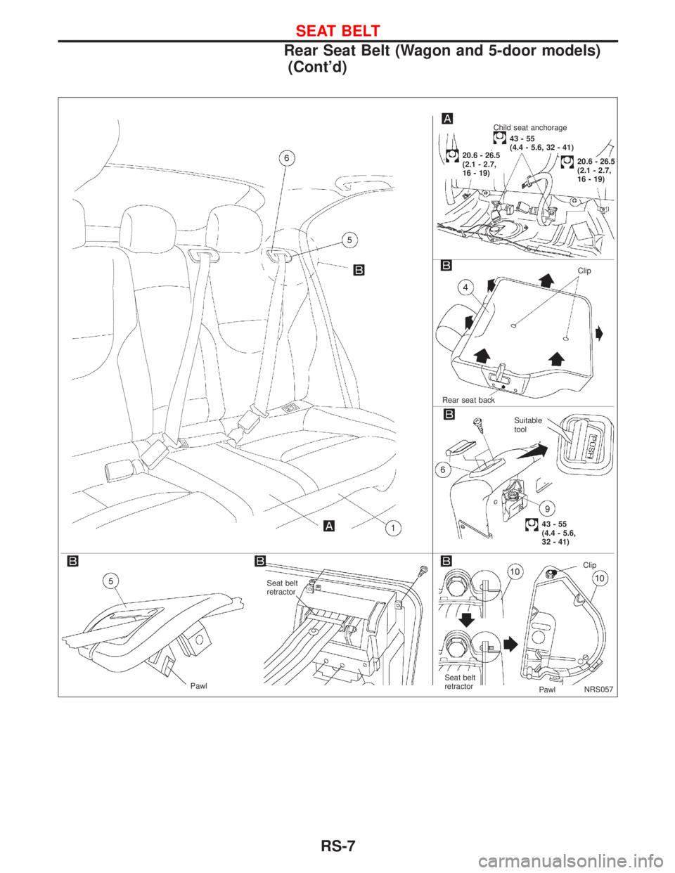
NRS057
.Child seat anchorage
43-55
(4.4 - 5.6, 32 - 41)
Clip
.Rear seat back
43-55
(4.4 - 5.6,
32 - 41) Suitable
tool
Seat belt
retractor
Clip
Seat belt
retractor
Pawl Pawl
.20.6 - 26.5
(2.1 - 2.7,
16 - 19)
.20.6 - 26.5
(2.1 - 2.7,
16 - 19)
SEAT BELT
Rear Seat Belt (Wagon and 5-door models)
(Cont'd)
RS-7