NISSAN TEANA 2008 Service Manual
Manufacturer: NISSAN, Model Year: 2008, Model line: TEANA, Model: NISSAN TEANA 2008Pages: 5121, PDF Size: 69.03 MB
Page 2971 of 5121
INL-92
< ON-VEHICLE REPAIR >
VANITY MIRROR LAMP
VANITY MIRROR LAMP
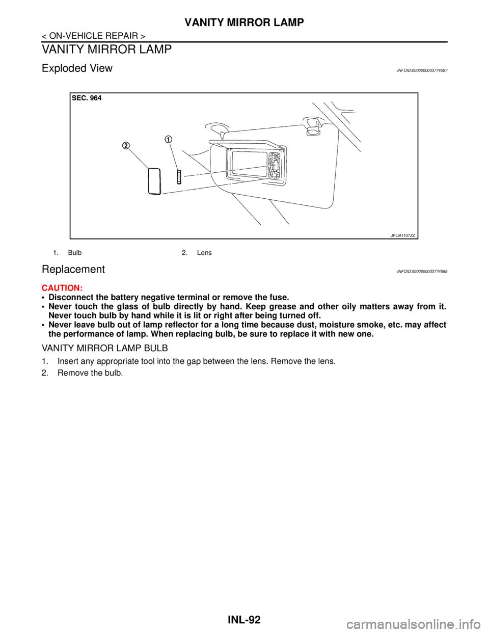
Exploded ViewINFOID:0000000003774587
ReplacementINFOID:0000000003774588
CAUTION:
Disconnect the battery negative terminal or remove the fuse.
Never touch the glass of bulb directly by hand. Keep grease and other oily matters away from it.
Never touch bulb by hand while it is lit or right after being turned off.
Never leave bulb out of lamp reflector for a long time because dust, moisture smoke, etc. may affect
the performance of lamp. When replacing bulb, be sure to replace it with new one.
VANITY MIRROR LAMP BULB
1. Insert any appropriate tool into the gap between the lens. Remove the lens.
2. Remove the bulb.
1. Bulb 2. Lens
JPLIA1107ZZ
Page 2972 of 5121
ASHTRAY ILLUMINATION
INL-93
< ON-VEHICLE REPAIR >
C
D
E
F
G
H
I
J
K
MA
B
INL
N
O
P
ASHTRAY ILLUMINATION
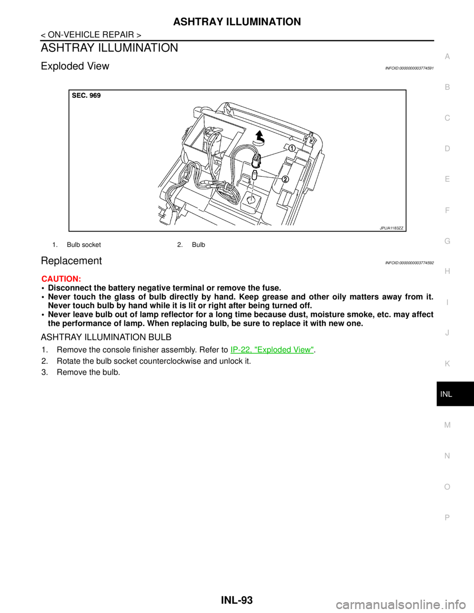
Exploded ViewINFOID:0000000003774591
ReplacementINFOID:0000000003774592
CAUTION:
Disconnect the battery negative terminal or remove the fuse.
Never touch the glass of bulb directly by hand. Keep grease and other oily matters away from it.
Never touch bulb by hand while it is lit or right after being turned off.
Never leave bulb out of lamp reflector for a long time because dust, moisture smoke, etc. may affect
the performance of lamp. When replacing bulb, be sure to replace it with new one.
ASHTRAY ILLUMINATION BULB
1. Remove the console finisher assembly. Refer to IP-22, "Exploded View".
2. Rotate the bulb socket counterclockwise and unlock it.
3. Remove the bulb.
1. Bulb socket 2. Bulb
JPLIA1183ZZ
Page 2973 of 5121
INL-94
< ON-VEHICLE REPAIR >
GLOVE BOX LAMP
GLOVE BOX LAMP
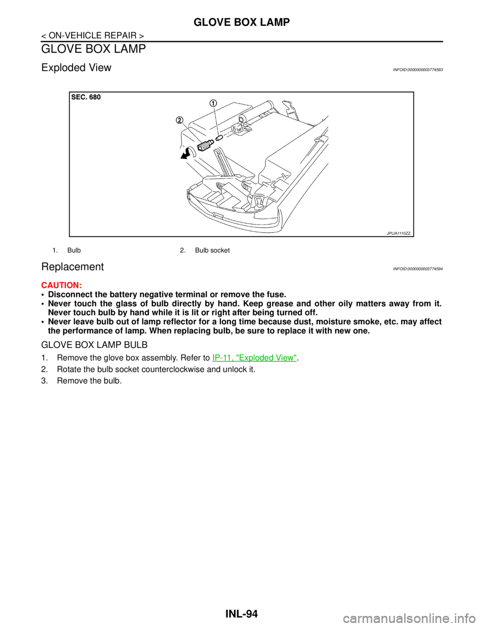
Exploded ViewINFOID:0000000003774593
ReplacementINFOID:0000000003774594
CAUTION:
Disconnect the battery negative terminal or remove the fuse.
Never touch the glass of bulb directly by hand. Keep grease and other oily matters away from it.
Never touch bulb by hand while it is lit or right after being turned off.
Never leave bulb out of lamp reflector for a long time because dust, moisture smoke, etc. may affect
the performance of lamp. When replacing bulb, be sure to replace it with new one.
GLOVE BOX LAMP BULB
1. Remove the glove box assembly. Refer to IP-11, "Exploded View".
2. Rotate the bulb socket counterclockwise and unlock it.
3. Remove the bulb.
1. Bulb 2. Bulb socket
J P L I A 111 0 Z Z
Page 2974 of 5121
STEP LAMP
INL-95
< ON-VEHICLE REPAIR >
C
D
E
F
G
H
I
J
K
MA
B
INL
N
O
P
STEP LAMP
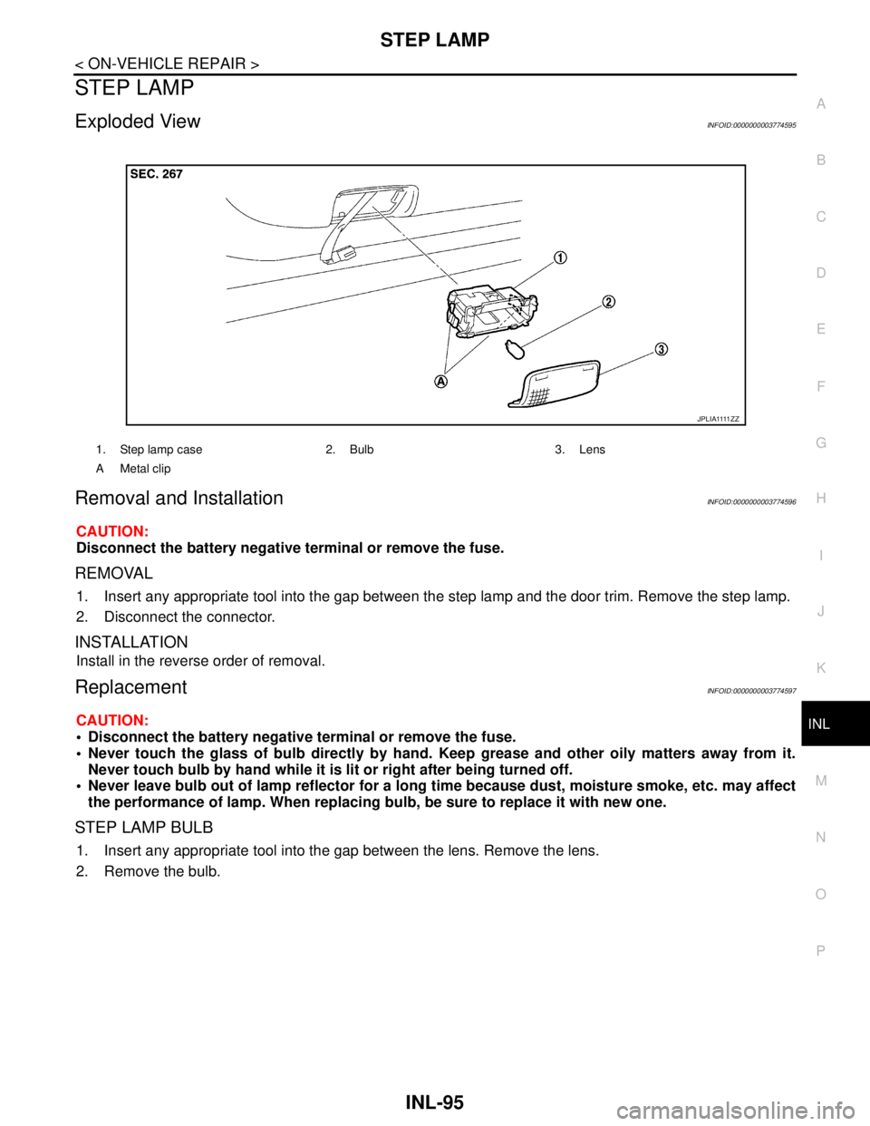
Exploded ViewINFOID:0000000003774595
Removal and InstallationINFOID:0000000003774596
CAUTION:
Disconnect the battery negative terminal or remove the fuse.
REMOVAL
1. Insert any appropriate tool into the gap between the step lamp and the door trim. Remove the step lamp.
2. Disconnect the connector.
INSTALLATION
Install in the reverse order of removal.
ReplacementINFOID:0000000003774597
CAUTION:
Disconnect the battery negative terminal or remove the fuse.
Never touch the glass of bulb directly by hand. Keep grease and other oily matters away from it.
Never touch bulb by hand while it is lit or right after being turned off.
Never leave bulb out of lamp reflector for a long time because dust, moisture smoke, etc. may affect
the performance of lamp. When replacing bulb, be sure to replace it with new one.
STEP LAMP BULB
1. Insert any appropriate tool into the gap between the lens. Remove the lens.
2. Remove the bulb.
1. Step lamp case 2. Bulb 3. Lens
A Metal clip
J P L I A 1111 Z Z
Page 2975 of 5121
INL-96
< ON-VEHICLE REPAIR >
PERSONAL LAMP
PERSONAL LAMP
Exploded ViewINFOID:0000000003774598
NOTE:
After removing the headlining assembly, remove the personal lamp assembly. Refer to INT-49, "
NORMAL
ROOF : Exploded View".
Replace the personal lamp assembly as a set (right and left).
Removal and InstallationINFOID:0000000003774599
After removing the headlining assembly, remove the personal lamp assembly. Refer to INT-49, "NORMAL
ROOF : Exploded View".
Replace the personal lamp assembly as a set (right and left).
ReplacementINFOID:0000000003774600
CAUTION:
Disconnect the battery negative terminal or remove the fuse.
Never touch the glass of bulb directly by hand. Keep grease and other oily matters away from it.
Never touch bulb by hand while it is lit or right after being turned off.
Never leave bulb out of lamp reflector for a long time because dust, moisture smoke, etc. may affect
the performance of lamp. When replacing bulb, be sure to replace it with new one.
PERSONAL LAMP BULB
1. Insert any appropriate tool into the gap between the lens. Remove the lens.
2. Remove the bulb.
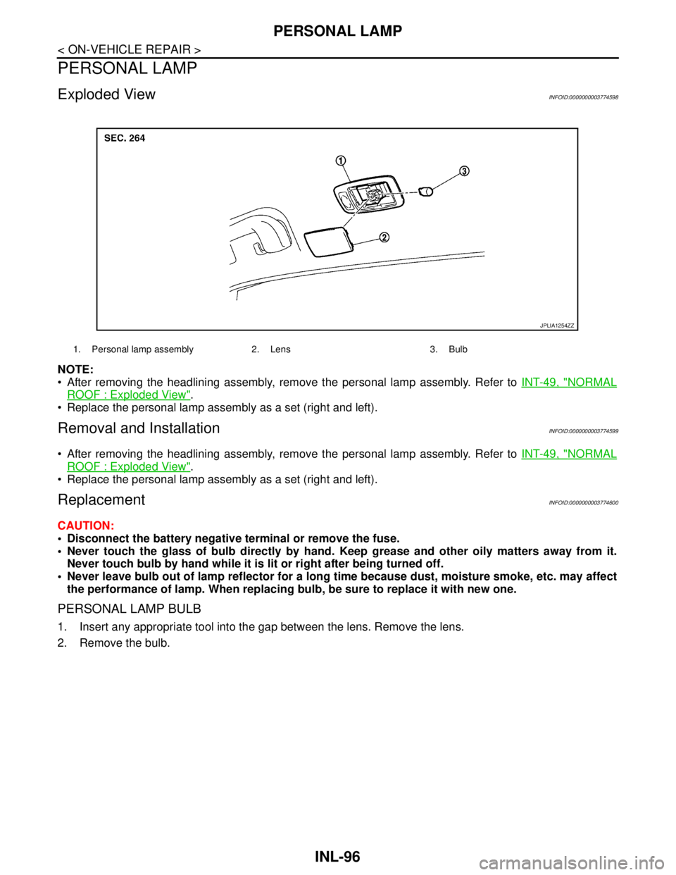
1. Personal lamp assembly 2. Lens 3. Bulb
JPLIA1254ZZ
Page 2976 of 5121
TRUNK ROOM LAMP
INL-97
< ON-VEHICLE REPAIR >
C
D
E
F
G
H
I
J
K
MA
B
INL
N
O
P
TRUNK ROOM LAMP
Exploded ViewINFOID:0000000003812235
Removal and InstallationINFOID:0000000003812236
CAUTION:
Disconnect the battery negative terminal or remove the fuse.
REMOVAL
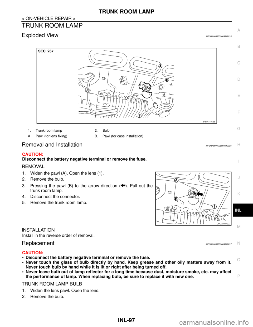
1. Widen the pawl (A). Open the lens (1).
2. Remove the bulb.
3. Pressing the pawl (B) to the arrow direction ( ). Pull out the
trunk room lamp.
4. Disconnect the connector.
5. Remove the trunk room lamp.
INSTALLATION
Install in the reverse order of removal.
ReplacementINFOID:0000000003812237
CAUTION:
Disconnect the battery negative terminal or remove the fuse.
Never touch the glass of bulb directly by hand. Keep grease and other oily matters away from it.
Never touch bulb by hand while it is lit or right after being turned off.
Never leave bulb out of lamp reflector for a long time because dust, moisture smoke, etc. may affect
the performance of lamp. When replacing bulb, be sure to replace it with new one.
TRUNK ROOM LAMP BULB
1. Widen the lens pawl. Open the lens.
2. Remove the bulb.
1. Trunk room lamp 2. Bulb
A Pawl (for lens fixing) B. Pawl (for case installation)
J P L I A 111 6 Z Z
J P L I A 111 7 Z Z
Page 2977 of 5121
INL-98
< SERVICE DATA AND SPECIFICATIONS (SDS)
SERVICE DATA AND SPECIFICATIONS (SDS)
SERVICE DATA AND SPECIFICATIONS (SDS)
SERVICE DATA AND SPECIFICATIONS (SDS)
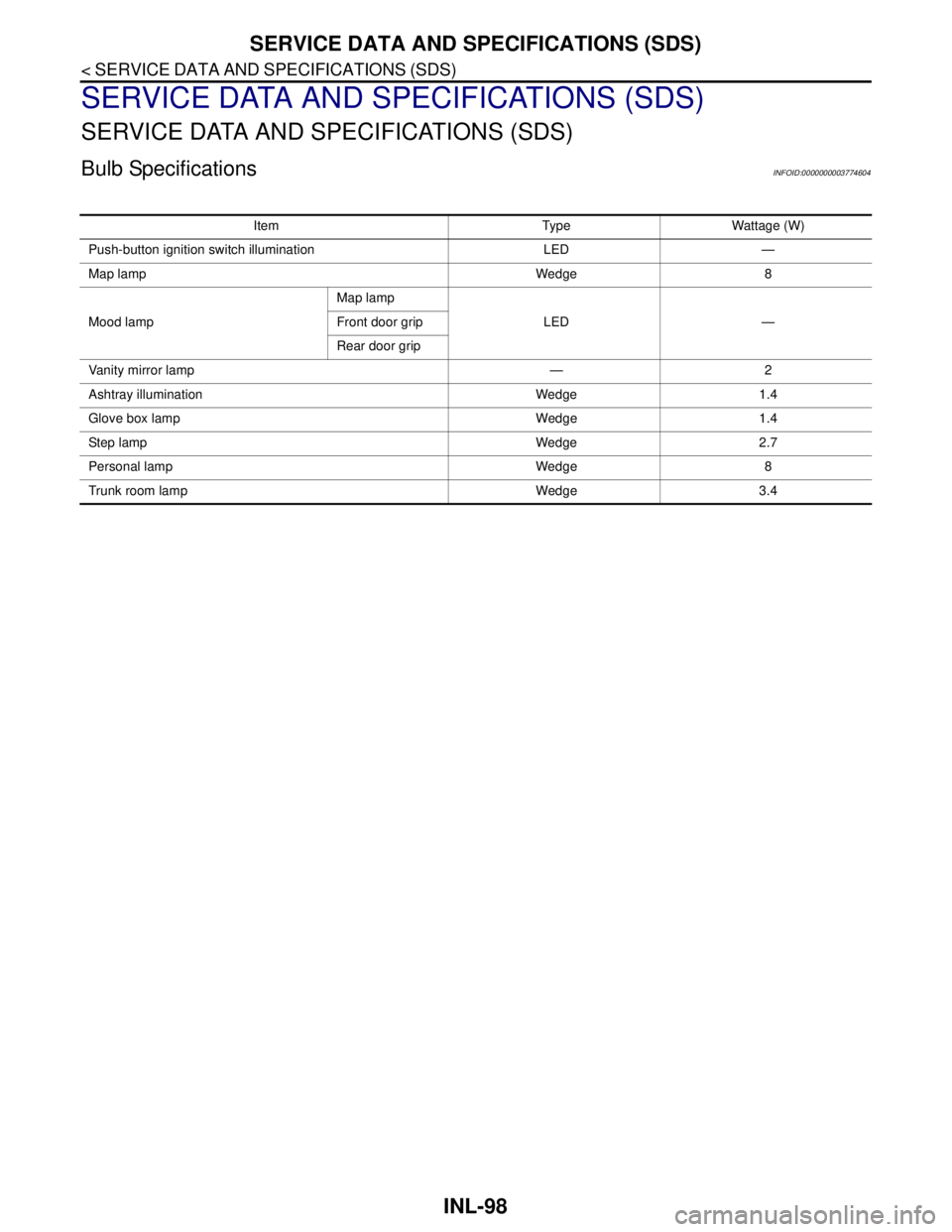
Bulb SpecificationsINFOID:0000000003774604
Item Type Wattage (W)
Push-button ignition switch illumination LED —
Map lamp Wedge 8
Mood lampMap lamp
LED — Front door grip
Rear door grip
Vanity mirror lamp — 2
Ashtray illumination Wedge 1.4
Glove box lamp Wedge 1.4
Ste p l am p We dg e 2. 7
Personal lamp Wedge 8
Trunk room lamp Wedge 3.4
Page 2978 of 5121
INT-1
BODY INTERIOR
C
D
E
F
G
H
I
K
L
M
SECTION INT
A
B
INT
N
O
P
CONTENTS
INTERIOR
BASIC INSPECTION ....................................3
DIAGNOSIS AND REPAIR WORKFLOW ..........3
WorkFlow ..................................................................3
FUNCTION DIAGNOSIS ...............................4
REAR SUNSHADE SYSTEM ..............................4
System Diagram ........................................................4
System Description ...................................................4
Component Parts Location ........................................4
Component Description .............................................5
COMPONENT DIAGNOSIS ..........................6
POWER SUPPLY AND GROUND CIRCUIT .......6
REAR SUNSHADE CONTROL UNIT ..........................6
REAR SUNSHADE CONTROL UNIT : Diagnosis
Procedure ..................................................................
6
REAR SUNSHADE SWITCH ..............................7
FRONT .........................................................................7
FRONT : Description .................................................7
FRONT : Component Function Check ......................7
FRONT : Diagnosis Procedure .................................7
FRONT : Component Inspection ...............................8
REAR ...........................................................................8
REAR : Description ...................................................8
REAR : Component Function Check .........................8
REAR : Diagnosis Procedure ....................................8
REAR : Component Inspection ...............................10
REAR SUNSHADE MOTOR ..............................11
Description ..............................................................11
Component Function Check ....................................11
Diagnosis Procedure ...............................................11
REVERSE SIGNAL CIRCUIT .............................12
Description ..............................................................12
Component Function Check ....................................12
Diagnosis Procedure ...............................................12
ECU DIAGNOSIS .........................................13
REAR SUNSHADE CONTROL UNIT ...............13
Reference Value ......................................................13
Wiring Diagram - REAR SUNSHADE CONTROL
SYSTEM - ................................................................
14
SYMPTOM DIAGNOSIS ..............................18
REAR SUNSHADE DOES NOT OPERATE .....18
WHEN TURNING ON REAR SUNSHADE SWITCH
(FRONT AND REAR) .................................................
18
WHEN TURNING ON REAR SUNSHADE
SWITCH (FRONT AND REAR) : Diagnosis Proce-
dure .........................................................................
18
WHEN TURNING ON REAR SUNSHADE SWITCH
(FRONT) .....................................................................
18
WHEN TURNING ON REAR SUNSHADE
SWITCH (FRONT) : Diagnosis Procedure ..............
18
WHEN TURNING ON REAR SUNSHADE SWITCH
(REAR) .......................................................................
18
WHEN TURNING ON REAR SUNSHADE
SWITCH (REAR) : Diagnosis Procedure .................
18
REAR SUNSHADE DOES NOT LOWER
WHEN SHIFT LEVER IS IN THE "R" POSI-
TION ..................................................................
20
Diagnosis Procedure ...............................................20
SQUEAK AND RATTLE TROUBLE DIAG-
NOSES ..............................................................
21
Work Flow ................................................................21
Inspection Procedure ...............................................23
Diagnostic Worksheet ..............................................25
PRECAUTION ..............................................27
PRECAUTIONS .................................................27
Page 2979 of 5121

INT-2
Precaution for Supplemental Restraint System
(SRS) "AIR BAG" and "SEAT BELT PRE-TEN-
SIONER" .................................................................
27
Precaution Necessary for Steering Wheel Rota-
tion after Battery Disconnect ..................................
27
Precaution for Procedure without Cowl Top Cover ...28
Precaution for Work ................................................28
PREPARATION ...........................................29
PREPARATION .................................................29
Commercial Service Tools ......................................29
ON-VEHICLE REPAIR ................................30
FRONT DOOR FINISHER .................................30
DRIVER SIDE ............................................................30
DRIVER SIDE : Exploded View ..............................30
DRIVER SIDE : Removal and Installation ..............30
PASSENGER SIDE ...................................................32
PASSENGER SIDE : Exploded View .....................33
PASSENGER SIDE : Removal and Installation .....33
REAR DOOR FINISHER ....................................36
Exploded View ........................................................36
Removal and Installation ........................................36
BODY SIDE TRIM ..............................................39
Exploded View ........................................................39
Removal and Installation ........................................39
REAR PARCEL SHELF FINISHER ...................43
Exploded View ........................................................43
Removal and Installation ........................................43
REAR SUNSHADE ............................................45
Exploded View ........................................................45
Removal and Installation .........................................45
FLOOR TRIM .....................................................47
Exploded View ........................................................47
Removal and Installation .........................................47
HEADLINING .....................................................49
NORMAL ROOF ........................................................49
NORMAL ROOF : Exploded View ..........................49
NORMAL ROOF : Removal and Installation ...........50
SUNROOF .................................................................52
SUNROOF : Exploded View ...................................53
SUNROOF : Removal and Installation ....................54
TRUNK ROOM TRIM .........................................57
Exploded View ........................................................57
Removal and Installation .........................................57
TRUNK LID TRIM ..............................................59
Exploded View ........................................................59
Removal and Installation .........................................59
REAR SUNSHADE CONTROL UNIT ................61
Exploded View ........................................................61
Removal and Installation .........................................61
REAR SUNSHADE SWITCH .............................62
FRONT .......................................................................62
FRONT : Exploded View .........................................62
FRONT : Removal and Installation .........................62
REAR .........................................................................62
REAR : Exploded View ...........................................63
REAR : Removal and Installation ............................63
Page 2980 of 5121
DIAGNOSIS AND REPAIR WORKFLOW
INT-3
< BASIC INSPECTION >
C
D
E
F
G
H
I
K
L
MA
B
INT
N
O
P
BASIC INSPECTION
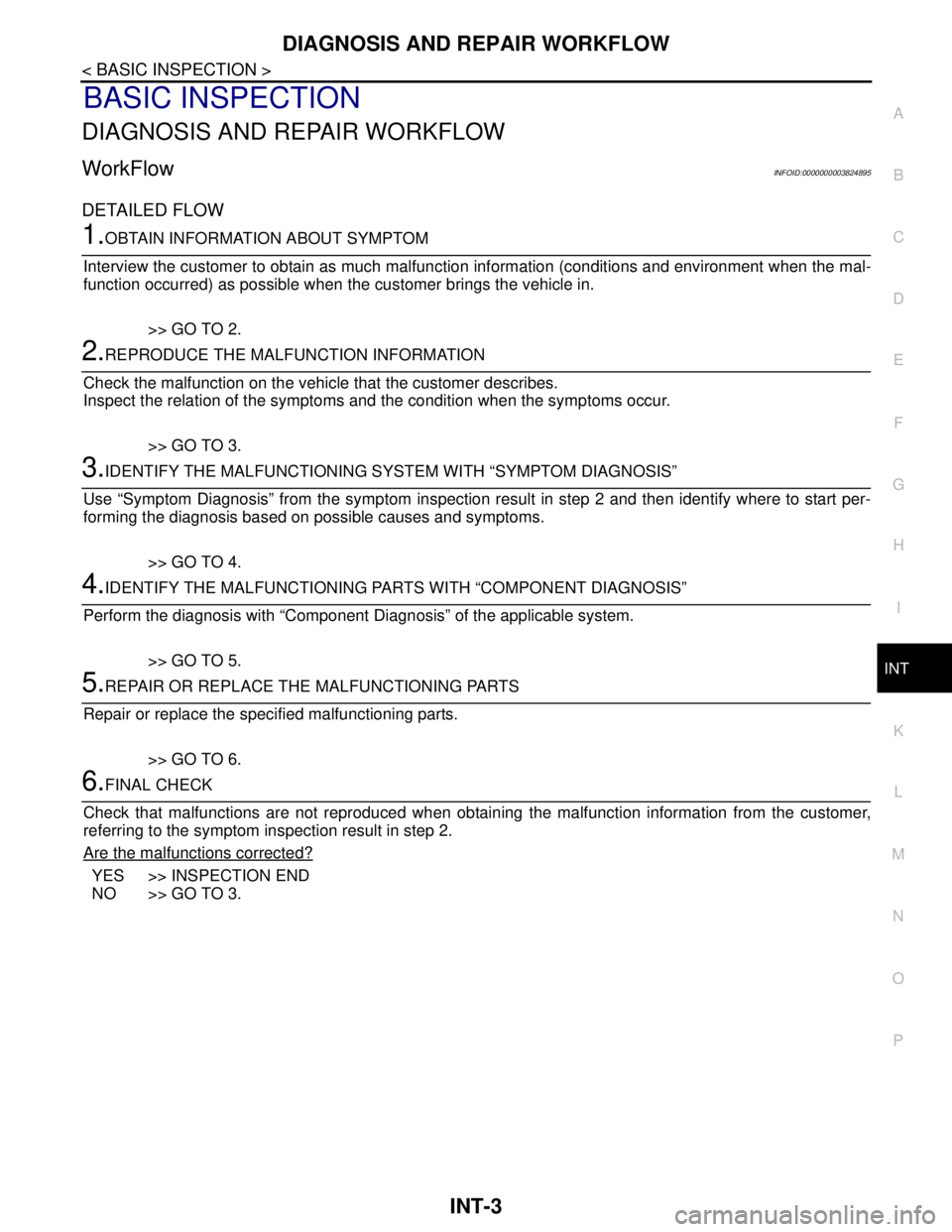
DIAGNOSIS AND REPAIR WORKFLOW
WorkFlowINFOID:0000000003824895
DETAILED FLOW
1.OBTAIN INFORMATION ABOUT SYMPTOM
Interview the customer to obtain as much malfunction information (conditions and environment when the mal-
function occurred) as possible when the customer brings the vehicle in.
>> GO TO 2.
2.REPRODUCE THE MALFUNCTION INFORMATION
Check the malfunction on the vehicle that the customer describes.
Inspect the relation of the symptoms and the condition when the symptoms occur.
>> GO TO 3.
3.IDENTIFY THE MALFUNCTIONING SYSTEM WITH “SYMPTOM DIAGNOSIS”
Use “Symptom Diagnosis” from the symptom inspection result in step 2 and then identify where to start per-
forming the diagnosis based on possible causes and symptoms.
>> GO TO 4.
4.IDENTIFY THE MALFUNCTIONING PARTS WITH “COMPONENT DIAGNOSIS”
Perform the diagnosis with “Component Diagnosis” of the applicable system.
>> GO TO 5.
5.REPAIR OR REPLACE THE MALFUNCTIONING PARTS
Repair or replace the specified malfunctioning parts.
>> GO TO 6.
6.FINAL CHECK
Check that malfunctions are not reproduced when obtaining the malfunction information from the customer,
referring to the symptom inspection result in step 2.
Are the malfunctions corrected?
YES >> INSPECTION END
NO >> GO TO 3.