NISSAN TERRANO 2002 Service Repair Manual
Manufacturer: NISSAN, Model Year: 2002, Model line: TERRANO, Model: NISSAN TERRANO 2002Pages: 1767, PDF Size: 41.51 MB
Page 211 of 1767
Removal
CAUTION:
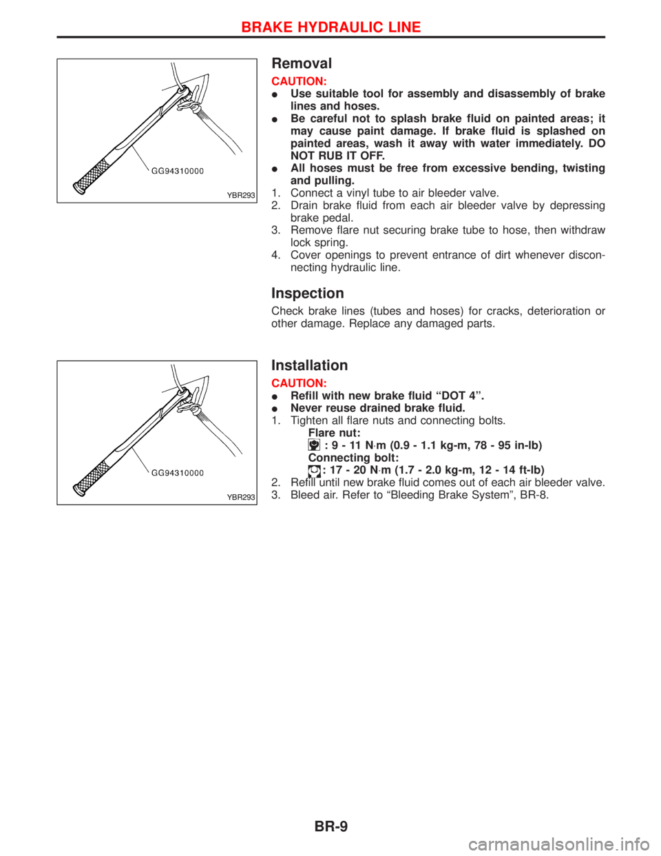
IUse suitable tool for assembly and disassembly of brake
lines and hoses.
IBe careful not to splash brake fluid on painted areas; it
may cause paint damage. If brake fluid is splashed on
painted areas, wash it away with water immediately. DO
NOT RUB IT OFF.
IAll hoses must be free from excessive bending, twisting
and pulling.
1. Connect a vinyl tube to air bleeder valve.
2. Drain brake fluid from each air bleeder valve by depressing
brake pedal.
3. Remove flare nut securing brake tube to hose, then withdraw
lock spring.
4. Cover openings to prevent entrance of dirt whenever discon-
necting hydraulic line.
Inspection
Check brake lines (tubes and hoses) for cracks, deterioration or
other damage. Replace any damaged parts.
Installation
CAUTION:
IRefill with new brake fluid ªDOT 4º.
INever reuse drained brake fluid.
1. Tighten all flare nuts and connecting bolts.
Flare nut:
:9-11N×m (0.9 - 1.1 kg-m, 78 - 95 in-lb)
Connecting bolt:
:17-20N×m (1.7 - 2.0 kg-m, 12 - 14 ft-lb)
2. Refill until new brake fluid comes out of each air bleeder valve.
3. Bleed air. Refer to ªBleeding Brake Systemº, BR-8.
YBR293
YBR293
BRAKE HYDRAULIC LINE
BR-9
Page 212 of 1767
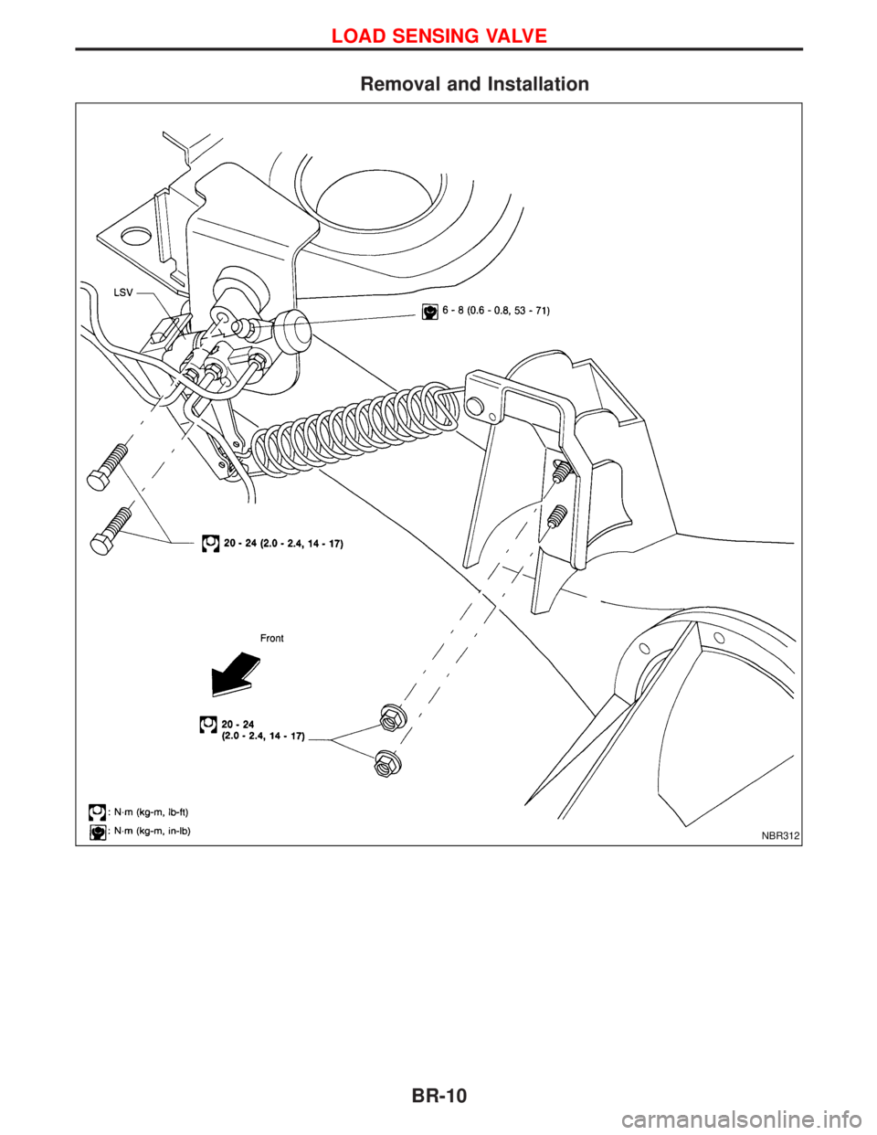
Removal and Installation
NBR312
LOAD SENSING VALVE
BR-10
Page 213 of 1767
Removal
CAUTION:
IBe careful not to splash brake fluid on painted areas; it
may cause paint damage. If brake fluid is splashed on
painted areas, wash it away with water immediately. DO
NOT RUB IT OFF.
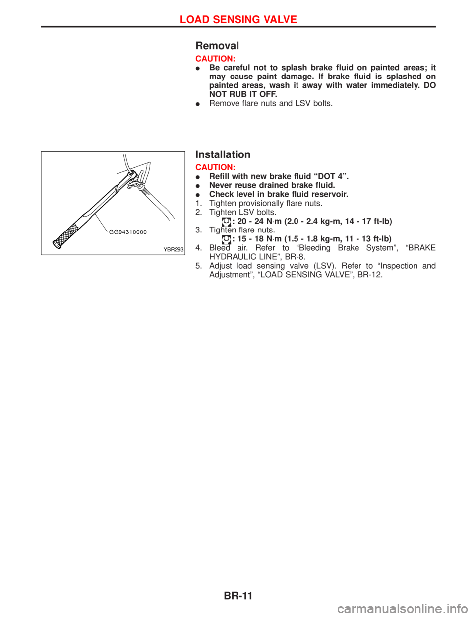
IRemove flare nuts and LSV bolts.
Installation
CAUTION:
IRefill with new brake fluid ªDOT 4º.
INever reuse drained brake fluid.
ICheck level in brake fluid reservoir.
1. Tighten provisionally flare nuts.
2. Tighten LSV bolts.
:20-24N×m (2.0 - 2.4 kg-m, 14 - 17 ft-lb)
3. Tighten flare nuts.
:15-18N×m (1.5 - 1.8 kg-m, 11 - 13 ft-lb)
4. Bleed air. Refer to ªBleeding Brake Systemº, ªBRAKE
HYDRAULIC LINEº, BR-8.
5. Adjust load sensing valve (LSV). Refer to ªInspection and
Adjustmentº, ªLOAD SENSING VALVEº, BR-12.
YBR293
LOAD SENSING VALVE
BR-11
Page 214 of 1767
Inspection and Adjustment
CAUTION:
ICheck level in brake fluid reservoir.
IRefill with recommended brake fluid ªDOT 4º.
INever reuse drained brake fluid.
IBe careful not to splash brake fluid on painted areas; it
may cause paint damage. If brake fluid is splashed on
painted areas wash it away with water immediately. DO
NOT RUB IT OFF.
1. Before adjusting load sensing valve spring length, check for
proper installation and abnormal wear of brake pads and
shoes.
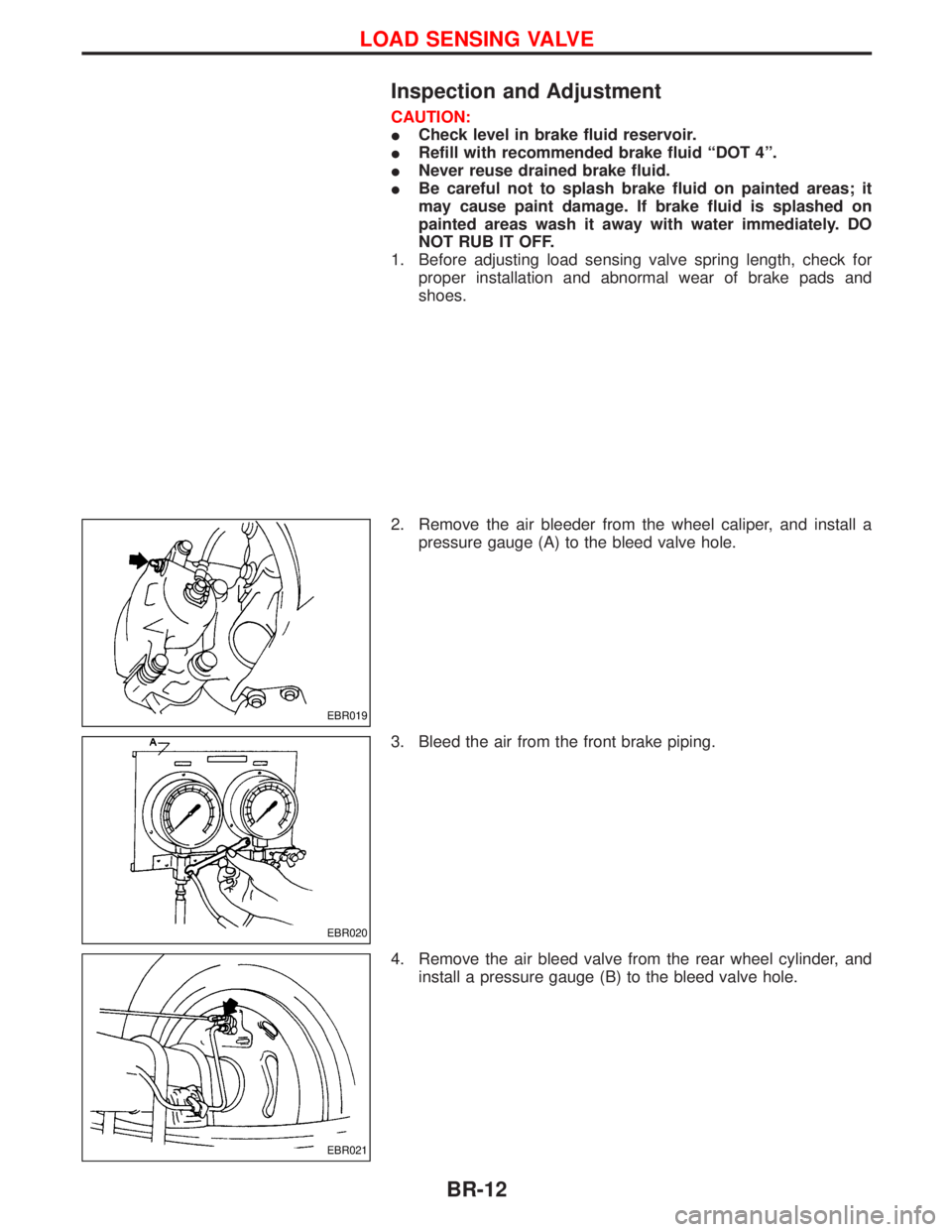
2. Remove the air bleeder from the wheel caliper, and install a
pressure gauge (A) to the bleed valve hole.
3. Bleed the air from the front brake piping.
4. Remove the air bleed valve from the rear wheel cylinder, and
install a pressure gauge (B) to the bleed valve hole.
EBR019
EBR020
EBR021
LOAD SENSING VALVE
BR-12
Page 215 of 1767
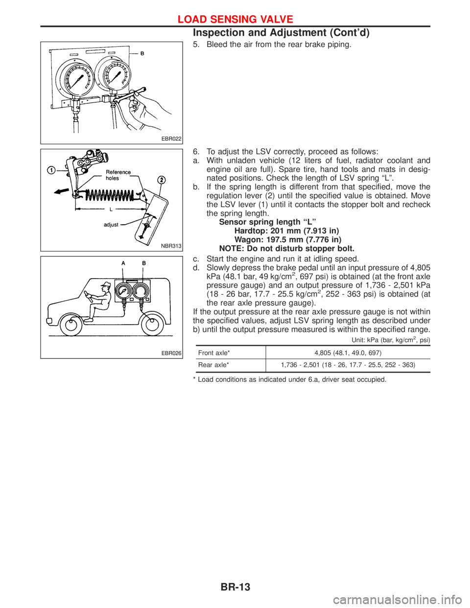
5. Bleed the air from the rear brake piping.
6. To adjust the LSV correctly, proceed as follows:
a. With unladen vehicle (12 liters of fuel, radiator coolant and
engine oil are full). Spare tire, hand tools and mats in desig-
nated positions. Check the length of LSV spring ªLº.
b. If the spring length is different from that specified, move the
regulation lever (2) until the specified value is obtained. Move
the LSV lever (1) until it contacts the stopper bolt and recheck
the spring length.
Sensor spring length ªLº
Hardtop: 201 mm (7.913 in)
Wagon: 197.5 mm (7.776 in)
NOTE: Do not disturb stopper bolt.
c. Start the engine and run it at idling speed.
d. Slowly depress the brake pedal until an input pressure of 4,805
kPa (48.1 bar, 49 kg/cm
2, 697 psi) is obtained (at the front axle
pressure gauge) and an output pressure of 1,736 - 2,501 kPa
(18 - 26 bar, 17.7 - 25.5 kg/cm
2, 252 - 363 psi) is obtained (at
the rear axle pressure gauge).
If the output pressure at the rear axle pressure gauge is not within
the specified values, adjust LSV spring length as described under
b) until the output pressure measured is within the specified range.
Unit: kPa (bar, kg/cm2, psi)
Front axle* 4,805 (48.1, 49.0, 697)
Rear axle* 1,736 - 2,501 (18 - 26, 17.7 - 25.5, 252 - 363)
* Load conditions as indicated under 6.a, driver seat occupied.
EBR022
NBR313
EBR026
LOAD SENSING VALVE
Inspection and Adjustment (Cont'd)
BR-13
Page 216 of 1767

Removal and Installation
NBR269
BRAKE PEDAL AND BRACKET
BR-14
Page 217 of 1767
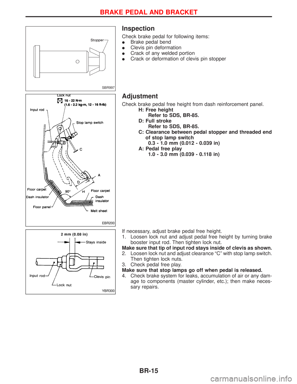
Inspection
Check brake pedal for following items:
IBrake pedal bend
IClevis pin deformation
ICrack of any welded portion
ICrack or deformation of clevis pin stopper
Adjustment
Check brake pedal free height from dash reinforcement panel.
H: Free height
Refer to SDS, BR-85.
D: Full stroke
Refer to SDS, BR-85.
C: Clearance between pedal stopper and threaded end
of stop lamp switch
0.3 - 1.0 mm (0.012 - 0.039 in)
A: Pedal free play
1.0 - 3.0 mm (0.039 - 0.118 in)
If necessary, adjust brake pedal free height.
1. Loosen lock nut and adjust pedal free height by turning brake
booster input rod. Then tighten lock nut.
Make sure that tip of input rod stays inside of clevis as shown.
2. Loosen lock nut and adjust clearance ªCº with stop lamp switch.
Then tighten lock nuts.
3. Check pedal free play.
Make sure that stop lamps go off when pedal is released.
4. Check brake system for leaks, accumulation of air or any dam-
age to components (master cylinder, etc.); then make neces-
sary repairs.
SBR997
EBR200
YBR300
BRAKE PEDAL AND BRACKET
BR-15
Page 218 of 1767
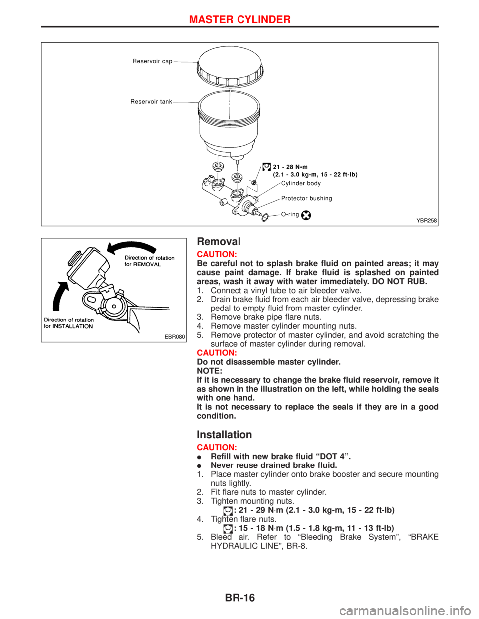
Removal
CAUTION:
Be careful not to splash brake fluid on painted areas; it may
cause paint damage. If brake fluid is splashed on painted
areas, wash it away with water immediately. DO NOT RUB.
1. Connect a vinyl tube to air bleeder valve.
2. Drain brake fluid from each air bleeder valve, depressing brake
pedal to empty fluid from master cylinder.
3. Remove brake pipe flare nuts.
4. Remove master cylinder mounting nuts.
5. Remove protector of master cylinder, and avoid scratching the
surface of master cylinder during removal.
CAUTION:
Do not disassemble master cylinder.
NOTE:
If it is necessary to change the brake fluid reservoir, remove it
as shown in the illustration on the left, while holding the seals
with one hand.
It is not necessary to replace the seals if they are in a good
condition.
Installation
CAUTION:
IRefill with new brake fluid ªDOT 4º.
INever reuse drained brake fluid.
1. Place master cylinder onto brake booster and secure mounting
nuts lightly.
2. Fit flare nuts to master cylinder.
3. Tighten mounting nuts.
:21-29N×m (2.1 - 3.0 kg-m, 15 - 22 ft-lb)
4. Tighten flare nuts.
:15-18N×m (1.5 - 1.8 kg-m, 11 - 13 ft-lb)
5. Bleed air. Refer to ªBleeding Brake Systemº, ªBRAKE
HYDRAULIC LINEº, BR-8.
YBR258
EBR080
MASTER CYLINDER
BR-16
Page 219 of 1767
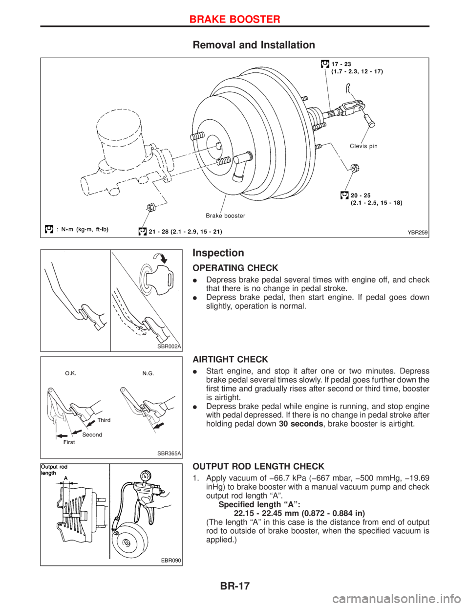
Removal and Installation
Inspection
OPERATING CHECK
IDepress brake pedal several times with engine off, and check
that there is no change in pedal stroke.
IDepress brake pedal, then start engine. If pedal goes down
slightly, operation is normal.
AIRTIGHT CHECK
IStart engine, and stop it after one or two minutes. Depress
brake pedal several times slowly. If pedal goes further down the
first time and gradually rises after second or third time, booster
is airtight.
IDepress brake pedal while engine is running, and stop engine
with pedal depressed. If there is no change in pedal stroke after
holding pedal down30 seconds, brake booster is airtight.
OUTPUT ROD LENGTH CHECK
1. Apply vacuum of þ66.7 kPa (þ667 mbar, þ500 mmHg, þ19.69
inHg) to brake booster with a manual vacuum pump and check
output rod length ªAº.
Specified length ªAº:
22.15 - 22.45 mm (0.872 - 0.884 in)
(The length ªAº in this case is the distance from end of output
rod to outside of brake booster, when the specified vacuum is
applied.)
YBR259
SBR002A
SBR365A
EBR090
BRAKE BOOSTER
BR-17
Page 220 of 1767
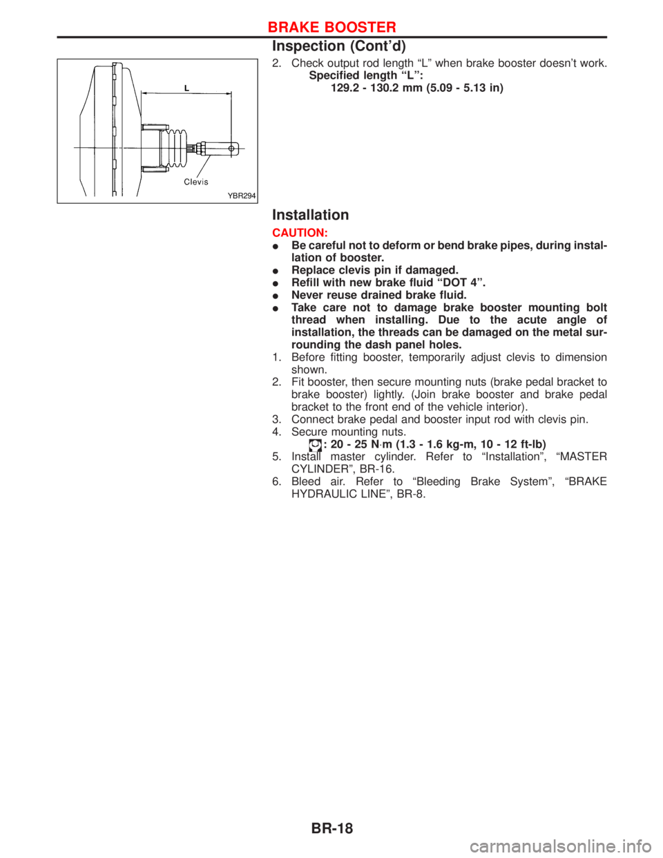
2. Check output rod length ªLº when brake booster doesn't work.
Specified length ªLº:
129.2 - 130.2 mm (5.09 - 5.13 in)
Installation
CAUTION:
IBe careful not to deform or bend brake pipes, during instal-
lation of booster.
IReplace clevis pin if damaged.
IRefill with new brake fluid ªDOT 4º.
INever reuse drained brake fluid.
ITake care not to damage brake booster mounting bolt
thread when installing. Due to the acute angle of
installation, the threads can be damaged on the metal sur-
rounding the dash panel holes.
1. Before fitting booster, temporarily adjust clevis to dimension
shown.
2. Fit booster, then secure mounting nuts (brake pedal bracket to
brake booster) lightly. (Join brake booster and brake pedal
bracket to the front end of the vehicle interior).
3. Connect brake pedal and booster input rod with clevis pin.
4. Secure mounting nuts.
:20-25N×m (1.3 - 1.6 kg-m, 10 - 12 ft-lb)
5. Install master cylinder. Refer to ªInstallationº, ªMASTER
CYLINDERº, BR-16.
6. Bleed air. Refer to ªBleeding Brake Systemº, ªBRAKE
HYDRAULIC LINEº, BR-8.
YBR294
BRAKE BOOSTER
Inspection (Cont'd)
BR-18