NISSAN TERRANO 2004 Service Repair Manual
TERRANO 2004
NISSAN
NISSAN
https://www.carmanualsonline.info/img/5/57394/w960_57394-0.png
NISSAN TERRANO 2004 Service Repair Manual
Trending: glove box, remove seats, parking brake, low oil pressure, fuse box location, OBD port, remote start
Page 901 of 1833
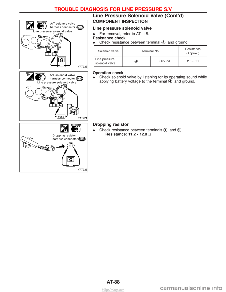
COMPONENT INSPECTION
Line pressure solenoid valve
IFor removal, refer to AT-118.
Resistance check
I Check resistance between terminal q
4and ground.
Solenoid valve
Terminal No.Resistance
(Approx.)
Line pressure
solenoid valve q
4Ground
2.5 - 5W
Operation check
ICheck solenoid valve by listening for its operating sound while
applying battery voltage to the terminal q
4and ground.
Dropping resistor
I
Check resistance between terminals q1andq2.
Resistance: 11.2 - 12.8 W
YAT323
YAT421
YAT325
TROUBLE DIAGNOSIS FOR LINE PRESSURE S/V
Line Pressure Solenoid Valve (Cont'd)
AT-88
http://vnx.su/
Page 902 of 1833
Wiring Diagram Ð AT Ð PNP/SW
YAT406
TROUBLE DIAGNOSIS FOR NON-DETECTABLE ITEMS
AT-89
http://vnx.su/
Page 903 of 1833
YAT407
TROUBLE DIAGNOSIS FOR NON-DETECTABLE ITEMS
Wiring Diagram Ð AT Ð PNP/SW (Cont'd)AT-90
http://vnx.su/
Page 904 of 1833
YAT408
TROUBLE DIAGNOSIS FOR NON-DETECTABLE ITEMS
Wiring Diagram Ð AT Ð PNP/SW (Cont'd)AT-91
http://vnx.su/
Page 905 of 1833
YAT409
TROUBLE DIAGNOSIS FOR NON-DETECTABLE ITEMS
Wiring Diagram Ð AT Ð PNP/SW (Cont'd)AT-92
http://vnx.su/
Page 906 of 1833
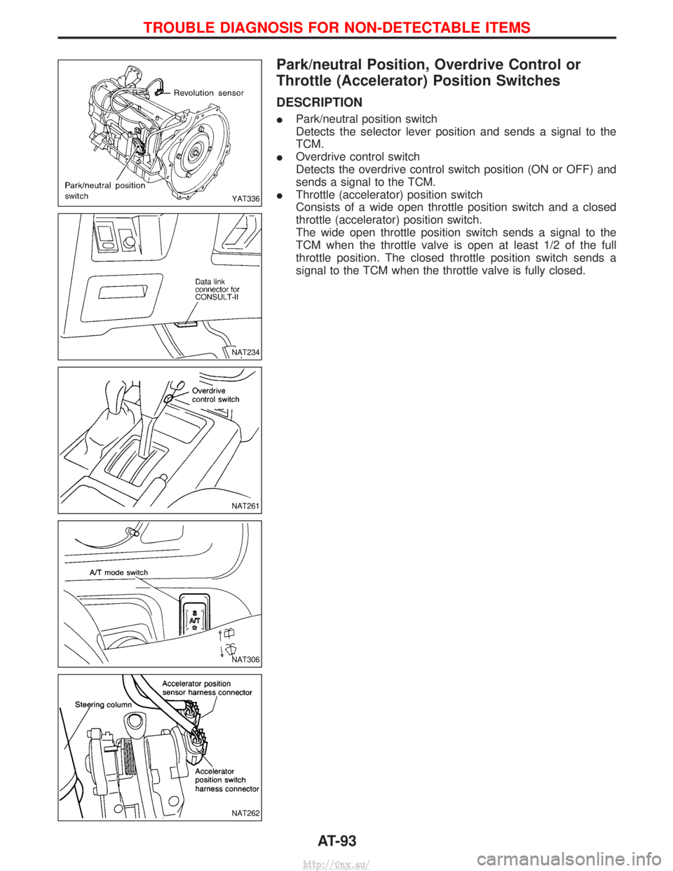
Park/neutral Position, Overdrive Control or
Throttle (Accelerator) Position Switches
DESCRIPTION
IPark/neutral position switch
Detects the selector lever position and sends a signal to the
TCM.
I Overdrive control switch
Detects the overdrive control switch position (ON or OFF) and
sends a signal to the TCM.
I Throttle (accelerator) position switch
Consists of a wide open throttle position switch and a closed
throttle (accelerator) position switch.
The wide open throttle position switch sends a signal to the
TCM when the throttle valve is open at least 1/2 of the full
throttle position. The closed throttle position switch sends a
signal to the TCM when the throttle valve is fully closed.
YAT336
NAT234
NAT261
NAT306
NAT262
TROUBLE DIAGNOSIS FOR NON-DETECTABLE ITEMS
AT-93
http://vnx.su/
Page 907 of 1833
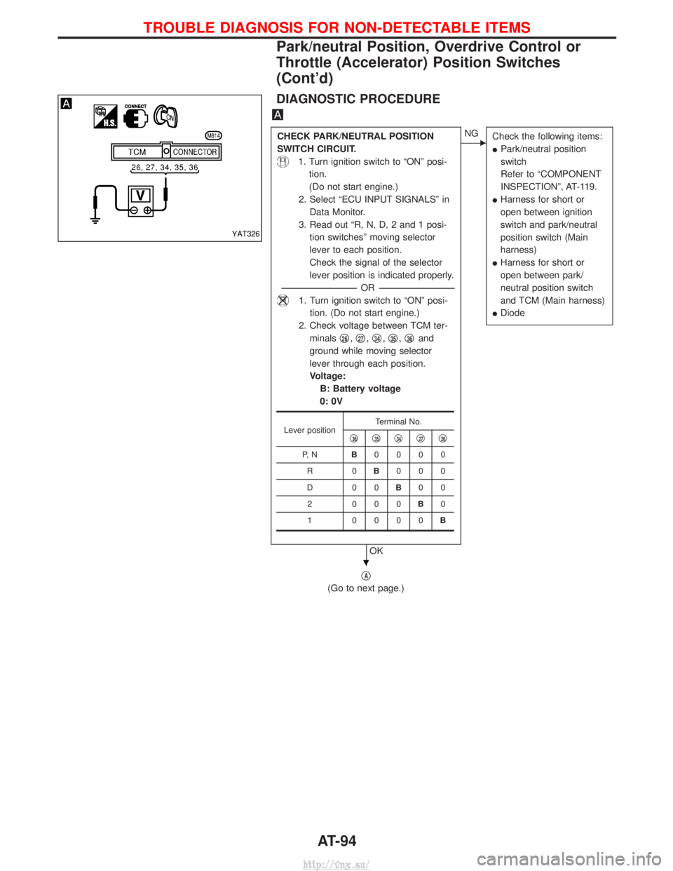
DIAGNOSTIC PROCEDURE
CHECK PARK/NEUTRAL POSITION
SWITCH CIRCUIT.
1. Turn ignition switch to ªONº posi-tion.
(Do not start engine.)
2. Select ªECU INPUT SIGNALSº in Data Monitor.
3. Read out ªR, N, D, 2 and 1 posi- tion switchesº moving selector
lever to each position.
Check the signal of the selector
lever position is indicated properly.
---------------------------------------------------------------------------------------------------------------------- -OR -----------------------------------------------------------------------------------------------------------------------
1. Turn ignition switch to ªONº posi-
tion. (Do not start engine.)
2. Check voltage between TCM ter- minals q
26,q27,q34,q35,q36and
ground while moving selector
lever through each position.
Voltage: B: Battery voltage
0: 0V
OK
ENG Check the following items:
IPark/neutral position
switch
Refer to ªCOMPONENT
INSPECTIONº, AT-119.
I Harness for short or
open between ignition
switch and park/neutral
position switch (Main
harness)
I Harness for short or
open between park/
neutral position switch
and TCM (Main harness)
I Diode
qA
(Go to next page.)
Lever position Terminal No.
q36q35q34q27q26
P, N B0000
R0 B000
D00 B00
2 000 B0
1 0000 B
YAT326
H
TROUBLE DIAGNOSIS FOR NON-DETECTABLE ITEMS
Park/neutral Position, Overdrive Control or
Throttle (Accelerator) Position Switches
(Cont'd)
AT-94
http://vnx.su/
Page 908 of 1833
qA
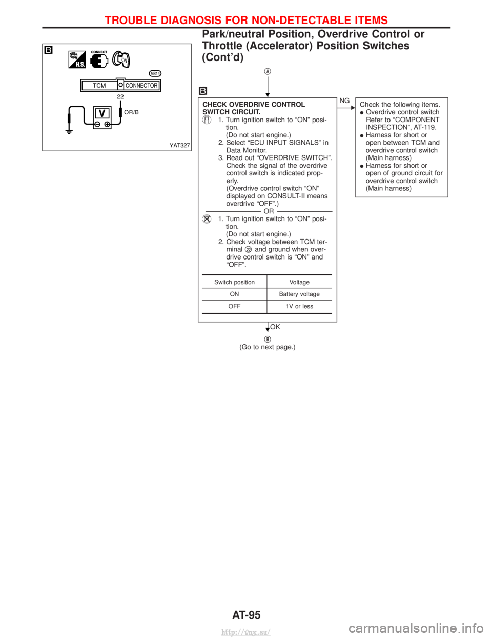
CHECK OVERDRIVE CONTROL
SWITCH CIRCUIT.
1. Turn ignition switch to ªONº posi-tion.
(Do not start engine.)
2. Select ªECU INPUT SIGNALSº in Data Monitor.
3. Read out ªOVERDRIVE SWITCHº. Check the signal of the overdrive
control switch is indicated prop-
erly.
(Overdrive control switch ªONº
displayed on CONSULT-II means
overdrive ªOFFº.)
---------------------------------------------------------------------------------------------------------------------- -OR -----------------------------------------------------------------------------------------------------------------------
1. Turn ignition switch to ªONº posi-
tion.
(Do not start engine.)
2. Check voltage between TCM ter- minal q
22and ground when over-
drive control switch is ªONº and
ªOFFº.
OK
ENG Check the following items.
IOverdrive control switch
Refer to ªCOMPONENT
INSPECTIONº, AT-119.
I Harness for short or
open between TCM and
overdrive control switch
(Main harness)
I Harness for short or
open of ground circuit for
overdrive control switch
(Main harness)
qB(Go to next page.)
Switch position Voltage
ON Battery voltage
OFF 1V or less
YAT327
H
H
TROUBLE DIAGNOSIS FOR NON-DETECTABLE ITEMS
Park/neutral Position, Overdrive Control or
Throttle (Accelerator) Position Switches
(Cont'd)
AT-95
http://vnx.su/
Page 909 of 1833
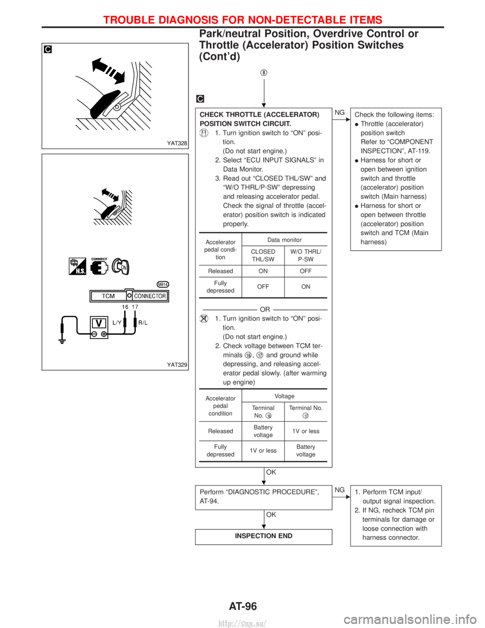
qB
CHECK THROTTLE (ACCELERATOR)
POSITION SWITCH CIRCUIT.
1. Turn ignition switch to ªONº posi-tion.
(Do not start engine.)
2. Select ªECU INPUT SIGNALSº in Data Monitor.
3. Read out ªCLOSED THL/SWº and ªW/O THRL/P-SWº depressing
and releasing accelerator pedal.
Check the signal of throttle (accel-
erator) position switch is indicated
properly.
---------------------------------------------------------------------------------------------------------------------- -OR -----------------------------------------------------------------------------------------------------------------------
1. Turn ignition switch to ªONº posi-
tion.
(Do not start engine.)
2. Check voltage between TCM ter- minals q
16,q17and ground while
depressing, and releasing accel-
erator pedal slowly. (after warming
up engine)
OK
ENG Check the following items:
IThrottle (accelerator)
position switch
Refer to ªCOMPONENT
INSPECTIONº, AT-119.
I Harness for short or
open between ignition
switch and throttle
(accelerator) position
switch (Main harness)
I Harness for short or
open between throttle
(accelerator) position
switch and TCM (Main
harness)
Perform ªDIAGNOSTIC PROCEDUREº,
AT-94.
OK
ENG
1. Perform TCM input/
output signal inspection.
2. If NG, recheck TCM pin terminals for damage or
loose connection with
harness connector.
INSPECTION END
Accelerator
pedal condi- tion Data monitor
CLOSED THL/SW W/O THRL/
P-SW
Released ON OFF Fully
depressed OFF ON
Accelerator
pedal
condition Voltage
Terminal No. q
16Terminal No.
q17
Released Battery
voltage 1V or less
Fully
depressed 1V or less Battery
voltage
YAT328
YAT329
H
H
H
TROUBLE DIAGNOSIS FOR NON-DETECTABLE ITEMS
Park/neutral Position, Overdrive Control or
Throttle (Accelerator) Position Switches
(Cont'd)
AT-96
http://vnx.su/
Page 910 of 1833
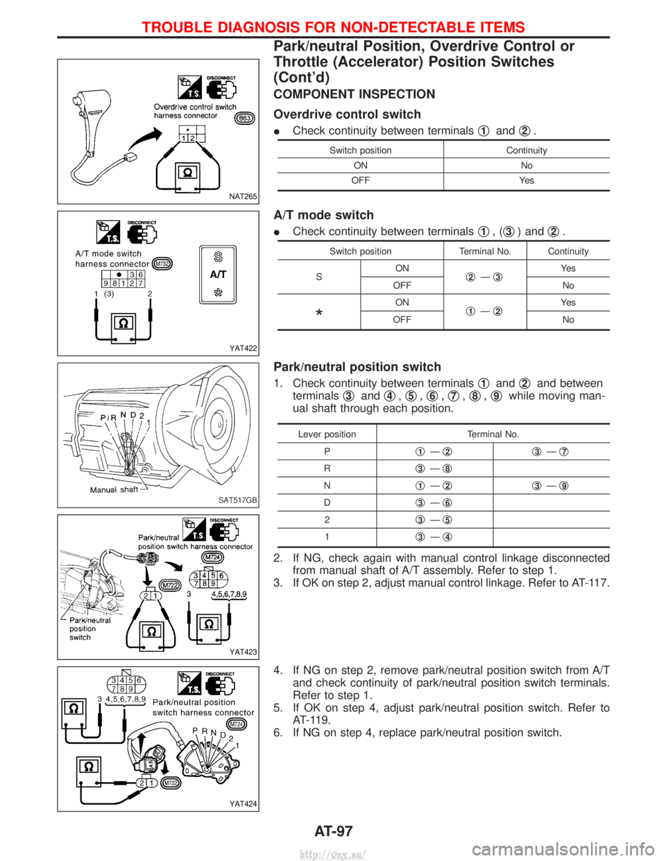
COMPONENT INSPECTION
Overdrive control switch
ICheck continuity between terminals q1andq2.
Switch position
Continuity
ON No
OFF Yes
A/T mode switch
ICheck continuity between terminals q1,(q3) and q2.
Switch position
Terminal No. Continuity
S ON
q
2Ðq3Ye s
OFF No
*
ON q1Ðq2Ye s
OFF No
Park/neutral position switch
1. Check continuity between terminals q1andq2and between
terminals q
3andq4,q5,q6,q7,q8,q9while moving man-
ual shaft through each position.
Lever position Terminal No.
P q
1Ðq2q3Ðq7
R q3Ðq8
N q1Ðq2q3Ðq9
D q3Ðq6
2 q3Ðq5
1 q3Ðq4
2. If NG, check again with manual control linkage disconnected
from manual shaft of A/T assembly. Refer to step 1.
3. If OK on step 2, adjust manual control linkage. Refer to AT-117.
4. If NG on step 2, remove park/neutral position switch from A/T and check continuity of park/neutral position switch terminals.
Refer to step 1.
5. If OK on step 4, adjust park/neutral position switch. Refer to AT-119.
6. If NG on step 4, replace park/neutral position switch.
NAT265
YAT422
SAT517GB
YAT423
YAT424
TROUBLE DIAGNOSIS FOR NON-DETECTABLE ITEMS
Park/neutral Position, Overdrive Control or
Throttle (Accelerator) Position Switches
(Cont'd)
AT-97
http://vnx.su/
Trending: tire size, engine coolant, check transmission fluid, recommended oil, Location, Ignition wiring, air bleeding
