NISSAN TIIDA 2007 Service Repair Manual
Manufacturer: NISSAN, Model Year: 2007, Model line: TIIDA, Model: NISSAN TIIDA 2007Pages: 5883, PDF Size: 78.95 MB
Page 181 of 5883
BCS-46
< ECU DIAGNOSIS >
BCM (BODY CONTROL MODULE)
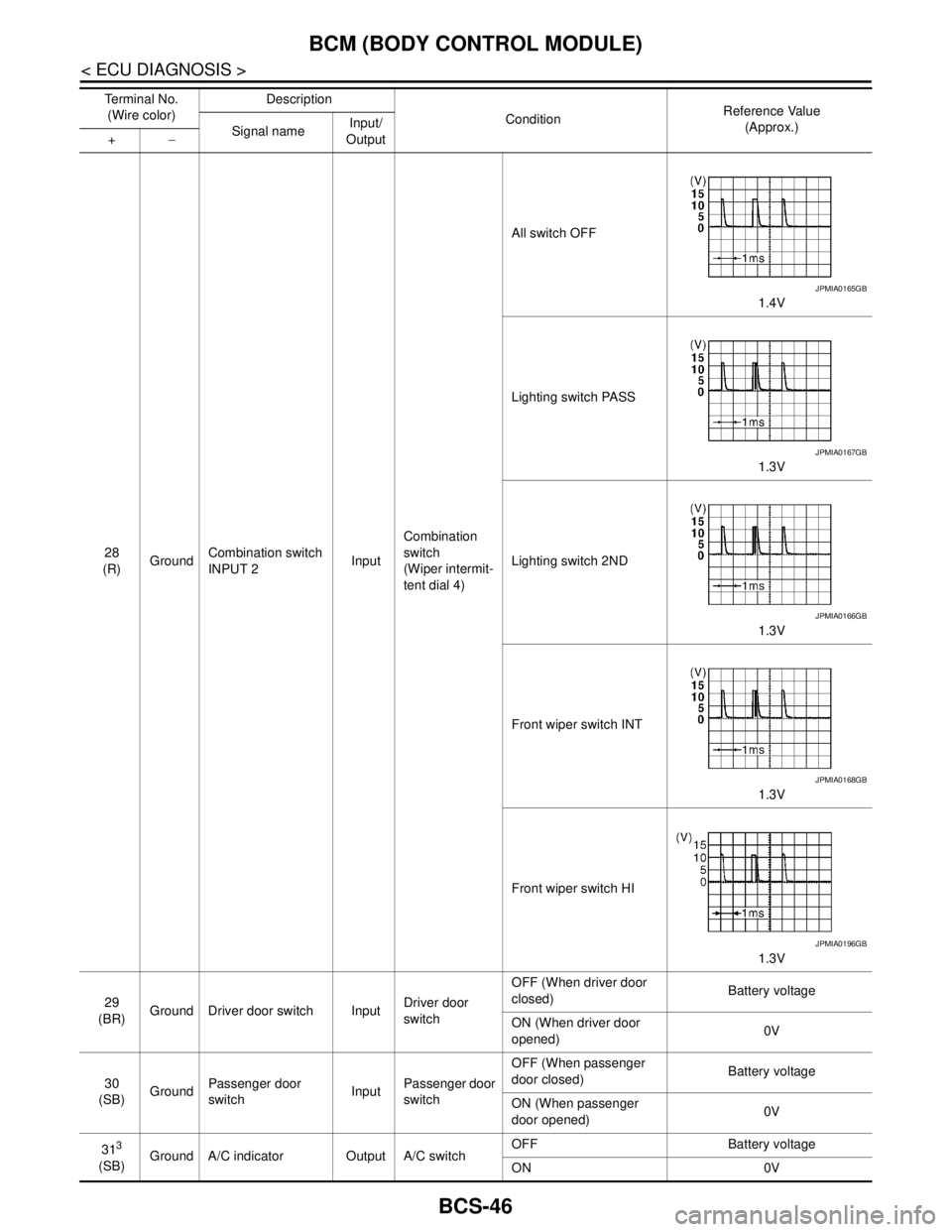
28
(R)GroundCombination switch
INPUT 2InputCombination
switch
(Wiper intermit-
tent dial 4)All switch OFF
1.4V
Lighting switch PASS
1.3V
Lighting switch 2ND
1.3V
Front wiper switch INT
1.3V
Front wiper switch HI
1.3V
29
(BR)Ground Driver door switch InputDriver door
switchOFF (When driver door
closed)Battery voltage
ON (When driver door
opened)0V
30
(SB)GroundPassenger door
switchInputPassenger door
switchOFF (When passenger
door closed)Battery voltage
ON (When passenger
door opened)0V
31
3
(SB)Ground A/C indicator Output A/C switchOFF Battery voltage
ON 0V Te r m i n a l N o .
(Wire color)Description
ConditionReference Value
(Approx.)
Signal nameInput/
Output +−
JPMIA0165GB
JPMIA0167GB
JPMIA0166GB
JPMIA0168GB
JPMIA0196GB
Page 182 of 5883
BCS
BCM (BODY CONTROL MODULE)
BCS-47
< ECU DIAGNOSIS >
C
D
E
F
G
H
I
J
K
L B A
O
P N
324
(LG)GroundDoor lock status indi-
catorOutputDoor lock status
indicatorON Battery voltage
OFF 0V
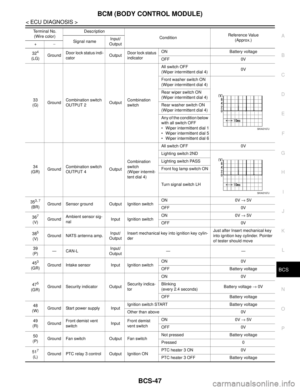
33
(G)GroundCombination switch
OUTPUT 2OutputCombination
switchAll switch OFF
(Wiper intermittent dial 4)0V
Front washer switch ON
(Wiper intermittent dial 4)
Rear wiper switch ON
(Wiper intermittent dial 4)
Rear washer switch ON
(Wiper intermittent dial 4)
Any of the condition below
with all switch OFF
Wiper intermittent dial 1
Wiper intermittent dial 5
Wiper intermittent dial 6
34
(GR)GroundCombination switch
OUTPUT 4OutputCombination
switch
(Wiper intermit-
tent dial 4)All switch OFF 0V
Lighting switch 2ND
Lighting switch PASS
Front fog lamp switch ON
Turn signal switch LH
35
3, 7
(BR)Ground Sensor ground Output Ignition switchON 0V → 5V
OFF 0V
36
7
(V)GroundAmbient sensor sig-
nalInput Ignition switchON 0V → 5V
OFF 0V
38
5
(V)Ground NATS antenna amp.Input/
OutputInsert mechanical key into ignition key cylin-
derJust after Insert mechanical key
into ignition key cylinder. Pointer
of tester should move
39
(P)—CAN-LInput/
Output——
45
3
(GR)Ground Intake sensor Input Ignition switchON 0V
OFF Battery voltage
47
5
(GR)Ground Security indicator OutputSecurity indica-
torON 0V
Blinking
(every 2.4 seconds)Battery voltage → 0V
OFF Battery voltage
48
(W)Ground Start power supply InputIgnition switch START Battery voltage
Other than above 0V
49
(R)GroundFront demist vent
switchInputFront demist
vent switchON 0V → 5V
OFF 0V
50
(P)Ground Fan switch Output Fan switchNot pressed Battery voltage
Pressed 0
51
7
(L)Ground PTC relay 3 control Output Ignition ONPTC heater 3 ON 0V
PTC heater 3 OFF Battery voltage Terminal No.
(Wire color)Description
ConditionReference Value
(Approx.)
Signal nameInput/
Output +−
SKIA2167J
SKIA2167J
Page 183 of 5883
BCS-48
< ECU DIAGNOSIS >
BCM (BODY CONTROL MODULE)
527
(GR)Ground PTC relay 2 control Output Ignition ONPTC heater 2 ON 0V
PTC heater 2 OFF Battery voltage
58
(Y)Ground Door unlock sensor Input Driver doorLock Battery voltage
Unlock 0V
59
(O)Ground Rear door switch LH InputRear door
switch LHOFF (When rear door LH
closed) Battery voltage
ON (When rear door LH
opened)0V
60
(GR)Ground Rear door switch RH InputRear door
switch RHOFF (When rear door RH
closed) Battery voltage
ON (When rear door RH
opened)0V
61
3
(O)Ground A/C switch Output A/C switchNot pressed Battery voltage
Pressed 0V
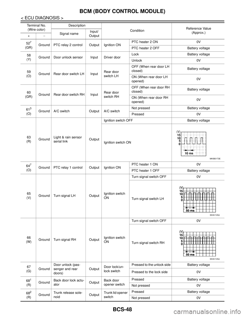
63
(R)GroundLight & rain sensor
serial linkOutputIgnition switch OFF Battery voltage
Ignition switch ON
64
7
(O)Ground PTC relay 1 control Output Ignition ONPTC heater 1 ON 0V
PTC heater 1 OFF Battery voltage
65
(V)Ground Turn signal LH OutputIgnition switch
ONTurn signal switch OFF 0V
Turn signal switch LH
66
(W)Ground Turn signal RH OutputIgnition switch
ONTurn signal switch OFF 0V
Turn signal switch RH
67
(G)GroundDoor unlock (pas-
senger and rear
doors)OutputDoor lock/un-
lock switchPressed to the unlock side Battery voltage
Pressed to the lock side 0V
68
1
(R)GroundBack door lock actu-
atorOutputBack door
opener switchPressed Battery voltage
Not pressed 0V
68
2
(R)GroundTrunk release sole-
noidOutputTrunk lid opener
switchPressed Battery voltage
Not pressed 0V Te r m i n a l N o .
(Wire color)Description
ConditionReference Value
(Approx.)
Signal nameInput/
Output +−
MKIB0173E
SKIA1120J
SKIA1120J
Page 184 of 5883

BCS
BCM (BODY CONTROL MODULE)
BCS-49
< ECU DIAGNOSIS >
C
D
E
F
G
H
I
J
K
L B A
O
P N
1: Hatchback
2: Sedan
3: Manual A/C
4: Superlock
5: Remote keyless entry
6: Intelligent Key
7: LHD diesel69
(G)Ground Rear fog lamp OutputLighting switch
1ST and front
fog lamp switch
ONRear fog lamp switch OFF 0V
Rear fog lamp switch ON Battery voltage
70
(B)Ground Ground — — 0V
71
1
(V)Ground Rear wiper motor OutputRear wiper switch OFF 0V
Rear wiper switch ON Battery voltage
72
(LG)GroundBattery power sup-
plyInput — Battery voltage
73
(R)GroundInterior room lamp
power supplyOutputAfter passing the interior room lamp battery
saver operation time0V
Any other time after passing the interior room
lamp battery saver operation timeBattery voltage
74
(Y)GroundBattery power sup-
plyInput — Battery voltage
75
4
(V)Ground Super lock OutputWhen lock button of keyfob or Intelligent Key
is not pressed 0V
When lock button of keyfob or Intelligent Key
is pressed Battery voltage
76
(G)Ground Driver door unlock OutputDoor lock/un-
lock switchPressed to the unlock side Battery voltage
Pressed to the lock side 0V
77
(SB)Ground Door lock (All) OutputDoor lock/un-
lock switchPressed to the unlock side 0V
Pressed to the lock side Battery voltage
78
(L)GroundPower window pow-
er supplyOutput Ignition switchOFF or ACC 0V
ON Battery voltage
79
(Y)GroundBattery power sup-
plyInput — Battery voltage Terminal No.
(Wire color)Description
ConditionReference Value
(Approx.)
Signal nameInput/
Output +−
Page 185 of 5883
BCS-50
< ECU DIAGNOSIS >
BCM (BODY CONTROL MODULE)
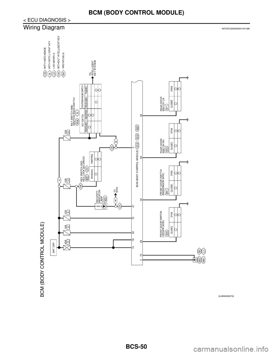
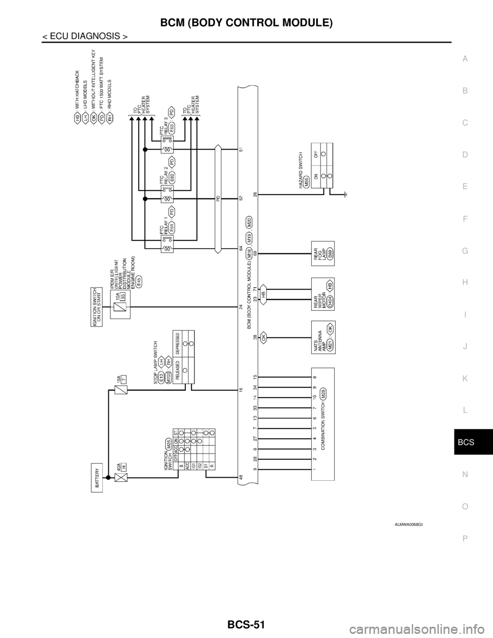
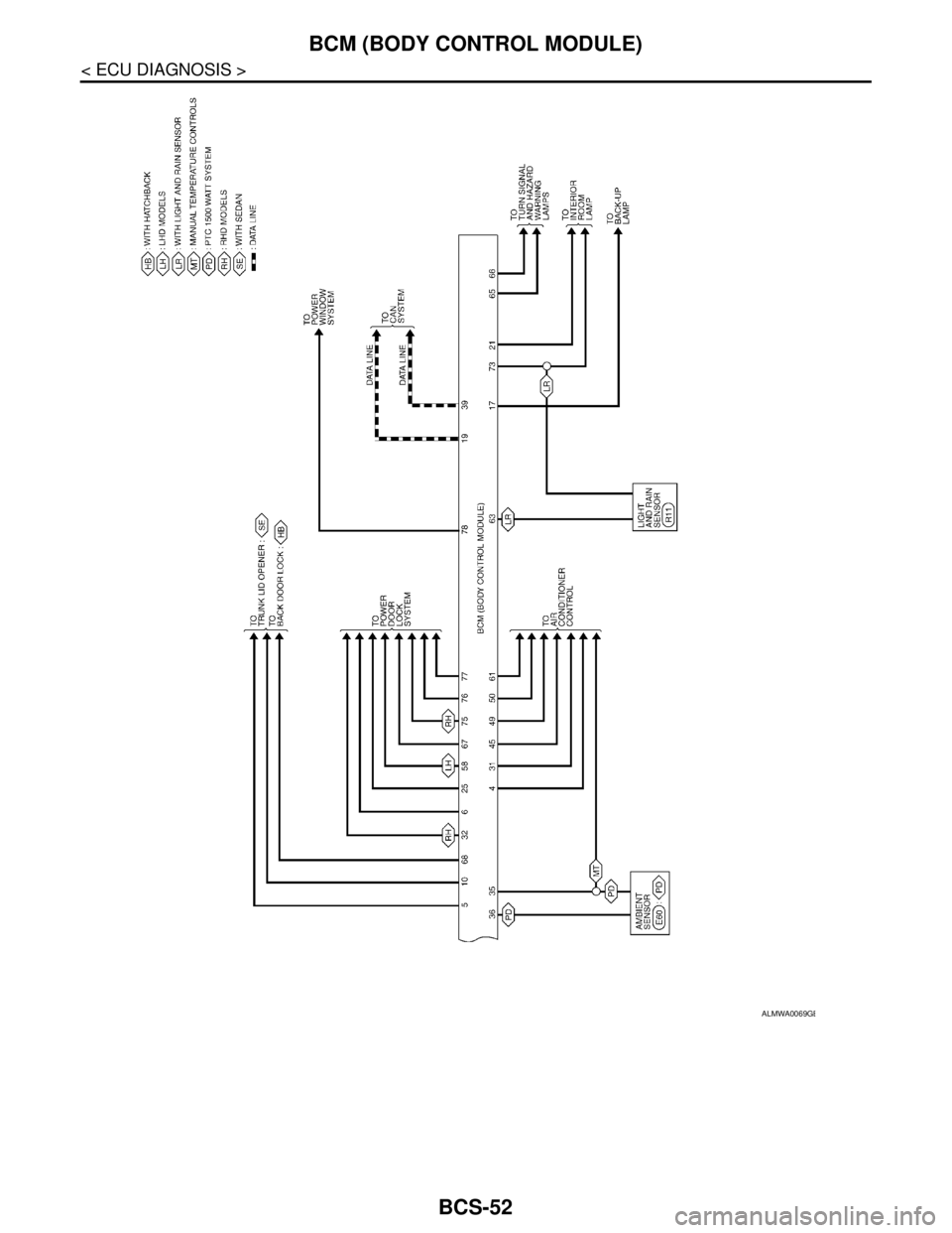
Wiring Diagram
INFOID:0000000001451496
ALMWA0067GB
Page 186 of 5883
BCS
BCM (BODY CONTROL MODULE)
BCS-51
< ECU DIAGNOSIS >
C
D
E
F
G
H
I
J
K
L B A
O
P N
ALMWA0068GB
Page 187 of 5883
BCS-52
< ECU DIAGNOSIS >
BCM (BODY CONTROL MODULE)
ALMWA0069GB
Page 188 of 5883
BCS
BCM (BODY CONTROL MODULE)
BCS-53
< ECU DIAGNOSIS >
C
D
E
F
G
H
I
J
K
L B A
O
P N
DTC Inspection Priority ChartINFOID:0000000001451498
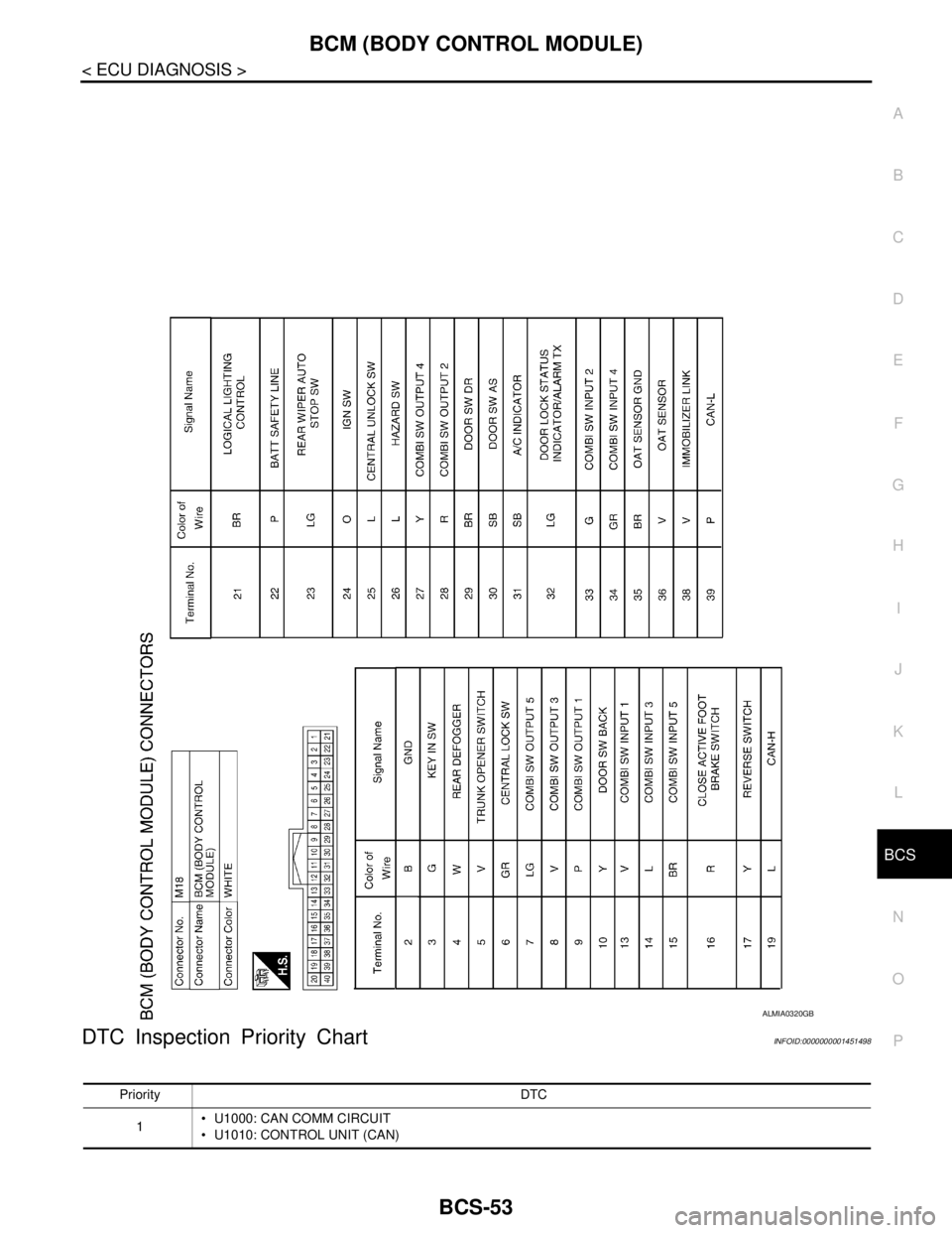
ALMIA0320GB
Priority DTC
1 U1000: CAN COMM CIRCUIT
U1010: CONTROL UNIT (CAN)
Page 189 of 5883

BCS-54
< ECU DIAGNOSIS >
BCM (BODY CONTROL MODULE)
DTC Index
INFOID:0000000001451499
NOTE:
Details of time display
CRNT: Displays when there is a malfunction now or after returning to the normal condition until turning igni-
tion switch OFF → ON again.
PAST: Displays when there is a malfunction that is detected in the past and stored.
1 - 39: Displayed if any previous malfunction is present when current condition is normal. It increases like 1
→ 2 → 3...38 → 39 after returning to the normal condition whenever ignition switch OFF → ON. The counter
remains at 39 even if the number of cycles exceeds it. It is counted from 1 again when turning ignition switch
OFF → ON after returning to the normal condition if the malfunction is detected again.
CONSULT display TIME Fail-safe Refer to
No DTC is detected.
further testing
may be required.—— — —
U1000: CAN COMM CIRCUIT 0 1 - 39 —BCS-28
U1010: CONTROL UNIT (CAN) 0 1 - 39 —BCS-29
Page 190 of 5883
BCS
COMBINATION SWITCH SYSTEM SYMPTOMS
BCS-55
< SYMPTOM DIAGNOSIS >
C
D
E
F
G
H
I
J
K
L B A
O
P N
SYMPTOM DIAGNOSIS
COMBINATION SWITCH SYSTEM SYMPTOMS
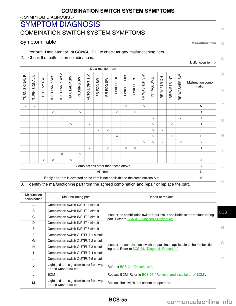
Symptom TableINFOID:0000000001451500
1. Perform “Data Monitor” of CONSULT-III to check for any malfunctioning item.
2. Check the malfunction combinations.
Malfunction item: ×
3. Identify the malfunctioning part from the agreed combination and repair or replace the part.
Data monitor item
Malfunction combi-
nation
TURN SIGNAL R
TURN SIGNAL L
HI BEAM SW
HEAD LAMP SW 1
HEAD LAMP SW 2
TAIL LAMP SW
PASSING SW
AUTO LIGHT SW
FR FOG SW
RR FOG SW
FR WIPER HI
FR WIPER LOW
FR WIPER INT
FR WASHER SW
INT VOLUME
RR WIPER ON
RR WIPER INT
RR WASHER SW
×× × ×A
×× ××B
×× × ×C
×× ××D
×× ××E
×××F
××× ×G
××××H
××××I
××××J
Combinations other than those above K
All Items L
If only one item is detected or the item is not applicable to the combinations A to L M
Malfunction
combinationMalfunctioning part Repair or replace
A Combination switch INPUT 1 circuit
Inspect the combination switch input circuit applicable to the malfunctioning
part. Refer to BCS-31, "
Diagnosis Procedure". B Combination switch INPUT 2 circuit
C Combination switch INPUT 3 circuit
D Combination switch INPUT 4 circuit
E Combination switch INPUT 5 circuit
F Combination switch OUTPUT 1 circuit
Inspect the combination switch output circuit applicable to the malfunction-
ing part. Refer to BCS-33, "
Diagnosis Procedure". G Combination switch OUTPUT 2 circuit
H Combination switch OUTPUT 3 circuit
I Combination switch OUTPUT 4 circuit
J Combination switch OUTPUT 5 circuit
KLight and turn signal switch or front wip-
er and washer switchRefer to BCS-34, "
Description".
L BCM Replace BCM. Refer to BCS-57, "
Removal and Installation of BCM".
MLight and turn signal switch or front wip-
er and washer switchReplace the switch that cannot be operated.