NISSAN TIIDA 2007 Service Repair Manual
TIIDA 2007
NISSAN
NISSAN
https://www.carmanualsonline.info/img/5/57395/w960_57395-0.png
NISSAN TIIDA 2007 Service Repair Manual
Trending: wheel Bearing, Guage, BRC 86, wiper fluid, oil level, door lock, adding oil
Page 3111 of 5883
SQUEAK AND RATTLE TROUBLE DIAGNOSIS
EXT-7
< ON-VEHICLE MAINTENANCE >
C
D
E
F
G
H
I
J
L
MA
B
EXT
N
O
P
4. A loose license plate or bracket
Most of these incidents can be repaired by adjusting, securing or insulating the item(s) or component(s) caus-
ing the noise.
SUNROOF/HEADLINING
Noises in the sunroof/headlining area can often be traced to one of the following:
1. Sunroof lid, rail, linkage or seals making a rattle or light knocking noise
2. Sun visor shaft shaking in the holder
3. Front or rear windshield touching headliner and squeaking
Again, pressing on the components to stop the noise while duplicating the conditions can isolate most of these
incidents. Repairs usually consist of insulating with felt cloth tape.
OVERHEAD CONSOLE (FRONT AND REAR)
Overhead console noises are often caused by the console panel clips not being engaged correctly. Most of
these incidents are repaired by pushing up on the console at the clip locations until the clips engage.
In addition look for:
1. Loose harness or harness connectors.
2. Front console map/reading lamp lens loose.
3. Loose screws at console attachment points.
SEATS
When isolating seat noise it's important to note the position the seat is in and the load placed on the seat when
the noise is present. These conditions should be duplicated when verifying and isolating the cause of the
noise.
Cause of seat noise include:
1. Headrest rods and holder
2. A squeak between the seat pad cushion and frame
3. The rear seatback lock and bracket
These noises can be isolated by moving or pressing on the suspected components while duplicating the con-
ditions under which the noise occurs. Most of these incidents can be repaired by repositioning the component
or applying urethane tape to the contact area.
UNDERHOOD
Some interior noise may be caused by components under the hood or on the engine wall. The noise is then
transmitted into the passenger compartment.
Causes of transmitted underhood noise include:
1. Any component installed on the engine wall
2. Components that pass through the engine wall
3. Engine wall mounts and connectors
4. Loose radiator pins
5. Hood bumpers out of adjustment
6. Hood striker out of adjustment
These noises can be difficult to isolate since they cannot be reached from the interior of the vehicle. The best
method is to secure, move or insulate one component at a time and test drive the vehicle. Also, engine RPM
or load can be changed to isolate the noise. Repairs can usually be made by moving, adjusting, securing, or
insulating the component causing the noise.
Page 3112 of 5883
EXT-8
< ON-VEHICLE MAINTENANCE >
SQUEAK AND RATTLE TROUBLE DIAGNOSIS
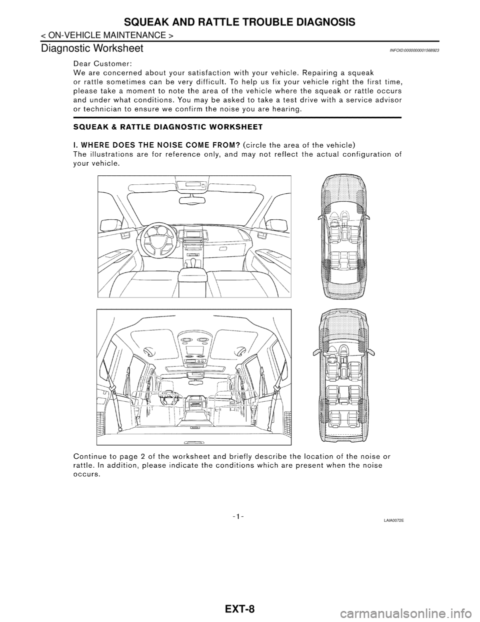
Diagnostic Worksheet
INFOID:0000000001568923
LAIA0072E
Page 3113 of 5883
SQUEAK AND RATTLE TROUBLE DIAGNOSIS
EXT-9
< ON-VEHICLE MAINTENANCE >
C
D
E
F
G
H
I
J
L
MA
B
EXT
N
O
P
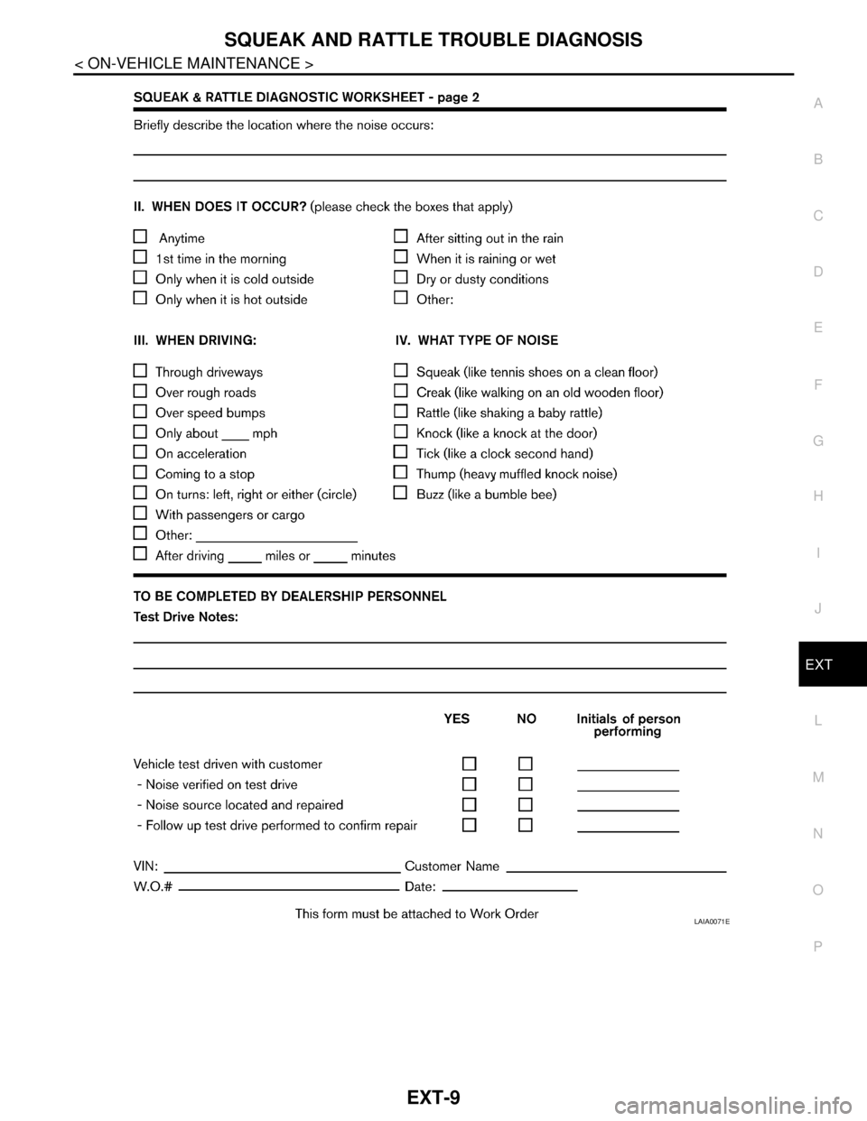
LAIA0071E
Page 3114 of 5883
EXT-10
< ON-VEHICLE REPAIR >
CLIP AND FASTENER
ON-VEHICLE REPAIR
CLIP AND FASTENER
DescriptionINFOID:0000000001568924
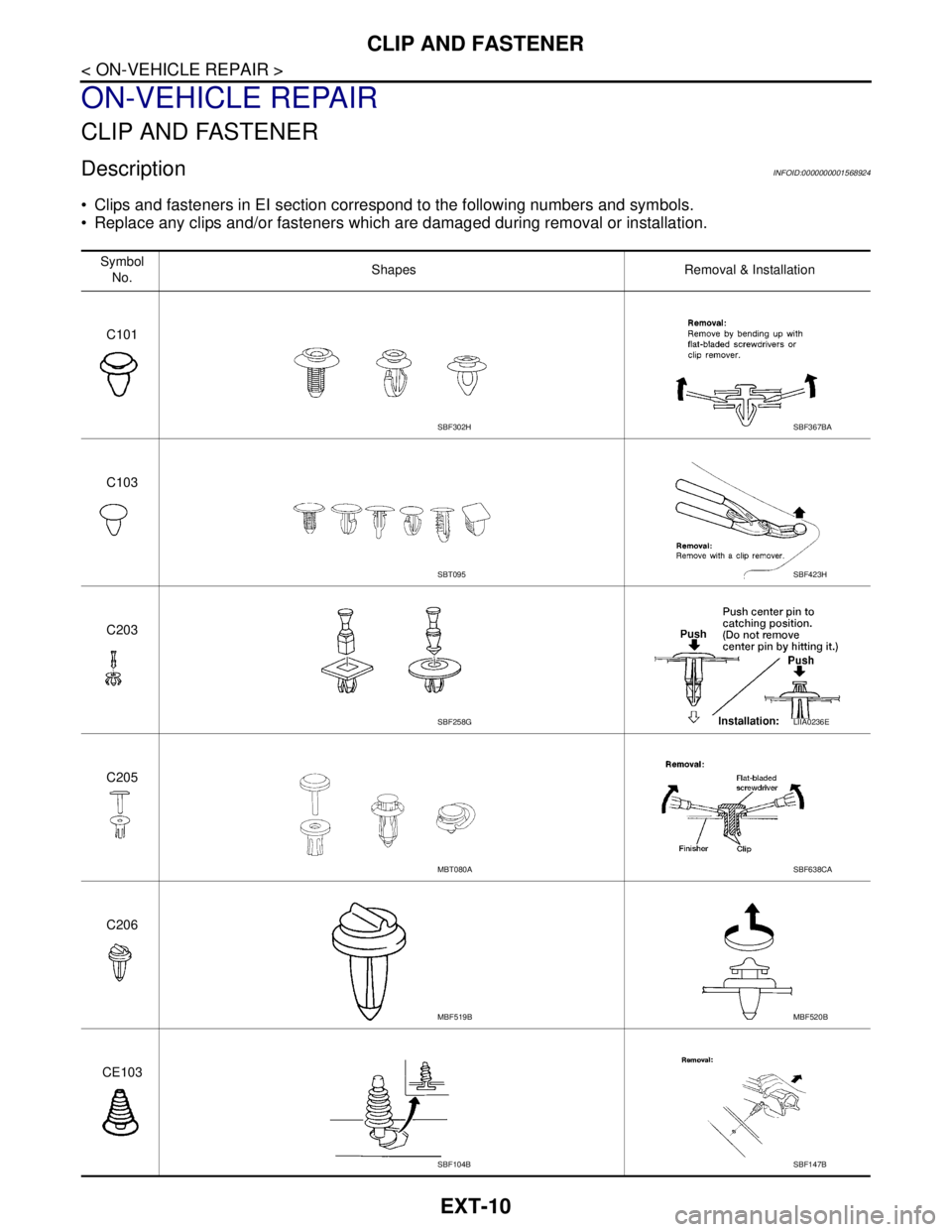
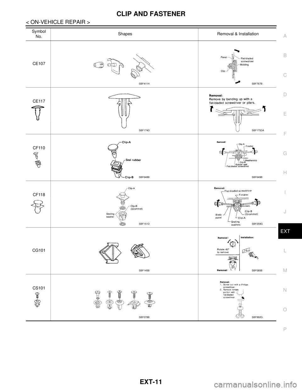
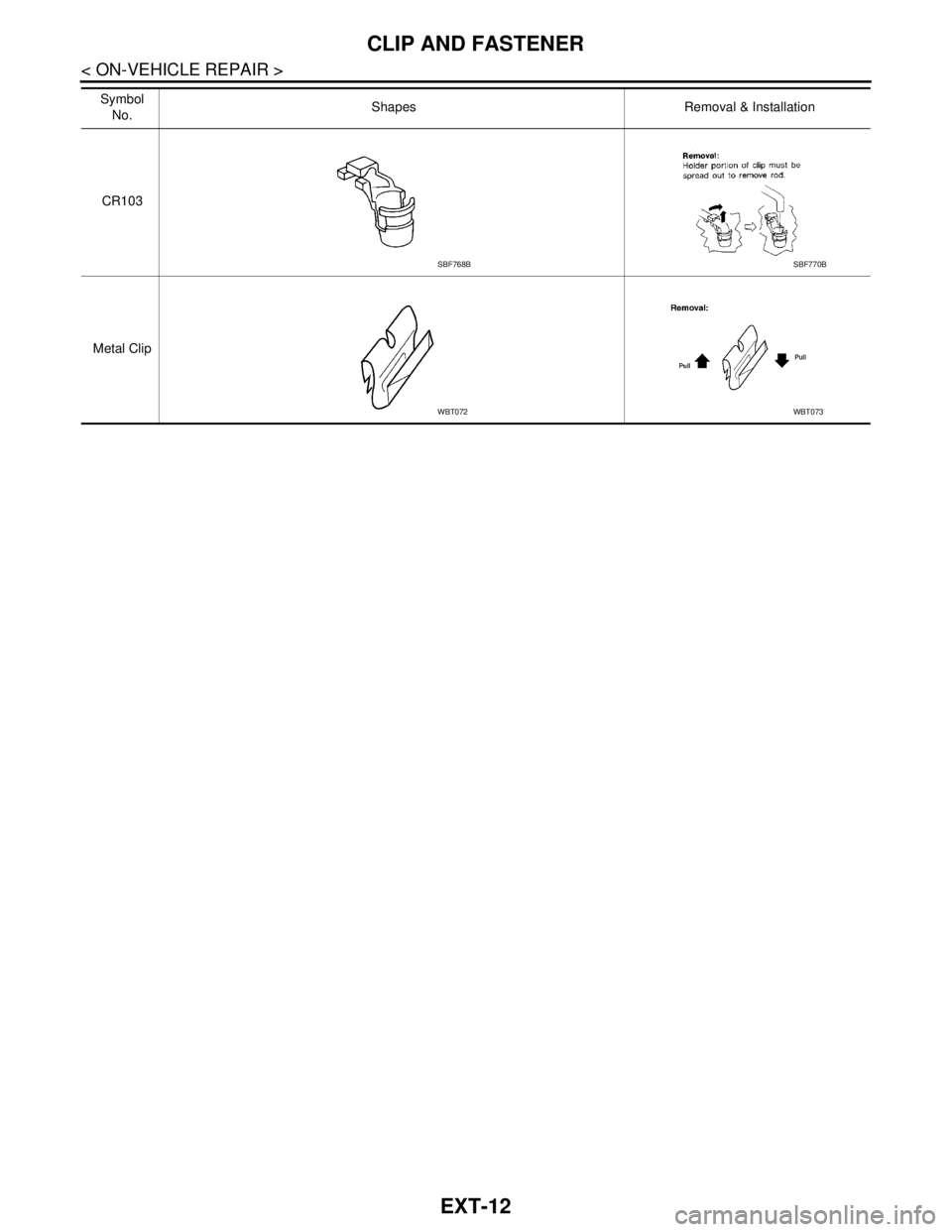
Clips and fasteners in EI section correspond to the following numbers and symbols.
Replace any clips and/or fasteners which are damaged during removal or installation.
Symbol
No.Shapes Removal & Installation
C101
C103
C203
C205
C206
CE103
SBF302HSBF367BA
SBT095SBF423H
SBF258GLIIA0236E
MBT080ASBF638CA
MBF519BMBF520B
SBF104BSBF147B
Page 3115 of 5883
CLIP AND FASTENER
EXT-11
< ON-VEHICLE REPAIR >
C
D
E
F
G
H
I
J
L
MA
B
EXT
N
O
P
CE107
CE117
CF110
CF118
CG101
CS101 Symbol
No.Shapes Removal & Installation
SBF411HSBF767B
SBF174DSBF175DA
SBF648BSBF649B
SBF151DSBF259G
SBF145BSBF085B
SBF078BSBF992G
Page 3116 of 5883
EXT-12
< ON-VEHICLE REPAIR >
CLIP AND FASTENER
CR103
Metal ClipSymbol
No.Shapes Removal & Installation
SBF768BSBF770B
WBT072WBT073
Page 3117 of 5883
FRONT BUMPER
EXT-13
< ON-VEHICLE REPAIR >
C
D
E
F
G
H
I
J
L
MA
B
EXT
N
O
P
FRONT BUMPER
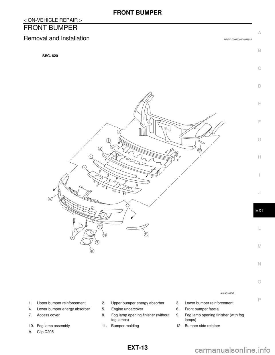
Removal and InstallationINFOID:0000000001568925
1. Upper bumper reinforcement 2. Upper bumper energy absorber 3. Lower bumper reinforcement
4. Lower bumper energy absorber 5. Engine undercover 6. Front bumper fascia
7. Access cover 8. Fog lamp opening finisher (without
fog lamps)9. Fog lamp opening finisher (with fog
lamps)
10. Fog lamp assembly 11. Bumper molding 12. Bumper side retainer
A. Clip C205
ALIIA0108GB
Page 3118 of 5883
EXT-14
< ON-VEHICLE REPAIR >
FRONT BUMPER
CAUTION:
Bumper fascia is made of resin. Do not apply strong force to it, and be careful to prevent contact with
oil.
REMOVAL
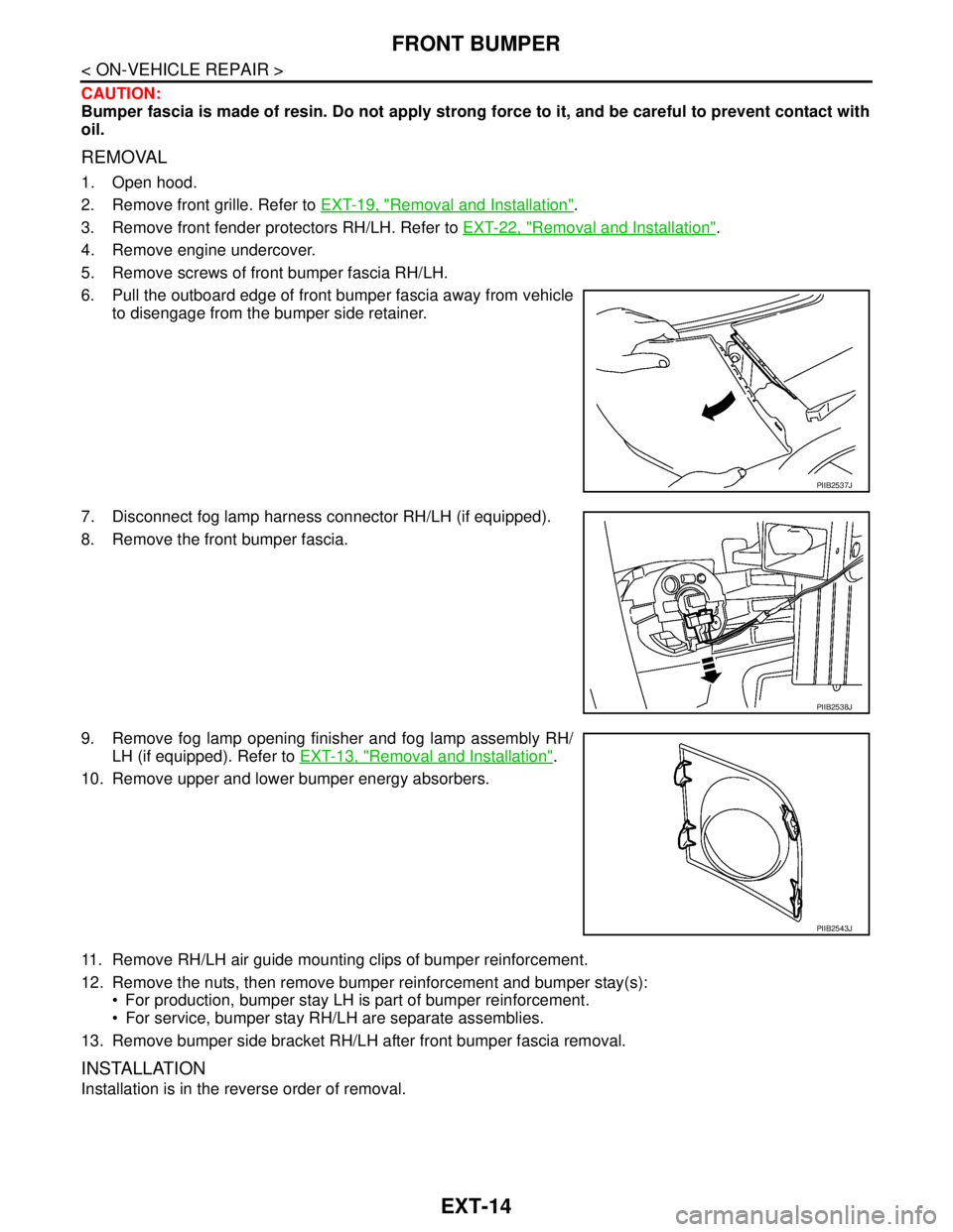
1. Open hood.
2. Remove front grille. Refer to EXT-19, "
Removal and Installation".
3. Remove front fender protectors RH/LH. Refer to EXT-22, "
Removal and Installation".
4. Remove engine undercover.
5. Remove screws of front bumper fascia RH/LH.
6. Pull the outboard edge of front bumper fascia away from vehicle
to disengage from the bumper side retainer.
7. Disconnect fog lamp harness connector RH/LH (if equipped).
8. Remove the front bumper fascia.
9. Remove fog lamp opening finisher and fog lamp assembly RH/
LH (if equipped). Refer to EXT-13, "
Removal and Installation".
10. Remove upper and lower bumper energy absorbers.
11. Remove RH/LH air guide mounting clips of bumper reinforcement.
12. Remove the nuts, then remove bumper reinforcement and bumper stay(s):
For production, bumper stay LH is part of bumper reinforcement.
For service, bumper stay RH/LH are separate assemblies.
13. Remove bumper side bracket RH/LH after front bumper fascia removal.
INSTALLATION
Installation is in the reverse order of removal.
PIIB2537J
PIIB2538J
PIIB2543J
Page 3119 of 5883
REAR BUMPER
EXT-15
< ON-VEHICLE REPAIR >
C
D
E
F
G
H
I
J
L
MA
B
EXT
N
O
P
REAR BUMPER
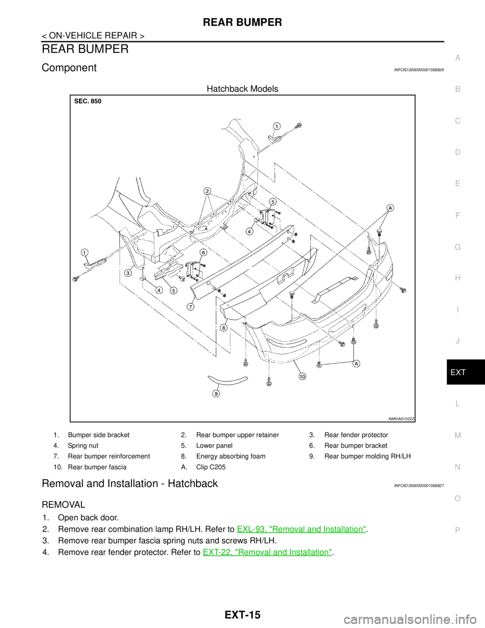
ComponentINFOID:0000000001568926
Hatchback Models
Removal and Installation - HatchbackINFOID:0000000001568927
REMOVAL
1. Open back door.
2. Remove rear combination lamp RH/LH. Refer to EXL-93, "
Removal and Installation".
3. Remove rear bumper fascia spring nuts and screws RH/LH.
4. Remove rear fender protector. Refer to EXT-22, "
Removal and Installation".
AWKIA0102ZZ
1. Bumper side bracket 2. Rear bumper upper retainer 3. Rear fender protector
4. Spring nut 5. Lower panel 6. Rear bumper bracket
7. Rear bumper reinforcement 8. Energy absorbing foam 9. Rear bumper molding RH/LH
10. Rear bumper fascia A. Clip C205
Page 3120 of 5883
EXT-16
< ON-VEHICLE REPAIR >
REAR BUMPER
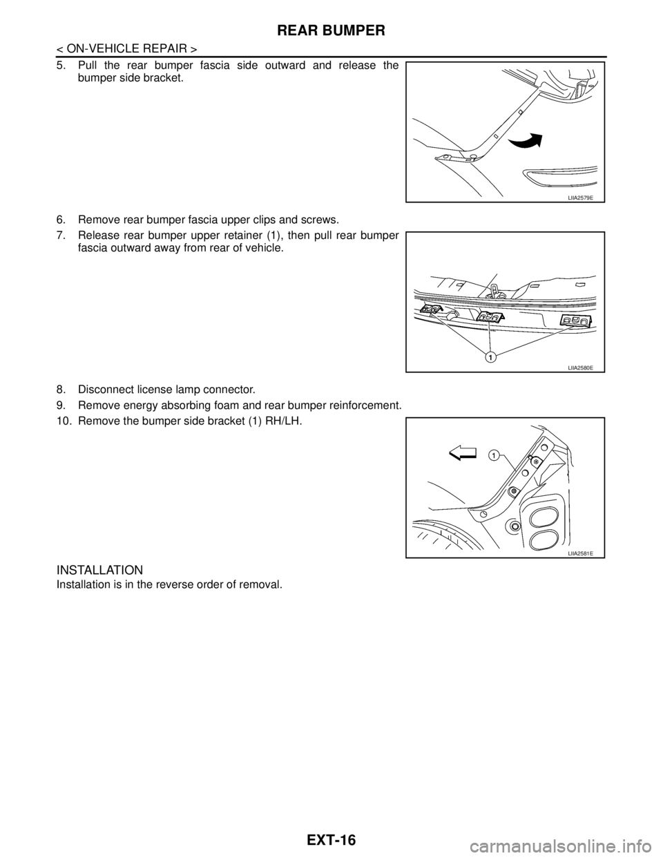
5. Pull the rear bumper fascia side outward and release the
bumper side bracket.
6. Remove rear bumper fascia upper clips and screws.
7. Release rear bumper upper retainer (1), then pull rear bumper
fascia outward away from rear of vehicle.
8. Disconnect license lamp connector.
9. Remove energy absorbing foam and rear bumper reinforcement.
10. Remove the bumper side bracket (1) RH/LH.
INSTALLATION
Installation is in the reverse order of removal.
LIIA2579E
LIIA2580E
LIIA2581E
Trending: battery location, reverse light, instrument cluster, headlights, SRS, ABS, fuel pump

