NISSAN TIIDA 2007 Service Repair Manual
Manufacturer: NISSAN, Model Year: 2007, Model line: TIIDA, Model: NISSAN TIIDA 2007Pages: 5883, PDF Size: 78.95 MB
Page 3131 of 5883
DOOR OUTSIDE MOLDING
EXT-27
< ON-VEHICLE REPAIR >
C
D
E
F
G
H
I
J
L
MA
B
EXT
N
O
P
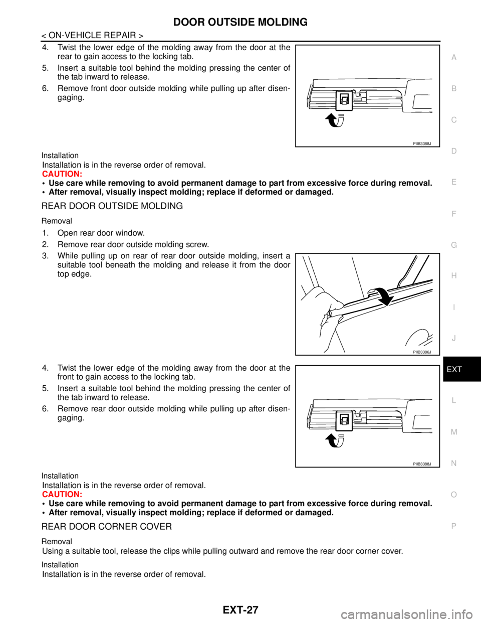
4. Twist the lower edge of the molding away from the door at the
rear to gain access to the locking tab.
5. Insert a suitable tool behind the molding pressing the center of
the tab inward to release.
6. Remove front door outside molding while pulling up after disen-
gaging.
Installation
Installation is in the reverse order of removal.
CAUTION:
Use care while removing to avoid permanent damage to part from excessive force during removal.
After removal, visually inspect molding; replace if deformed or damaged.
REAR DOOR OUTSIDE MOLDING
Removal
1. Open rear door window.
2. Remove rear door outside molding screw.
3. While pulling up on rear of rear door outside molding, insert a
suitable tool beneath the molding and release it from the door
top edge.
4. Twist the lower edge of the molding away from the door at the
front to gain access to the locking tab.
5. Insert a suitable tool behind the molding pressing the center of
the tab inward to release.
6. Remove rear door outside molding while pulling up after disen-
gaging.
Installation
Installation is in the reverse order of removal.
CAUTION:
Use care while removing to avoid permanent damage to part from excessive force during removal.
After removal, visually inspect molding; replace if deformed or damaged.
REAR DOOR CORNER COVER
Removal
Using a suitable tool, release the clips while pulling outward and remove the rear door corner cover.
Installation
Installation is in the reverse order of removal.
PIIB3388J
PIIB3386J
PIIB3388J
Page 3132 of 5883
EXT-28
< ON-VEHICLE REPAIR >
CENTER MUD GUARD
CENTER MUD GUARD
Removal and InstallationINFOID:0000000001568937
REMOVAL
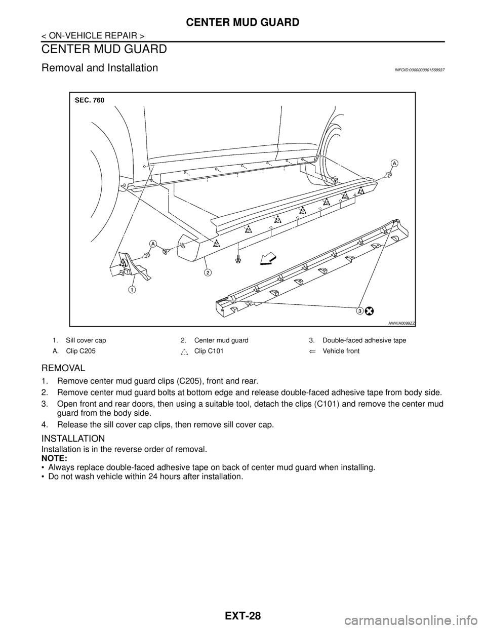
1. Remove center mud guard clips (C205), front and rear.
2. Remove center mud guard bolts at bottom edge and release double-faced adhesive tape from body side.
3. Open front and rear doors, then using a suitable tool, detach the clips (C101) and remove the center mud
guard from the body side.
4. Release the sill cover cap clips, then remove sill cover cap.
INSTALLATION
Installation is in the reverse order of removal.
NOTE:
Always replace double-faced adhesive tape on back of center mud guard when installing.
Do not wash vehicle within 24 hours after installation.
1. Sill cover cap 2. Center mud guard 3. Double-faced adhesive tape
A. Clip C205 Clip C101⇐Vehicle front
AWKIA0099ZZ
Page 3133 of 5883
TRUNK LID FINISHER
EXT-29
< ON-VEHICLE REPAIR >
C
D
E
F
G
H
I
J
L
MA
B
EXT
N
O
P
TRUNK LID FINISHER
Removal and InstallationINFOID:0000000001568938
REMOVAL
1. Disconnect the negative and positive battery terminals.
2. Open trunk lid, remove the trunk lid finisher inner. Refer to INT-17, "
Removal and Installation".
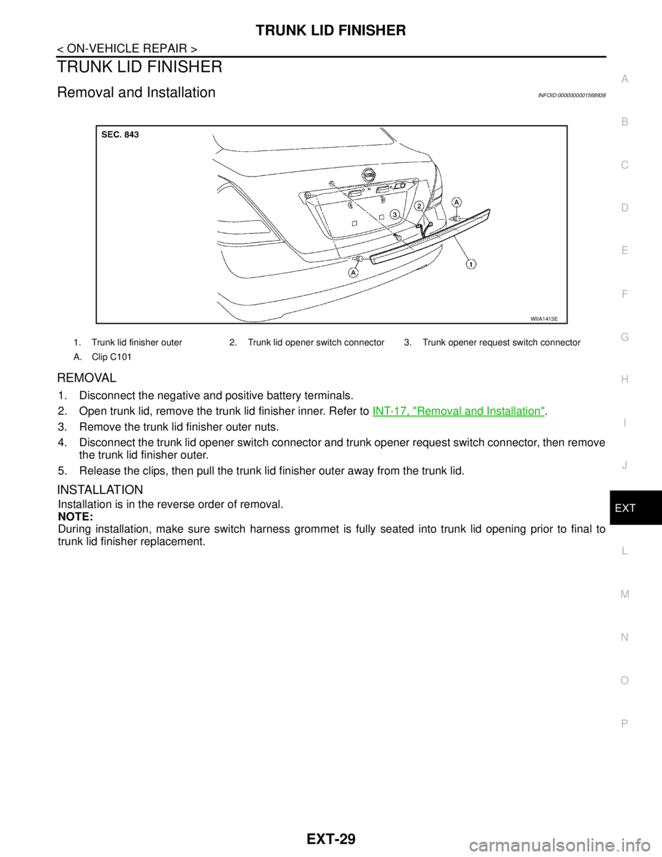
3. Remove the trunk lid finisher outer nuts.
4. Disconnect the trunk lid opener switch connector and trunk opener request switch connector, then remove
the trunk lid finisher outer.
5. Release the clips, then pull the trunk lid finisher outer away from the trunk lid.
INSTALLATION
Installation is in the reverse order of removal.
NOTE:
During installation, make sure switch harness grommet is fully seated into trunk lid opening prior to final to
trunk lid finisher replacement.
1. Trunk lid finisher outer 2. Trunk lid opener switch connector 3. Trunk opener request switch connector
A. Clip C101
WIIA1413E
Page 3134 of 5883
EXT-30
< ON-VEHICLE REPAIR >
REAR AIR SPOILER
REAR AIR SPOILER
Removal and InstallationINFOID:0000000001568939
Removal
1. Disconnect the negative and positive battery cables.
2. Remove back door finisher upper. Refer to INT-35, "
Removal and Installation".
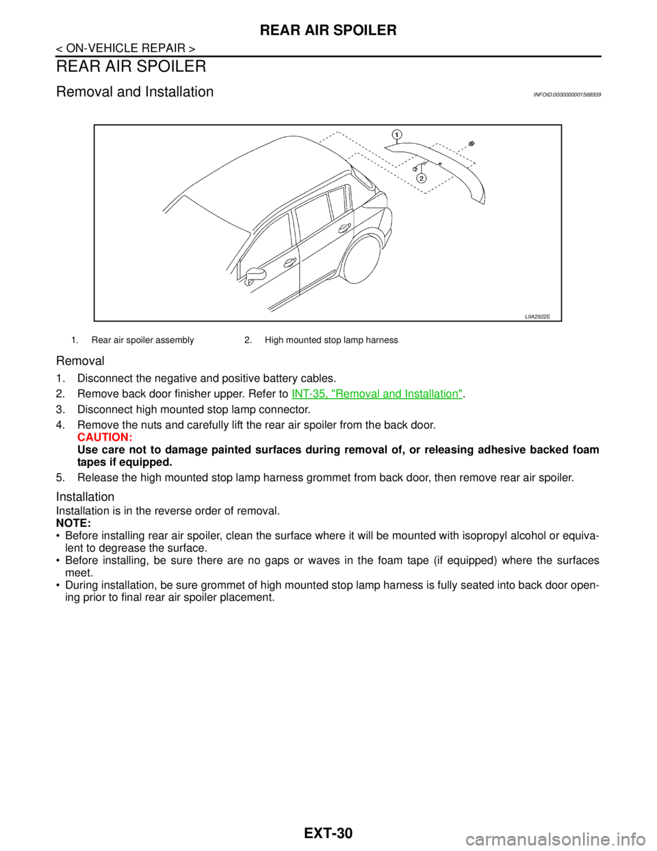
3. Disconnect high mounted stop lamp connector.
4. Remove the nuts and carefully lift the rear air spoiler from the back door.
CAUTION:
Use care not to damage painted surfaces during removal of, or releasing adhesive backed foam
tapes if equipped.
5. Release the high mounted stop lamp harness grommet from back door, then remove rear air spoiler.
Installation
Installation is in the reverse order of removal.
NOTE:
Before installing rear air spoiler, clean the surface where it will be mounted with isopropyl alcohol or equiva-
lent to degrease the surface.
Before installing, be sure there are no gaps or waves in the foam tape (if equipped) where the surfaces
meet.
During installation, be sure grommet of high mounted stop lamp harness is fully seated into back door open-
ing prior to final rear air spoiler placement.
1. Rear air spoiler assembly 2. High mounted stop lamp harness
LIIA2922E
Page 3135 of 5883
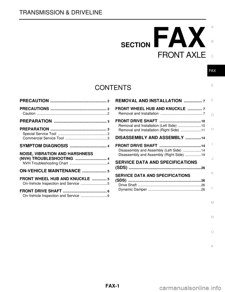
FAX-1
TRANSMISSION & DRIVELINE
C
E
F
G
H
I
J
K
L
M
SECTION FA X
A
B
FA X
N
O
P
CONTENTS
FRONT AXLE
PRECAUTION ...............................................2
PRECAUTIONS ...................................................2
Caution ......................................................................2
PREPARATION ............................................3
PREPARATION ...................................................3
Special Service Tool .................................................3
Commercial Service Tool ..........................................3
SYMPTOM DIAGNOSIS ...............................4
NOISE, VIBRATION AND HARSHNESS
(NVH) TROUBLESHOOTING .............................
4
NVH Troubleshooting Chart ......................................4
ON-VEHICLE MAINTENANCE .....................5
FRONT WHEEL HUB AND KNUCKLE ..............5
On-Vehicle Inspection and Service ...........................5
FRONT DRIVE SHAFT ........................................6
On-Vehicle Inspection and Service ...........................6
REMOVAL AND INSTALLATION ................7
FRONT WHEEL HUB AND KNUCKLE .............7
Removal and Installation ..........................................7
FRONT DRIVE SHAFT .....................................10
Removal and Installation (Left Side) ........................10
Removal and Installation (Right Side) .....................11
DISASSEMBLY AND ASSEMBLY ..............14
FRONT DRIVE SHAFT .....................................14
Disassembly and Assembly (Left Side) ...................14
Disassembly and Assembly (Right Side) .................19
SERVICE DATA AND SPECIFICATIONS
(SDS) ............................................................
26
SERVICE DATA AND SPECIFICATIONS
(SDS) .................................................................
26
Drive Shaft ...............................................................26
Dynamic Damper .....................................................26
Page 3136 of 5883
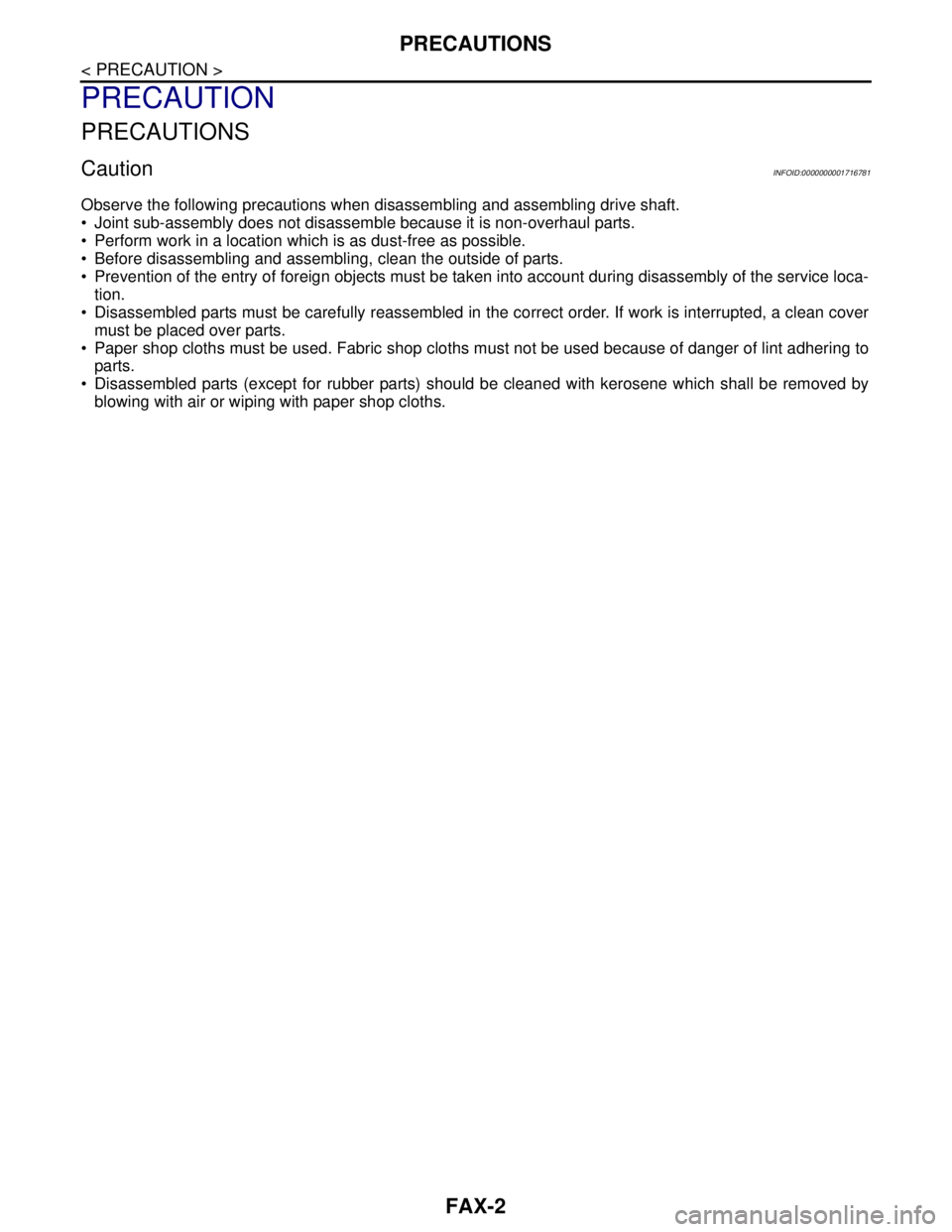
FAX-2
< PRECAUTION >
PRECAUTIONS
PRECAUTION
PRECAUTIONS
CautionINFOID:0000000001716781
Observe the following precautions when disassembling and assembling drive shaft.
• Joint sub-assembly does not disassemble because it is non-overhaul parts.
Perform work in a location which is as dust-free as possible.
Before disassembling and assembling, clean the outside of parts.
Prevention of the entry of foreign objects must be taken into account during disassembly of the service loca-
tion.
Disassembled parts must be carefully reassembled in the correct order. If work is interrupted, a clean cover
must be placed over parts.
Paper shop cloths must be used. Fabric shop cloths must not be used because of danger of lint adhering to
parts.
Disassembled parts (except for rubber parts) should be cleaned with kerosene which shall be removed by
blowing with air or wiping with paper shop cloths.
Page 3137 of 5883
PREPARATION
FAX-3
< PREPARATION >
C
E
F
G
H
I
J
K
L
MA
B
FA X
N
O
P
PREPARATION
PREPARATION
Special Service ToolINFOID:0000000001716782
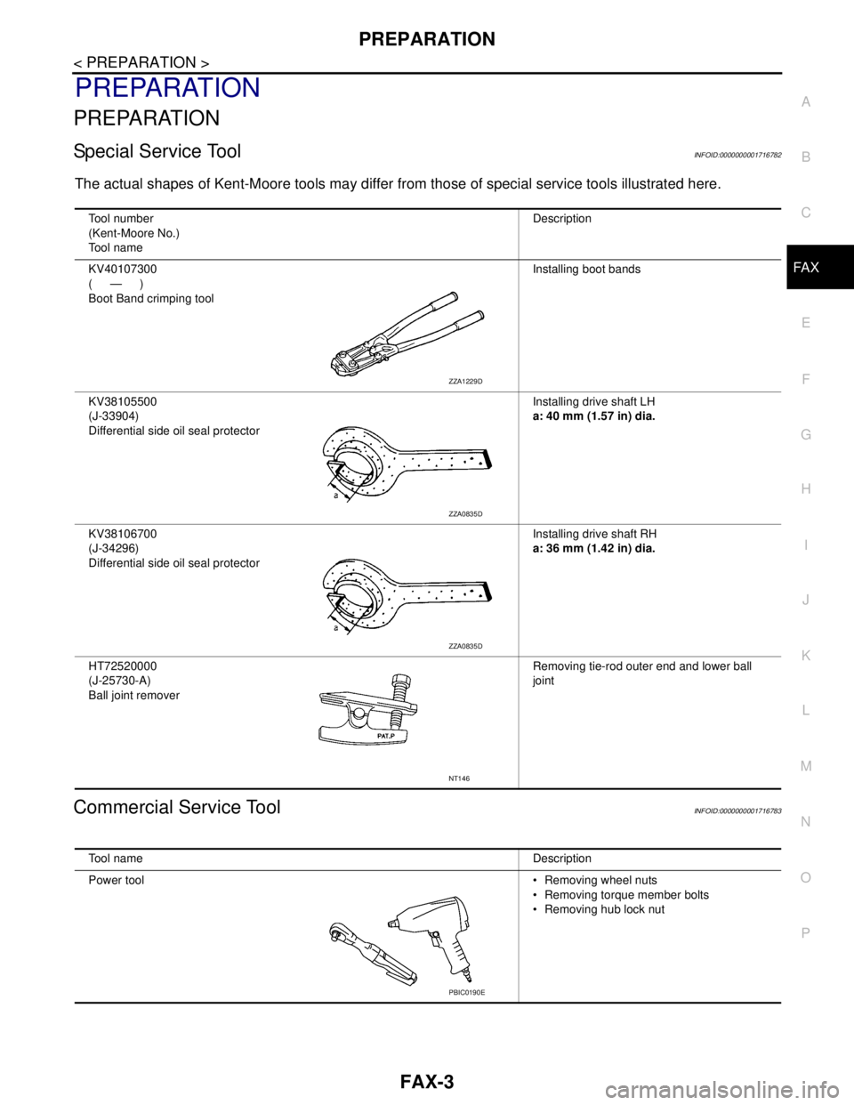
The actual shapes of Kent-Moore tools may differ from those of special service tools illustrated here.
Commercial Service ToolINFOID:0000000001716783
Tool number
(Kent-Moore No.)
Tool nameDescription
KV40107300
(—)
Boot Band crimping toolInstalling boot bands
KV38105500
(J-33904)
Differential side oil seal protectorInstalling drive shaft LH
a: 40 mm (1.57 in) dia.
KV38106700
(J-34296)
Differential side oil seal protectorInstalling drive shaft RH
a: 36 mm (1.42 in) dia.
HT72520000
(J-25730-A)
Ball joint removerRemoving tie-rod outer end and lower ball
joint
ZZA1229D
ZZA0835D
ZZA0835D
NT146
Tool nameDescription
Power tool Removing wheel nuts
Removing torque member bolts
Removing hub lock nut
PBIC0190E
Page 3138 of 5883
FAX-4
< SYMPTOM DIAGNOSIS >
NOISE, VIBRATION AND HARSHNESS (NVH) TROUBLESHOOTING
SYMPTOM DIAGNOSIS
NOISE, VIBRATION AND HARSHNESS (NVH) TROUBLESHOOTING
NVH Troubleshooting ChartINFOID:0000000001716784
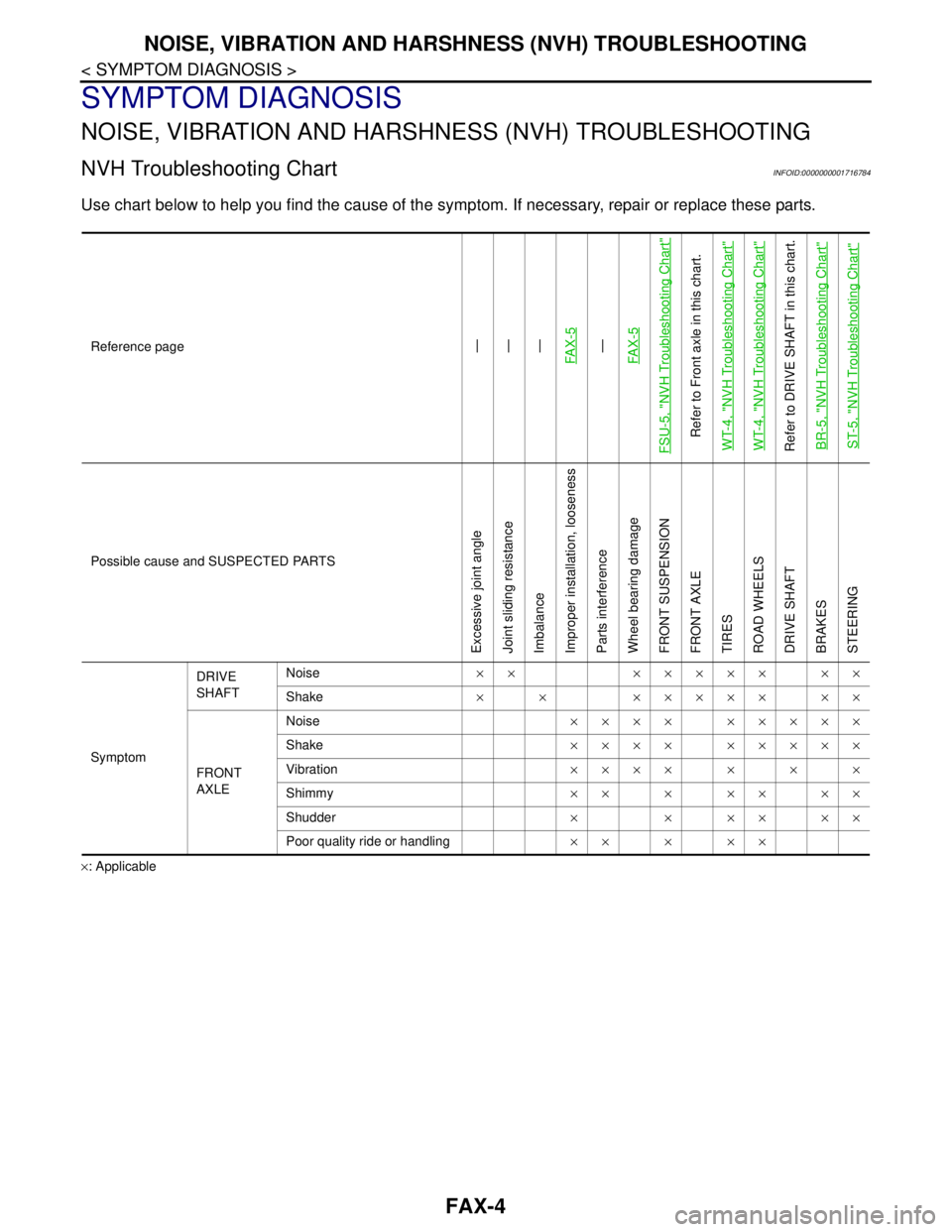
Use chart below to help you find the cause of the symptom. If necessary, repair or replace these parts.
×: ApplicableReference page
—
—
—
FA X - 5—
FA X - 5
FSU-5, "
NVH Troubleshooting Chart
"
Refer to Front axle in this chart.
WT-4, "
NVH Troubleshooting Chart
"
WT-4, "
NVH Troubleshooting Chart
"
Refer to DRIVE SHAFT in this chart.
BR-5, "
NVH Troubleshooting Chart
"
ST-5, "
NVH Troubleshooting Chart
"
Possible cause and SUSPECTED PARTS
Excessive joint angle
Joint sliding resistance
Imbalance
Improper installation, looseness
Parts interference
Wheel bearing damage
FRONT SUSPENSION
FRONT AXLE
TIRES
ROAD WHEELS
DRIVE SHAFT
BRAKES
STEERING
SymptomDRIVE
SHAFTNoise×× ××××× ××
Shake× × ××××× ××
FRONT
AXLENoise×××× ×××××
Shake×××× ×××××
Vibration×××××××
Shimmy×××××××
Shudder× × ×× ××
Poor quality ride or handling×××××
Page 3139 of 5883
FRONT WHEEL HUB AND KNUCKLE
FAX-5
< ON-VEHICLE MAINTENANCE >
C
E
F
G
H
I
J
K
L
MA
B
FA X
N
O
P
ON-VEHICLE MAINTENANCE
FRONT WHEEL HUB AND KNUCKLE
On-Vehicle Inspection and ServiceINFOID:0000000001716786
Check the axle and suspension parts for excessive play, wear, or damage.
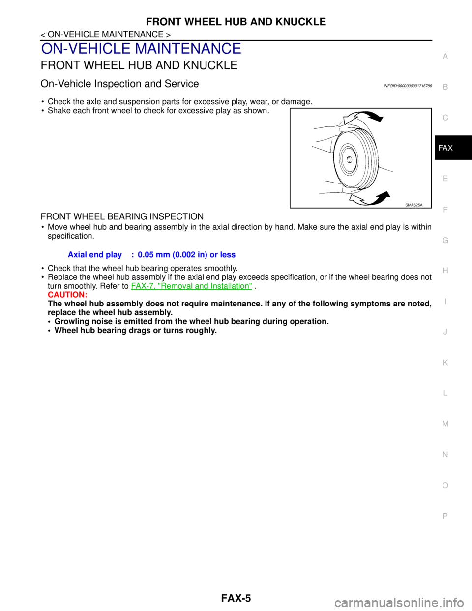
Shake each front wheel to check for excessive play as shown.
FRONT WHEEL BEARING INSPECTION
Move wheel hub and bearing assembly in the axial direction by hand. Make sure the axial end play is within
specification.
Check that the wheel hub bearing operates smoothly.
Replace the wheel hub assembly if the axial end play exceeds specification, or if the wheel bearing does not
turn smoothly. Refer to FAX-7, "
Removal and Installation" .
CAUTION:
The wheel hub assembly does not require maintenance. If any of the following symptoms are noted,
replace the wheel hub assembly.
• Growling noise is emitted from the wheel hub bearing during operation.
Wheel hub bearing drags or turns roughly.
SMA525A
Axial end play : 0.05 mm (0.002 in) or less
Page 3140 of 5883
FAX-6
< ON-VEHICLE MAINTENANCE >
FRONT DRIVE SHAFT
FRONT DRIVE SHAFT
On-Vehicle Inspection and ServiceINFOID:0000000001716790
Check drive shaft mounting point and joint for looseness and other damage.
Check boot for cracks and other damage.
Replace or repair components as necessary. Refer to FAX-10, "
Removal and Installation (Left Side)" , FA X - 11 ,
"Removal and Installation (Right Side)" , FAX-14, "Disassembly and Assembly (Left Side)" or FAX-19, "Disas-
sembly and Assembly (Right Side)" .
CAUTION:
Replace entire drive shaft assembly when noise or vibration occur from drive shaft.