NISSAN X-TRAIL 2003 Electronic Repair Manual
Manufacturer: NISSAN, Model Year: 2003, Model line: X-TRAIL, Model: NISSAN X-TRAIL 2003Pages: 3066, PDF Size: 51.47 MB
Page 2831 of 3066
SIDE OIL SEAL
RFD-9
C
E
F
G
H
I
J
K
L
MA
B
RFD
SIDE OIL SEALPFP:38343
Removal and InstallationEDS000DF
REMOVAL
1. Remove drive shaft. Refer toRAX-9, "Removal".
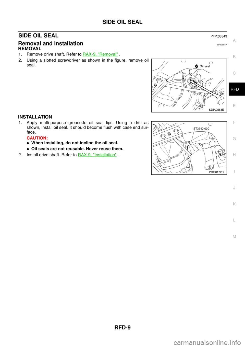
2. Using a slotted screwdriver as shown in the figure, remove oil
seal.
INSTALLATION
1. Apply multi-purpose grease.to oil seal lips. Using a drift as
shown, install oil seal. It should become flush with case end sur-
face.
CAUTION:
lWhen installing, do not incline the oil seal.
lOil seals are not reusable. Never reuse them.
2. Install drive shaft. Refer toRAX-9, "
Installation".
SDIA0568E
PDG0172D
Page 2832 of 3066
RFD-10
REAR COVER GASKET
REAR COVER GASKET
PFP:38320
ReplacementEDS0005D
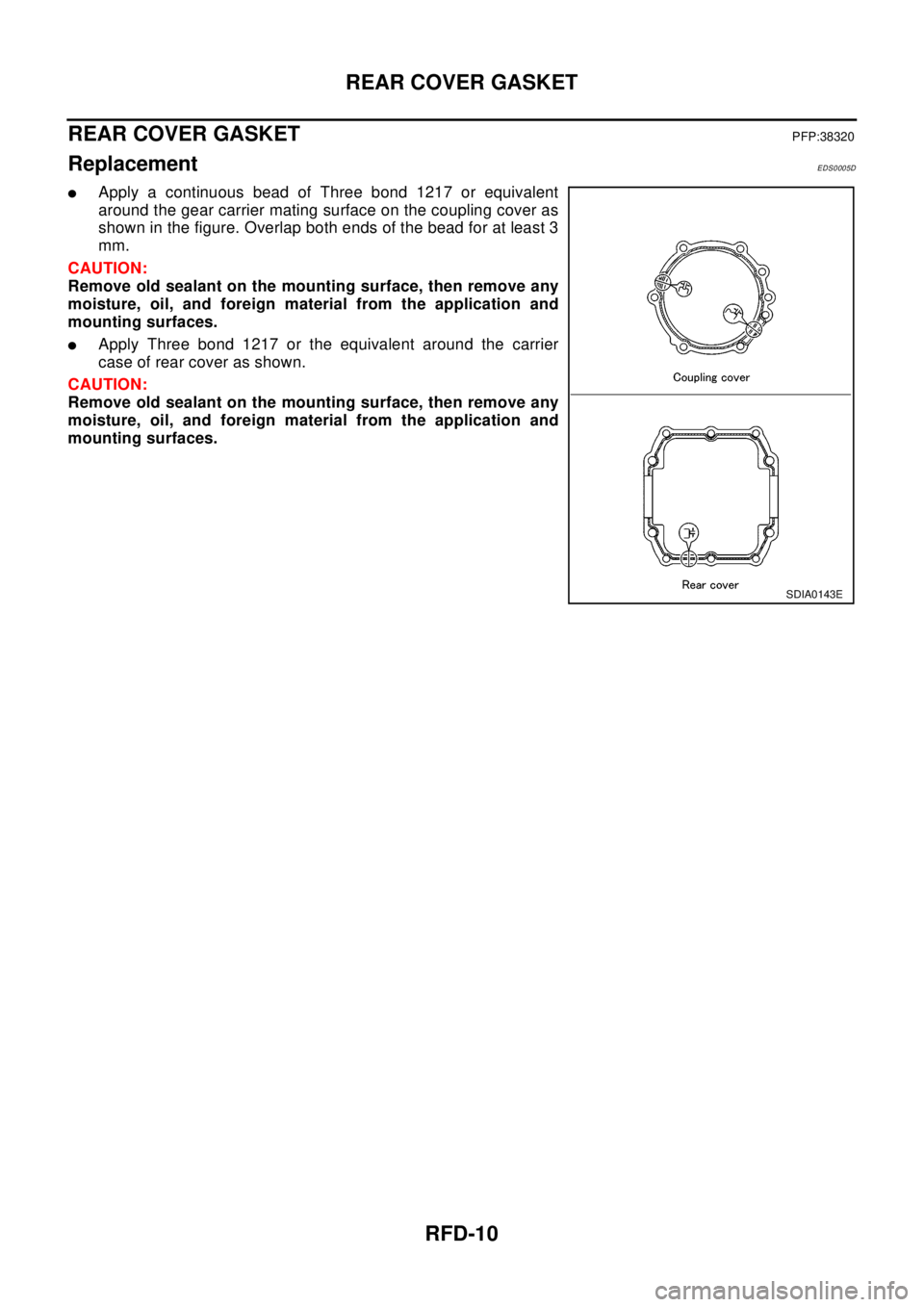
lApply a continuous bead of Three bond 1217 or equivalent
around the gear carrier mating surface on the coupling cover as
shown in the figure. Overlap both ends of the bead for at least 3
mm.
CAUTION:
Remove old sealant on the mounting surface, then remove any
moisture, oil, and foreign material from the application and
mounting surfaces.
lApply Three bond 1217 or the equivalent around the carrier
case of rear cover as shown.
CAUTION:
Remove old sealant on the mounting surface, then remove any
moisture, oil, and foreign material from the application and
mounting surfaces.
SDIA0143E
Page 2833 of 3066
REAR FINAL DRIVE ASSEMBLY
RFD-11
C
E
F
G
H
I
J
K
L
MA
B
RFD
REAR FINAL DRIVE ASSEMBLYPFP:38300
Removal and InstallationEDS000DG
REMOVAL
1. Remove rear suspension assembly. Refer toRSU-5, "REAR SUSPENSION ASSEMBLY".
2. Remove propeller shaft. Refer toPR-3, "
Removal and Installation".
3. Remove drive shaft. Refer toRAX-9, "
REAR DRIVE SHAFT".
4. Remove ABS sensor connector. With 4WD/ABS refer toBRC-50, "
Removal and Installation", With ESP/
TCS/ABS refer toBRC-120, "
Removal and Installation"
5. Remove air breather hose (for electronically controlled coupling and for rear final drive). Refer toRFD-12,
"Electronically Controlled Coupling Breather Hose",RFD-13, "Rear Final Drive Breather Hose".
6. Remove brake tube (and bleed air in the brake piping). Refer toBR-12, "
Removal and Installation of Rear
Brake Piping and Brake Hose".
INSTALLATION
Install in the reverse order of the removal.
CAUTION:
lAfter installation, bleed air in the brake system and check oil level in the final drive.
lKeep the air breather hose to exhaust tube clearance for at least 40 mm (1.57 in).
SDIA0108E
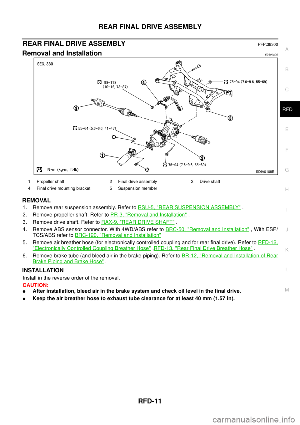
1 Propeller shaft 2 Final drive assembly 3 Drive shaft
4 Final drive mounting bracket 5 Suspension member
Page 2834 of 3066
RFD-12
REAR FINAL DRIVE ASSEMBLY
Electronically Controlled Coupling Breather Hose
EDS0005F
CAUTION:
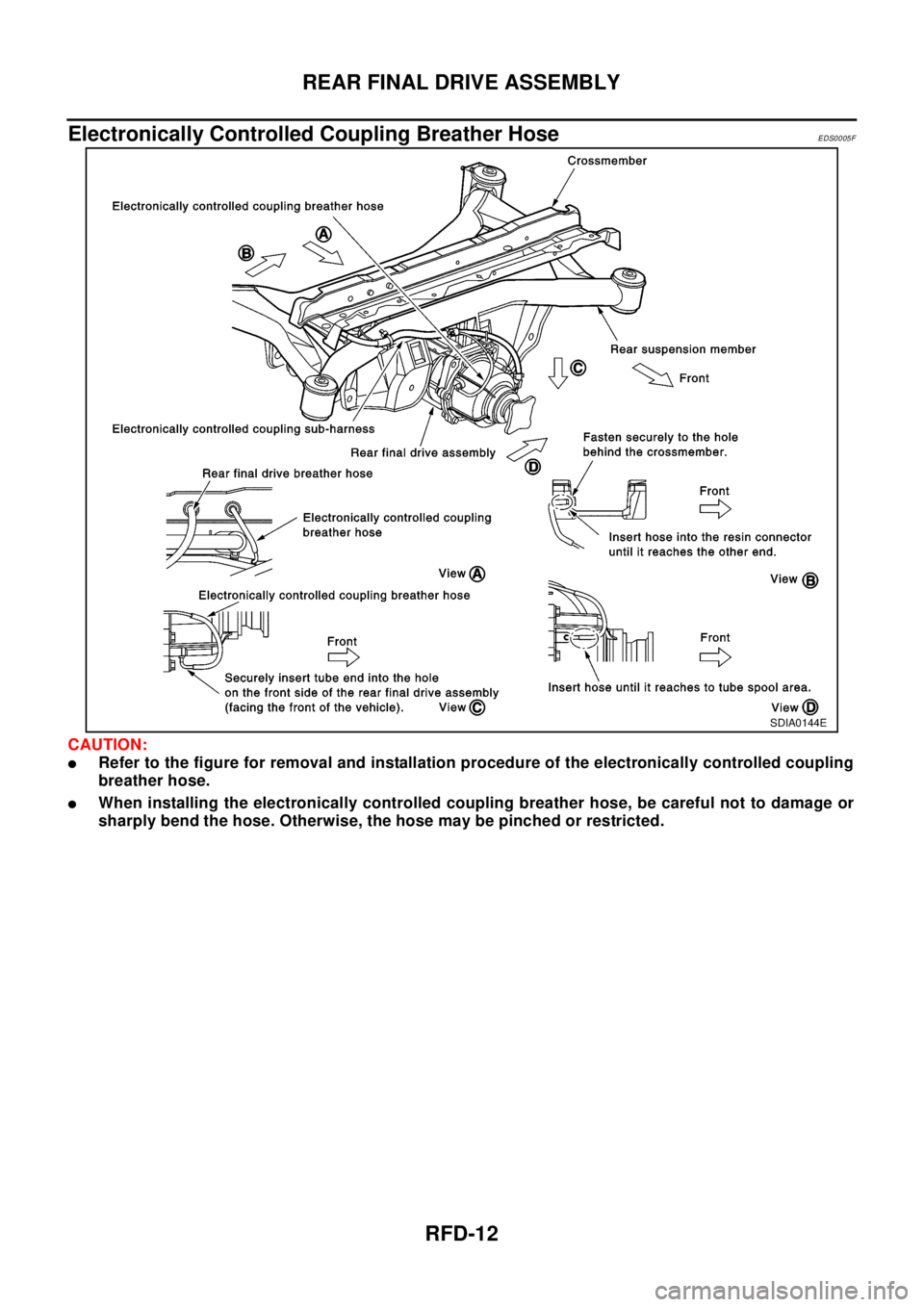
lRefer to the figure for removal and installation procedure of the electronically controlled coupling
breather hose.
lWhen installing the electronically controlled coupling breather hose, be careful not to damage or
sharply bend the hose. Otherwise, the hose may be pinched or restricted.
SDIA0144E
Page 2835 of 3066
REAR FINAL DRIVE ASSEMBLY
RFD-13
C
E
F
G
H
I
J
K
L
MA
B
RFD
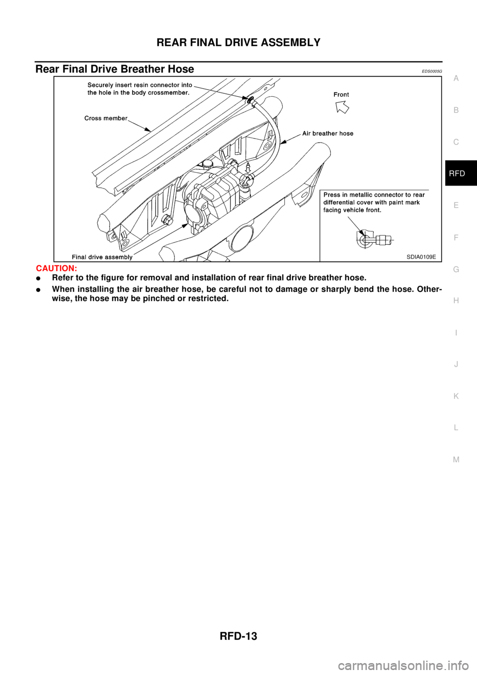
Rear Final Drive Breather HoseEDS0005G
CAUTION:
lRefer to the figure for removal and installation of rear final drive breather hose.
lWhen installing the air breather hose, be careful not to damage or sharply bend the hose. Other-
wise, the hose may be pinched or restricted.
SDIA0109E
Page 2836 of 3066
RFD-14
REAR FINAL DRIVE ASSEMBLY
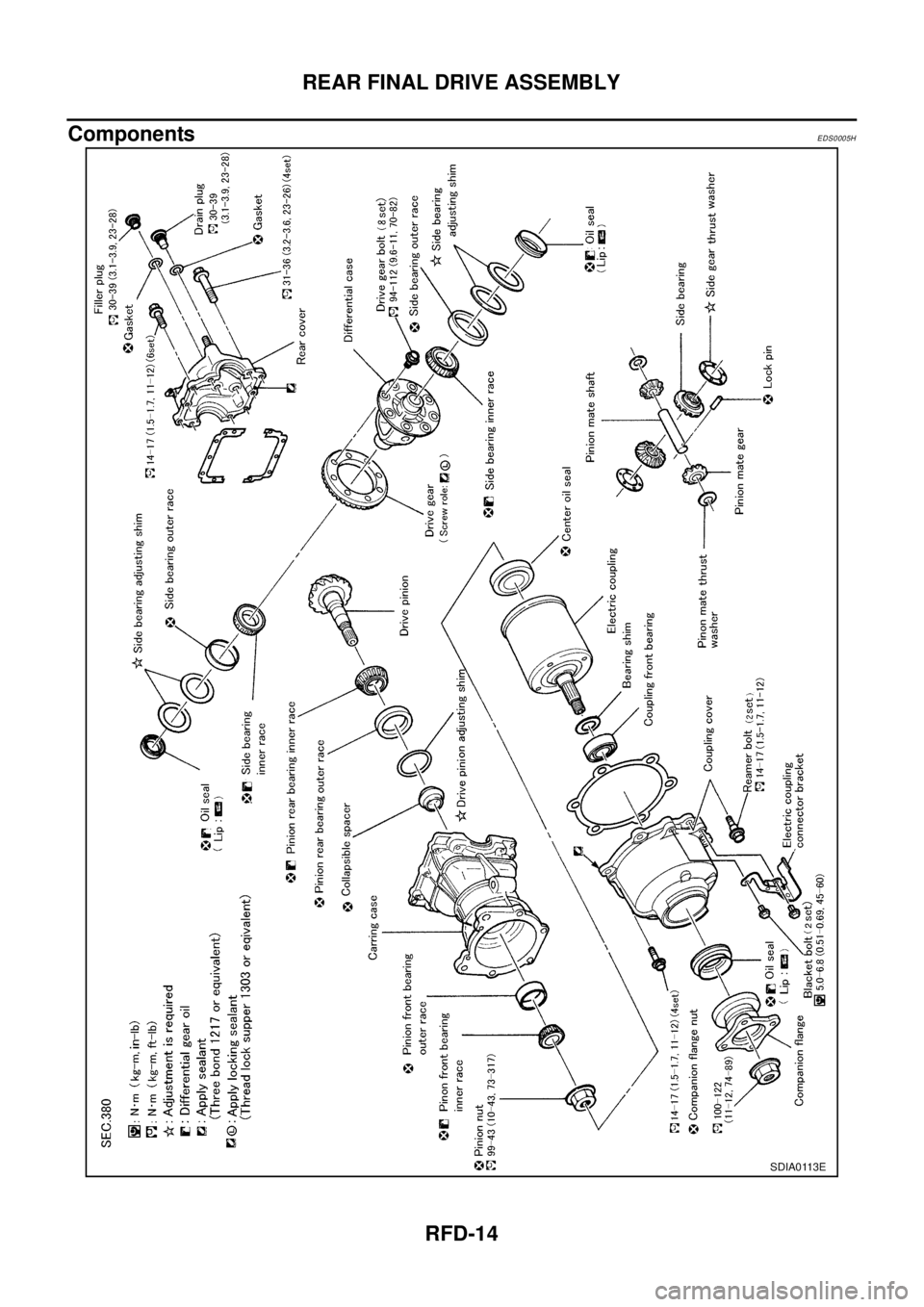
Components
EDS0005H
SDIA0113E
Page 2837 of 3066
REAR FINAL DRIVE ASSEMBLY
RFD-15
C
E
F
G
H
I
J
K
L
MA
B
RFD
Inspection Before DisassemblyEDS0005I
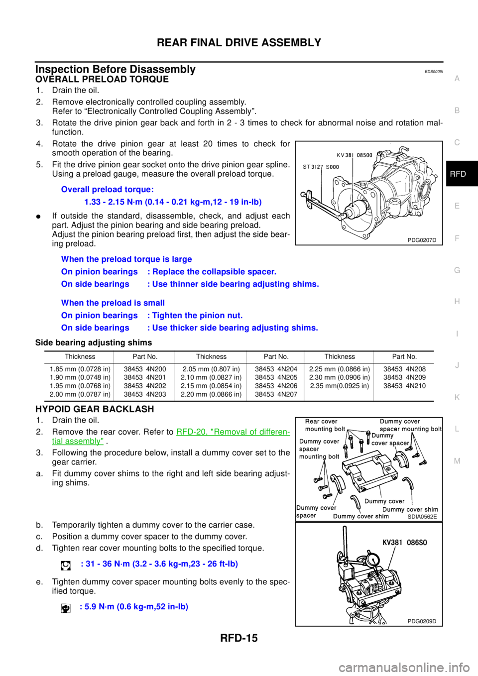
OVERALL PRELOAD TORQUE
1. Drain the oil.
2. Remove electronically controlled coupling assembly.
Refer to “Electronically Controlled Coupling Assembly”.
3. Rotate the drive pinion gear back and forth in 2 - 3 times to check for abnormal noise and rotation mal-
function.
4. Rotate the drive pinion gear at least 20 times to check for
smooth operation of the bearing.
5. Fit the drive pinion gear socket onto the drive pinion gear spline.
Using a preload gauge, measure the overall preload torque.
lIf outside the standard, disassemble, check, and adjust each
part. Adjust the pinion bearing and side bearing preload.
Adjust the pinion bearing preload first, then adjust the side bear-
ing preload.
Side bearing adjusting shims
HYPOID GEAR BACKLASH
1. Drain the oil.
2. Remove the rear cover. Refer toRFD-20, "
Removal of differen-
tial assembly".
3. Following the procedure below, install a dummy cover set to the
gear carrier.
a. Fit dummy cover shims to the right and left side bearing adjust-
ing shims.
b. Temporarily tighten a dummy cover to the carrier case.
c. Position a dummy cover spacer to the dummy cover.
d. Tighten rear cover mounting bolts to the specified torque.
e. Tighten dummy cover spacer mounting bolts evenly to the spec-
ified torque.Overall preload torque:
1.33 - 2.15 N·m (0.14 - 0.21 kg-m,12 - 19 in-lb)
When the preload torque is large
On pinion bearings : Replace the collapsible spacer.
On side bearings : Use thinner side bearing adjusting shims.
When the preload is small
On pinion bearings : Tighten the pinion nut.
On side bearings : Use thicker side bearing adjusting shims.
PDG0207D
Thickness Part No. Thickness Part No. Thickness Part No.
1.85 mm (0.0728 in)
1.90 mm (0.0748 in)
1.95 mm (0.0768 in)
2.00 mm (0.0787 in)38453 4N200
38453 4N201
38453 4N202
38453 4N2032.05 mm (0.807 in)
2.10 mm (0.0827 in)
2.15 mm (0.0854 in)
2.20 mm (0.0866 in)38453 4N204
38453 4N205
38453 4N206
38453 4N2072.25 mm (0.0866 in)
2.30 mm (0.0906 in)
2.35 mm(0.0925 in)38453 4N208
38453 4N209
38453 4N210
: 31 - 36 N·m (3.2 - 3.6 kg-m,23 - 26 ft-lb)
: 5.9 N·m (0.6 kg-m,52 in-lb)
SDIA0562E
PDG0209D
Page 2838 of 3066
RFD-16
REAR FINAL DRIVE ASSEMBLY
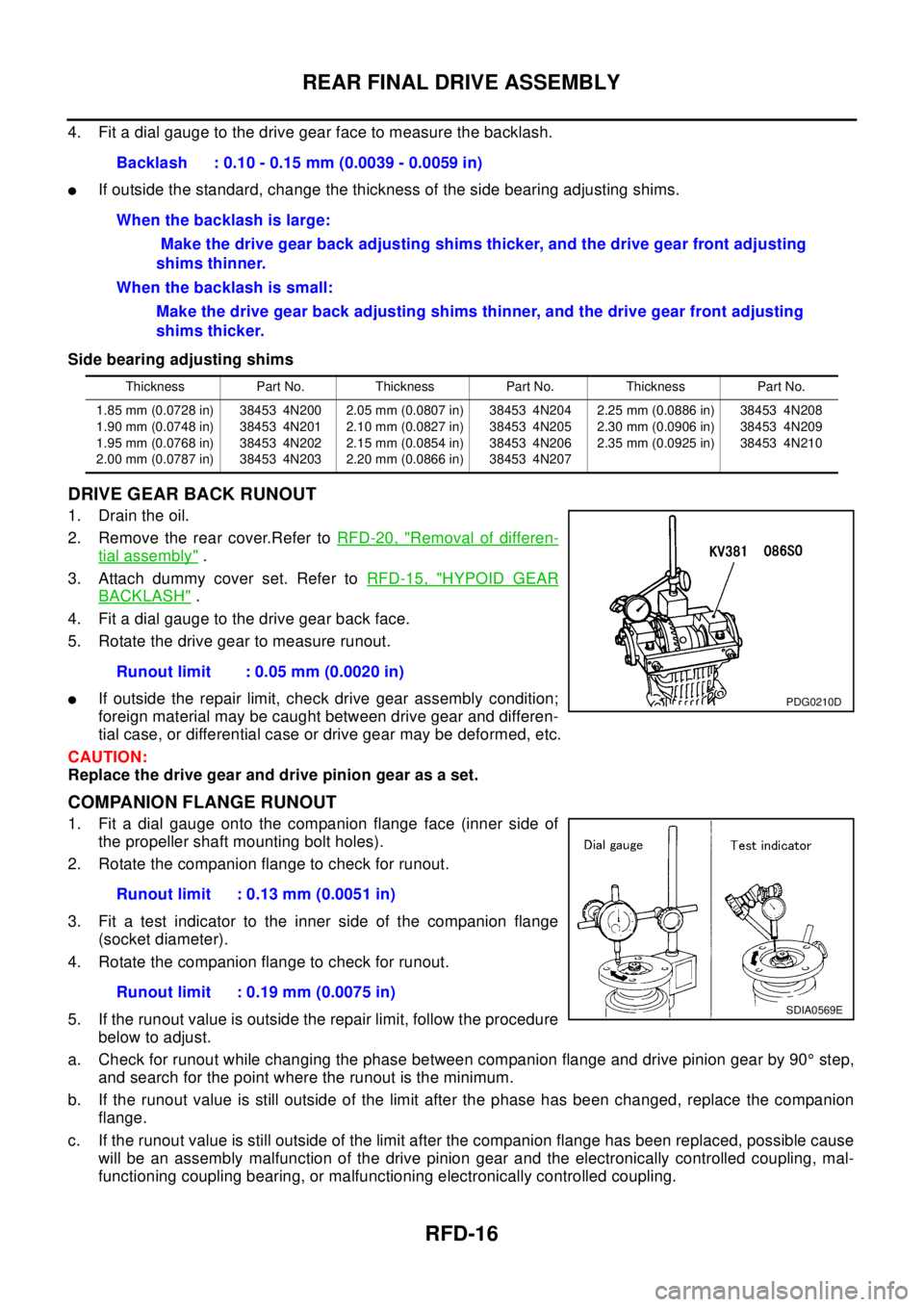
4. Fit a dial gauge to the drive gear face to measure the backlash.
lIf outside the standard, change the thickness of the side bearing adjusting shims.
Side bearing adjusting shims
DRIVE GEAR BACK RUNOUT
1. Drain the oil.
2. Remove the rear cover.Refer toRFD-20, "
Removal of differen-
tial assembly".
3. Attach dummy cover set. Refer toRFD-15, "
HYPOID GEAR
BACKLASH".
4. Fit a dial gauge to the drive gear back face.
5. Rotate the drive gear to measure runout.
lIf outside the repair limit, check drive gear assembly condition;
foreign material may be caught between drive gear and differen-
tial case, or differential case or drive gear may be deformed, etc.
CAUTION:
Replace the drive gear and drive pinion gear as a set.
COMPANION FLANGE RUNOUT
1. Fit a dial gauge onto the companion flange face (inner side of
the propeller shaft mounting bolt holes).
2. Rotate the companion flange to check for runout.
3. Fit a test indicator to the inner side of the companion flange
(socket diameter).
4. Rotate the companion flange to check for runout.
5. If the runout value is outside the repair limit, follow the procedure
below to adjust.
a. Check for runout while changing the phase between companion flange and drive pinion gear by 90°step,
and search for the point where the runout is the minimum.
b. If the runout value is still outside of the limit after the phase has been changed, replace the companion
flange.
c. If the runout value is still outside of the limit after the companion flange has been replaced, possible cause
will be an assembly malfunction of the drive pinion gear and the electronically controlled coupling, mal-
functioning coupling bearing, or malfunctioning electronically controlled coupling.Backlash : 0.10 - 0.15 mm (0.0039 - 0.0059 in)
When the backlash is large:
Make the drive gear back adjusting shims thicker, and the drive gear front adjusting
shims thinner.
When the backlash is small:
Make the drive gear back adjusting shims thinner, and the drive gear front adjusting
shims thicker.
Thickness Part No. Thickness Part No. Thickness Part No.
1.85 mm (0.0728 in)
1.90 mm (0.0748 in)
1.95 mm (0.0768 in)
2.00 mm (0.0787 in)38453 4N200
38453 4N201
38453 4N202
38453 4N2032.05 mm (0.0807 in)
2.10 mm (0.0827 in)
2.15 mm (0.0854 in)
2.20 mm (0.0866 in)38453 4N204
38453 4N205
38453 4N206
38453 4N2072.25 mm (0.0886 in)
2.30 mm (0.0906 in)
2.35 mm (0.0925 in)38453 4N208
38453 4N209
38453 4N210
Runout limit : 0.05 mm (0.0020 in)
PDG0210D
Runout limit : 0.13 mm (0.0051 in)
Runout limit : 0.19 mm (0.0075 in)
SDIA0569E
Page 2839 of 3066
REAR FINAL DRIVE ASSEMBLY
RFD-17
C
E
F
G
H
I
J
K
L
MA
B
RFD
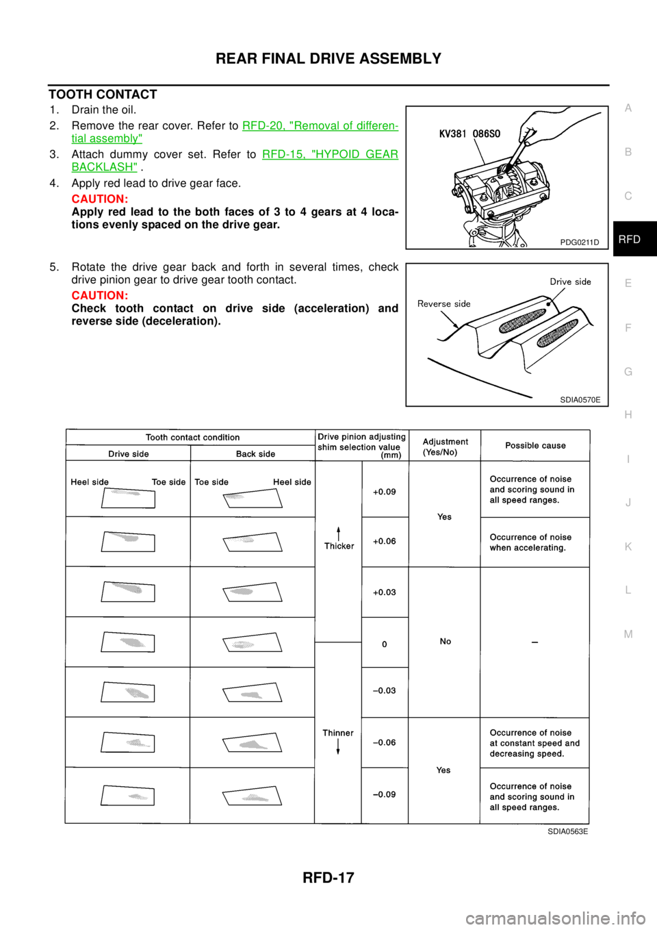
TOOTH CONTACT
1. Drain the oil.
2. Remove the rear cover. Refer toRFD-20, "
Removal of differen-
tial assembly"
3. Attach dummy cover set. Refer toRFD-15, "HYPOID GEAR
BACKLASH".
4. Apply red lead to drive gear face.
CAUTION:
Apply red lead to the both faces of 3 to 4 gears at 4 loca-
tions evenly spaced on the drive gear.
5. Rotate the drive gear back and forth in several times, check
drive pinion gear to drive gear tooth contact.
CAUTION:
Check tooth contact on drive side (acceleration) and
reverse side (deceleration).
PDG0211D
SDIA0570E
SDIA0563E
Page 2840 of 3066
RFD-18
REAR FINAL DRIVE ASSEMBLY
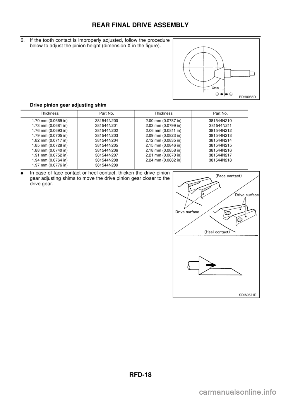
6. If the tooth contact is improperly adjusted, follow the procedure
below to adjust the pinion height (dimension X in the figure).
Drive pinion gear adjusting shim
lIn case of face contact or heel contact, thicken the drive pinion
gear adjusting shims to move the drive pinion gear closer to the
drive gear.
PDH0085D
Thickness Part No. Thickness Part No.
1.70 mm (0.0669 in)
1.73 mm (0.0681 in)
1.76 mm (0.0693 in)
1.79 mm (0.0705 in)
1.82 mm (0.0717 in)
1.85 mm (0.0728 in)
1.88 mm (0.0740 in)
1.91 mm (0.0752 in)
1.94 mm (0.0764 in)
1.97 mm (0.0776 in)381544N200
381544N201
381544N202
381544N203
381544N204
381544N205
381544N206
381544N207
381544N208
381544N2092.00 mm (0.0787 in)
2.03 mm (0.0799 in)
2.06 mm (0.0811 in)
2.09 mm (0.0823 in)
2.12 mm (0.0835 in)
2.15 mm (0.0846 in)
2.18 mm (0.0858 in)
2.21 mm (0.0870 in)
2.24 mm (0.0882 in)381544N210
381544N211
381544N212
381544N213
381544N214
381544N215
381544N216
381544N217
381544N218
SDIA0571E