NISSAN X-TRAIL 2003 Electronic Repair Manual
Manufacturer: NISSAN, Model Year: 2003, Model line: X-TRAIL, Model: NISSAN X-TRAIL 2003Pages: 3066, PDF Size: 51.47 MB
Page 2791 of 3066
POWER STEERING OIL PUMP
PS-31
C
D
E
F
H
I
J
K
L
MA
B
PS
INSPECTION AFTER DISASSEMBLY
lIf pulley is cracked or deformed, replace it.
lIf an oil leak is found around pulley shaft oil seal, replace the seal.
lIf serration on pulley or pulley shaft is deformed or worn, replace it.
ASSEMBLY
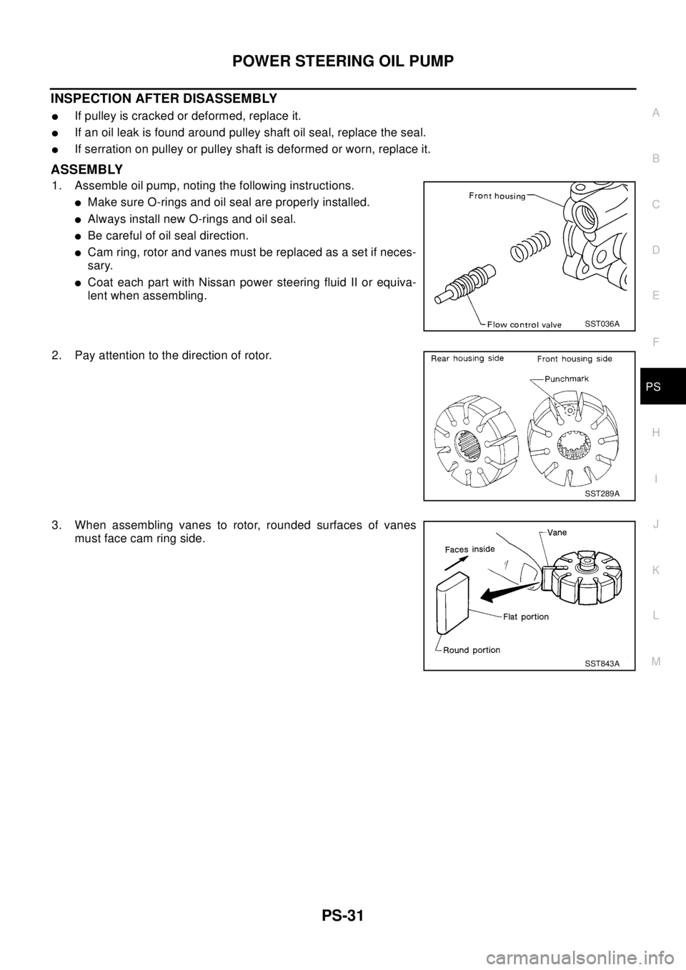
1. Assemble oil pump, noting the following instructions.
lMake sure O-rings and oil seal are properly installed.
lAlways install new O-rings and oil seal.
lBe careful of oil seal direction.
lCam ring, rotor and vanes must be replaced as a set if neces-
sary.
lCoat each part with Nissan power steering fluid II or equiva-
lent when assembling.
2. Pay attention to the direction of rotor.
3. When assembling vanes to rotor, rounded surfaces of vanes
must face cam ring side.
SST036A
SST289A
SST843A
Page 2792 of 3066
PS-32
POWER STEERING OIL PUMP
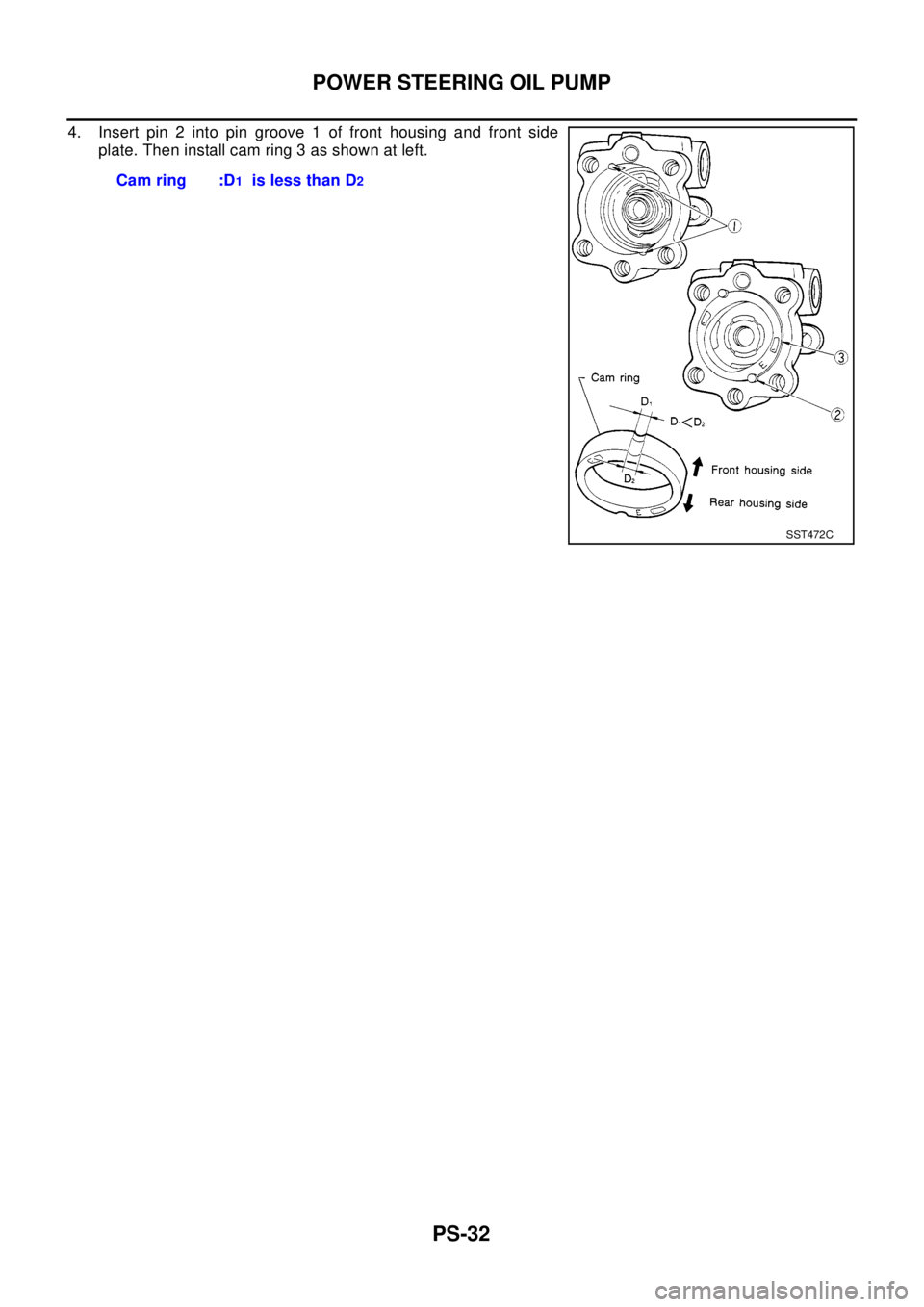
4. Insert pin 2 into pin groove 1 of front housing and front side
plate. Then install cam ring 3 as shown at left.
Cam ring :D
1is less than D2
SST472C
Page 2793 of 3066
HYDRAULIC LINE
PS-33
C
D
E
F
H
I
J
K
L
MA
B
PS
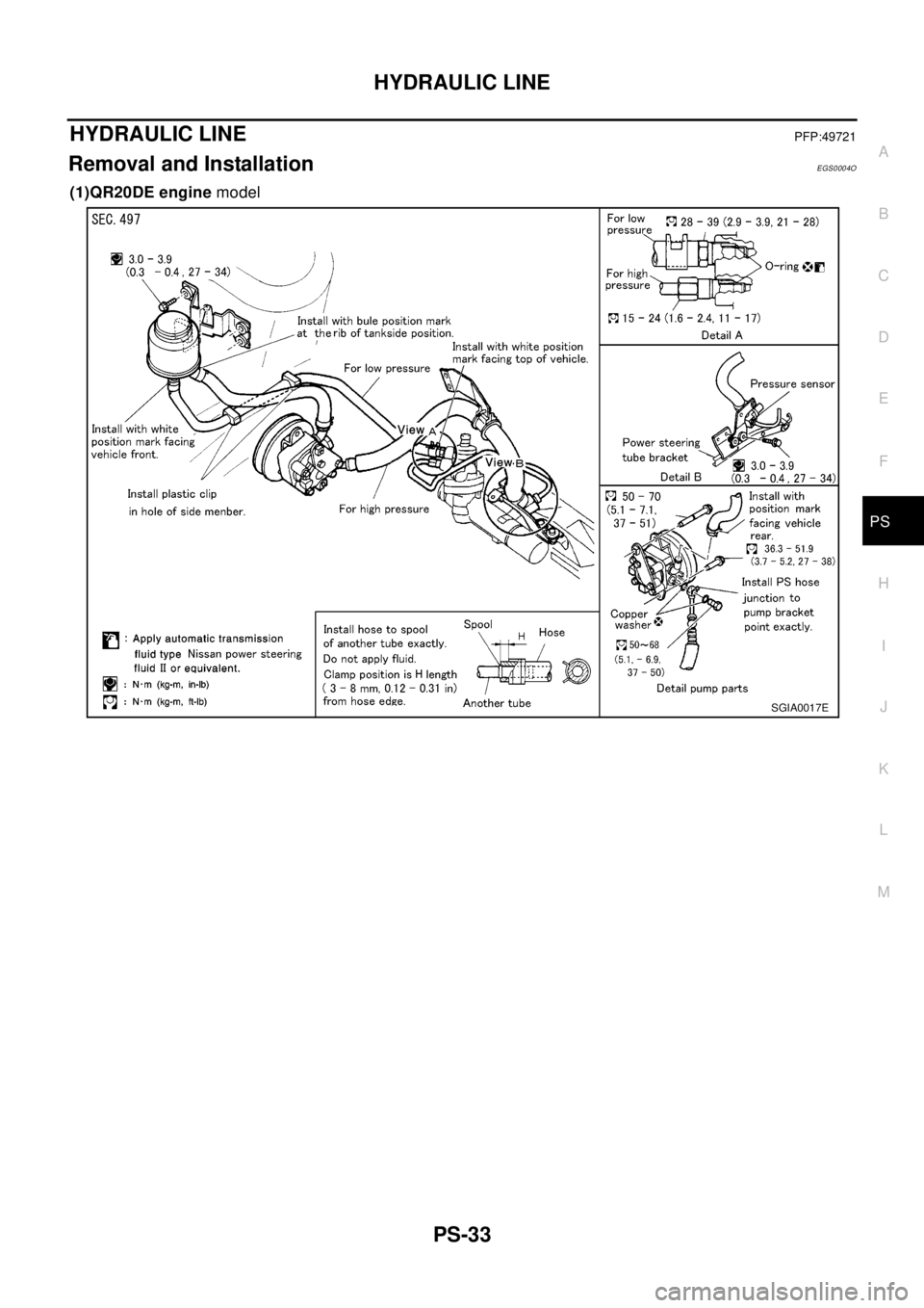
HYDRAULIC LINEPFP:49721
Removal and InstallationEGS0004O
(1)QR20DE enginemodel
SGIA0017E
Page 2794 of 3066
PS-34
HYDRAULIC LINE
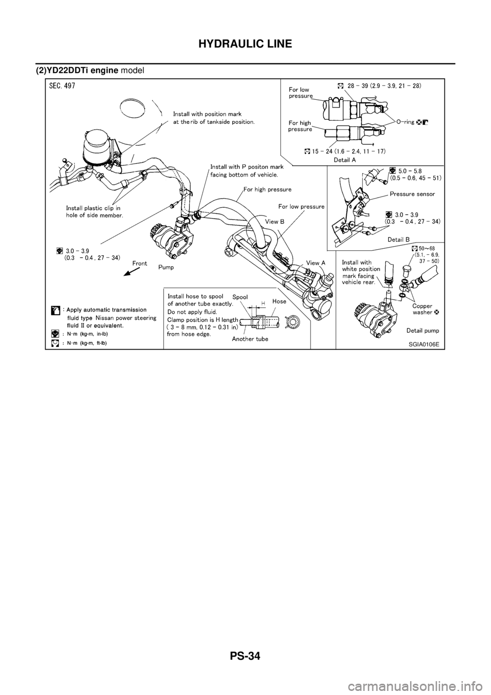
(2)YD22DDTi enginemodel
SGIA0106E
Page 2795 of 3066
SERVICE DATA AND SPECIFICATIONS (SDS)
PS-35
C
D
E
F
H
I
J
K
L
MA
B
PS
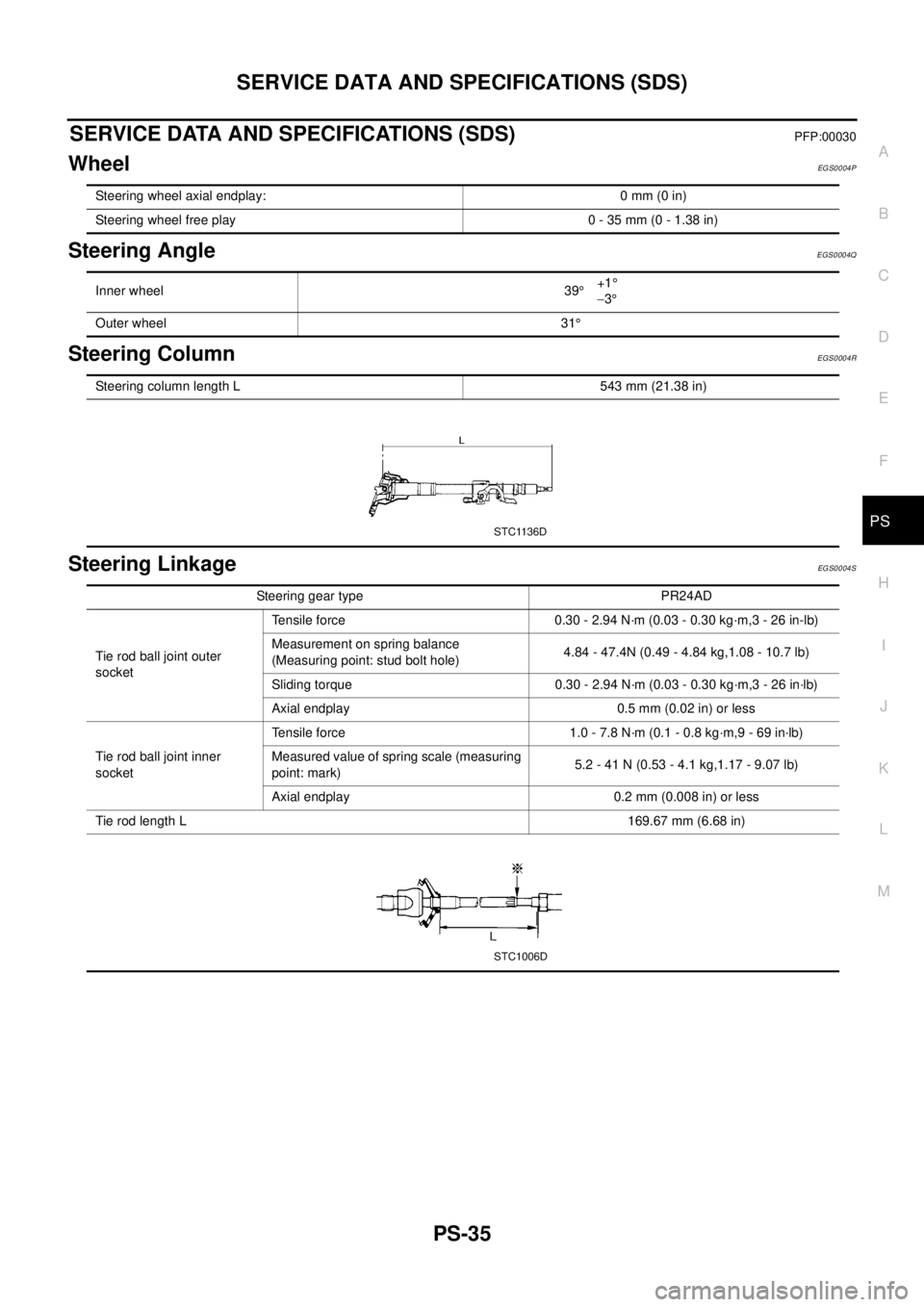
SERVICE DATA AND SPECIFICATIONS (SDS)PFP:00030
WheelEGS0004P
Steering AngleEGS0004Q
Steering ColumnEGS0004R
Steering LinkageEGS0004S
Steering wheel axial endplay: 0 mm (0 in)
Steering wheel free play 0 - 35 mm (0 - 1.38 in)
Inner wheel 39°+1°
-3°
Outer wheel 31°
Steering column length L 543 mm (21.38 in)
STC1136D
Steering gear type PR24AD
Tie rod ball joint outer
socketTensile force 0.30 - 2.94 N·m (0.03 - 0.30 kg·m,3 - 26 in-lb)
Measurement on spring balance
(Measuring point: stud bolt hole)4.84 - 47.4N (0.49 - 4.84 kg,1.08 - 10.7 lb)
Sliding torque 0.30 - 2.94 N·m (0.03 - 0.30 kg·m,3 - 26 in·lb)
Axial endplay 0.5 mm (0.02 in) or less
Tie rod ball joint inner
socketTensile force 1.0 - 7.8 N·m (0.1 - 0.8 kg·m,9 - 69 in·lb)
Measured value of spring scale (measuring
point: mark)5.2 - 41 N (0.53 - 4.1 kg,1.17 - 9.07 lb)
Axial endplay 0.2 mm (0.008 in) or less
Tie rod length L169.67 mm (6.68 in)
STC1006D
Page 2796 of 3066
PS-36
SERVICE DATA AND SPECIFICATIONS (SDS)
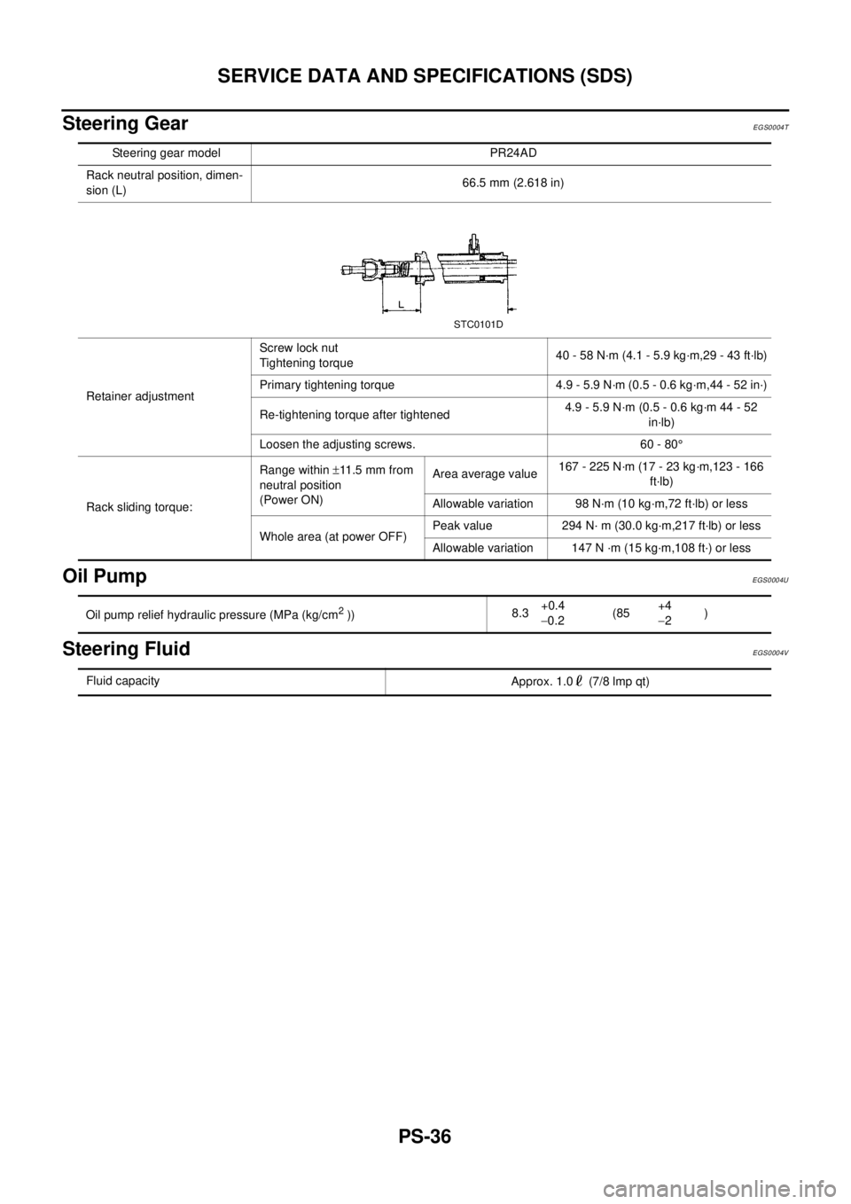
Steering Gear
EGS0004T
Oil PumpEGS0004U
Steering FluidEGS0004V
Steering gear model PR24AD
Rack neutral position, dimen-
sion (L)66.5 mm (2.618 in)
Retainer adjustmentScrew lock nut
Tightening torque40 - 58 N·m (4.1 - 5.9 kg·m,29 - 43 ft·lb)
Primary tightening torque 4.9 - 5.9 N·m (0.5 - 0.6 kg·m,44 - 52 in·)
Re-tightening torque after tightened4.9 - 5.9 N·m (0.5 - 0.6 kg·m 44 - 52
in·lb)
Loosen the adjusting screws. 60 - 80°
Rack sliding torque:Range within±11 .5 m m f r o m
neutral position
(Power ON)Area average value167 - 225 N·m (17 - 23 kg·m,123 - 166
ft·lb)
Allowable variation 98 N·m (10 kg·m,72 ft·lb) or less
Whole area (at power OFF)Peak value 294 N· m (30.0 kg·m,217 ft·lb) or less
Allowable variation 147 N ·m (15 kg·m,108 ft·) or less
STC0101D
Oil pump relief hydraulic pressure (MPa (kg/cm2))8.3+0.4
-0.2(85+4
-2)
Fluid capacity
Approx. 1.0 (7/8 lmp qt)
Page 2797 of 3066

RAX-1
REAR AXLE
D DRIVELINE/AXLE
CONTENTS
C
E
F
G
H
I
J
K
L
M
SECTION
A
B
RAX
REAR AXLE
PRECAUTIONS .......................................................... 2
Caution ..................................................................... 2
Precautions for Brake System .................................. 2
PREPARATION ........................................................... 3
Special Service Tools ............................................... 3
Commercial Service Tools ........................................ 4
NOISE, VIBRATION, AND HARSHNESS (NVH)
TROUBLESHOOTING ................................................ 5
NVH Troubleshooting Chart ..................................... 5
WHEEL HUB (4WD) ................................................... 6
On-Vehicle Inspection .............................................. 6
REAR WHEEL BEARING ..................................... 6
Removal and Installation .......................................... 6
REMOVAL ............................................................. 6INSTALLATION ..................................................... 7
Disassembly and Assembly ...................................... 7
DISASSEMBLY ..................................................... 7
INSPECTION AFTER DISASSEMBLY .................. 8
ASSEMBLY ........................................................... 8
REAR DRIVE SHAFT ................................................. 9
Removal and Installation .......................................... 9
REMOVAL ............................................................. 9
INSPECTION AFTER REMOVAL ......................... 9
INSTALLATION ..................................................... 9
Disassembly and Assembly .................................... 10
DISASSEMBLY ................................................... 10
INSPECTION AFTER DISASSEMBLY ................ 11
ASSEMBLY ......................................................... 12
SERVICE DATA AND SPECIFICATIONS (SDS) ...... 15
Wheel Bearing ........................................................ 15
Drive Shaft .............................................................. 15
Page 2798 of 3066
RAX-2
PRECAUTIONS
PRECAUTIONS
PFP:00001
CautionEDS00060
Observe the following precautions when disassembling and servicing drive shaft.
lPerform work in a location which is as dust-free and dirt-free as possible.
lBefore disassembling and servicing, clean the outside of parts.
lThe disassembly and service location must be clean. Care must be taken to prevent parts from becoming
dirty and to prevent the entry of foreign objects.
lDisassembled parts must be carefully reassembled in the correct order. If work is interrupted, a clean
cover must be placed over parts.
lPaper shop cloths must be used. Fabric shop cloths must not be used because of the danger of lint adher-
ing to parts.
lDisassembled parts (except for rubber parts) should be cleaned with kerosene which shall be removed by
blowing with air or wiping with paper shop cloths.
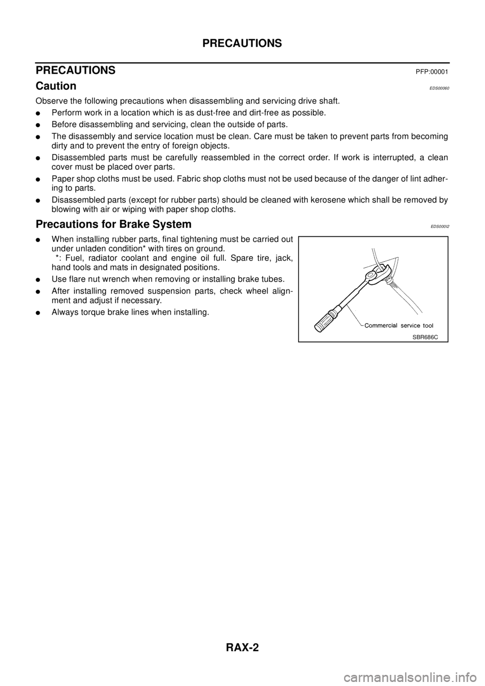
Precautions for Brake SystemEDS0 00 I2
lWhen installing rubber parts, final tightening must be carried out
under unladen condition* with tires on ground.
*: Fuel, radiator coolant and engine oil full. Spare tire, jack,
hand tools and mats in designated positions.
lUse flare nut wrench when removing or installing brake tubes.
lAfter installing removed suspension parts, check wheel align-
ment and adjust if necessary.
lAlways torque brake lines when installing.
SBR686C
Page 2799 of 3066
PREPARATION
RAX-3
C
E
F
G
H
I
J
K
L
MA
B
RAX
PREPARATIONPFP:00002
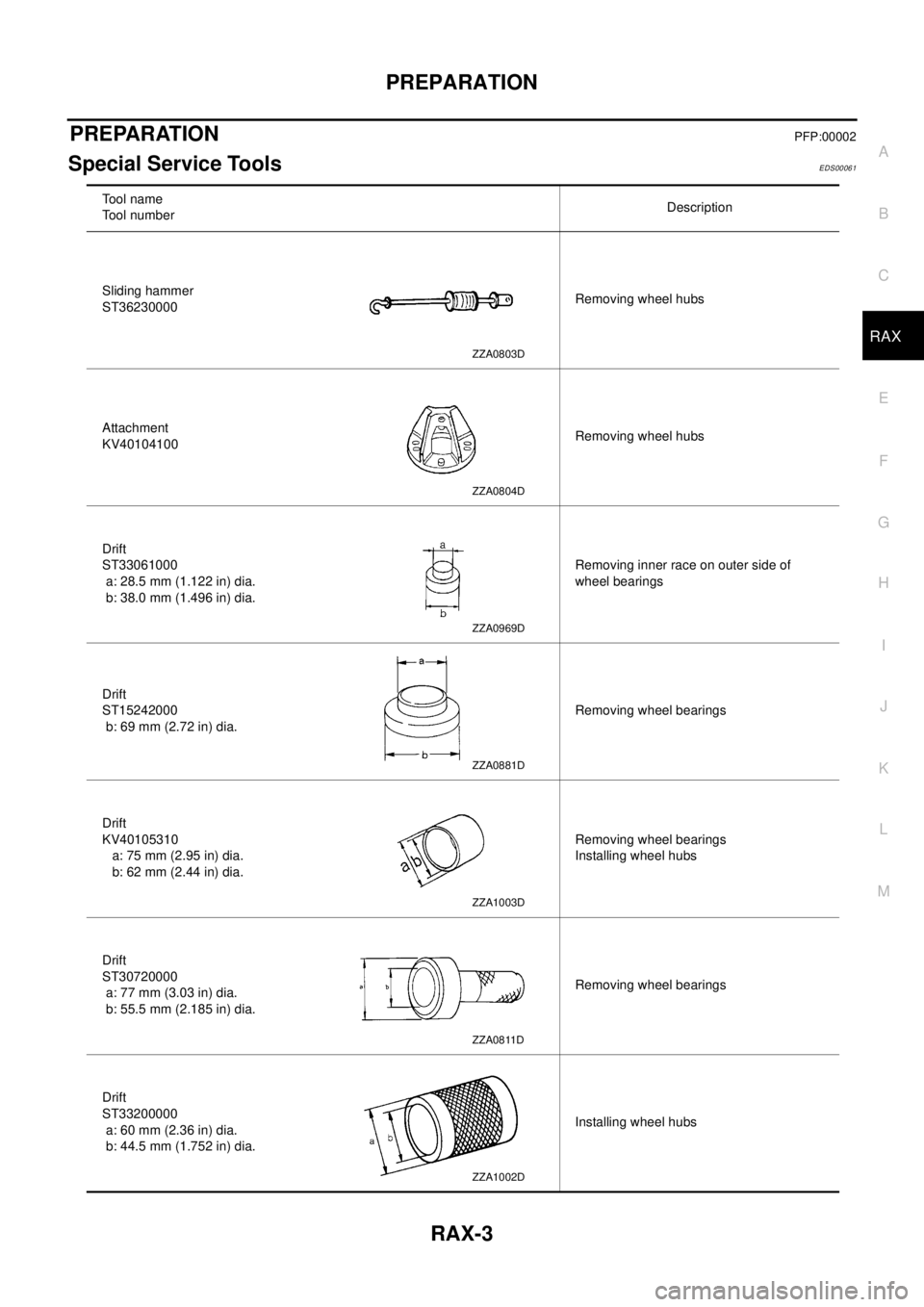
Special Service ToolsEDS00061
To o l n a m e
Tool numberDescription
Sliding hammer
ST36230000Removing wheel hubs
Attachment
KV40104100Removing wheel hubs
Drift
ST33061000
a: 28.5 mm (1.122 in) dia.
b: 38.0 mm (1.496 in) dia.Removing inner race on outer side of
wheel bearings
Drift
ST15242000
b: 69 mm (2.72 in) dia.Removing wheel bearings
Drift
KV40105310
a: 75 mm (2.95 in) dia.
b: 62 mm (2.44 in) dia.Removing wheel bearings
Installing wheel hubs
Drift
ST30720000
a: 77 mm (3.03 in) dia.
b: 55.5 mm (2.185 in) dia.Removing wheel bearings
Drift
ST33200000
a: 60 mm (2.36 in) dia.
b: 44.5 mm (1.752 in) dia.Installing wheel hubs
ZZA0803D
ZZA0804D
ZZA0969D
ZZA0881D
ZZA1003D
ZZA0811D
ZZA1002D
Page 2800 of 3066
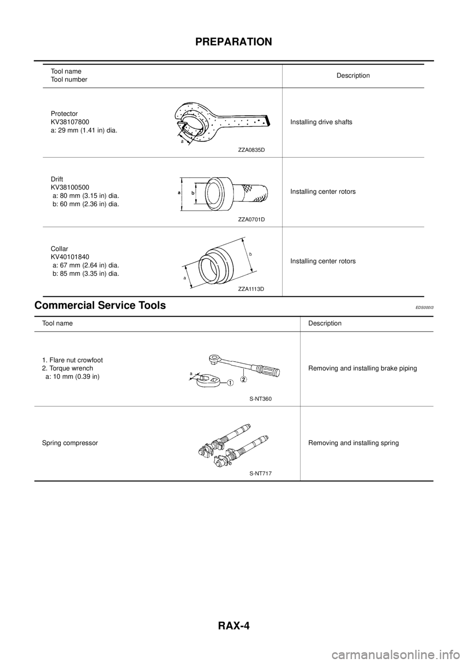
RAX-4
PREPARATION
Commercial Service Tools
EDS0 00 I3
Protector
KV38107800
a: 29 mm (1.41 in) dia.Installing drive shafts
Drift
KV38100500
a: 80 mm (3.15 in) dia.
b: 60 mm (2.36 in) dia.Installing center rotors
Collar
KV40101840
a: 67 mm (2.64 in) dia.
b: 85 mm (3.35 in) dia.Installing center rotors Tool name
Tool numberDescription
ZZA0835D
ZZA0701D
ZZA1113D
Tool nameDescription
1. Flare nut crowfoot
2. Torque wrench
a: 10 mm (0.39 in)Removing and installing brake piping
Spring compressor Removing and installing spring
S-NT360
S-NT717