TOYOTA CAMRY V20 1986 Service Information
CAMRY V20 1986
TOYOTA
TOYOTA
https://www.carmanualsonline.info/img/14/57449/w960_57449-0.png
TOYOTA CAMRY V20 1986 Service Information
Trending: warning, brakes, flat tire, clutch, tire type, trailer, fuel filter
Page 391 of 2389
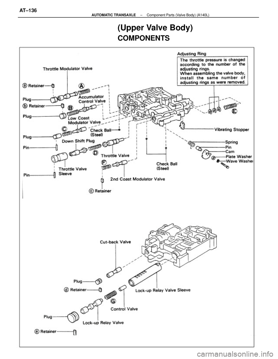
(Upper Valve Body)
COMPONENTS
± AUTOMATIC TRANSAXLEComponent Parts (Valve Body) (A140L)AT±136
Page 392 of 2389
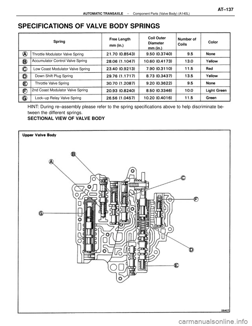
HINT: During re±assembly please refer to the spring specifications above to help discriminate be-
tween the different springs.
SECTIONAL VIEW OF VALVE BODY
SPECIFICATIONS OF VALVE BODY SPRINGS
Low Coast Modulator Valve Spring
2nd Coast Modulator Valve SpringAccumulator Control Valve SpringThrottle Modulator Valve Spring
Lock±up Relay Valve SpringCoil Outer
Diameter
mm (in.)
Down Shift Plug Spring
Throttle Valve SpringFree Length
mm (in.)Number of
Coils Spring
Color
± AUTOMATIC TRANSAXLEComponent Parts (Valve Body) (A140L)AT±137
Page 393 of 2389
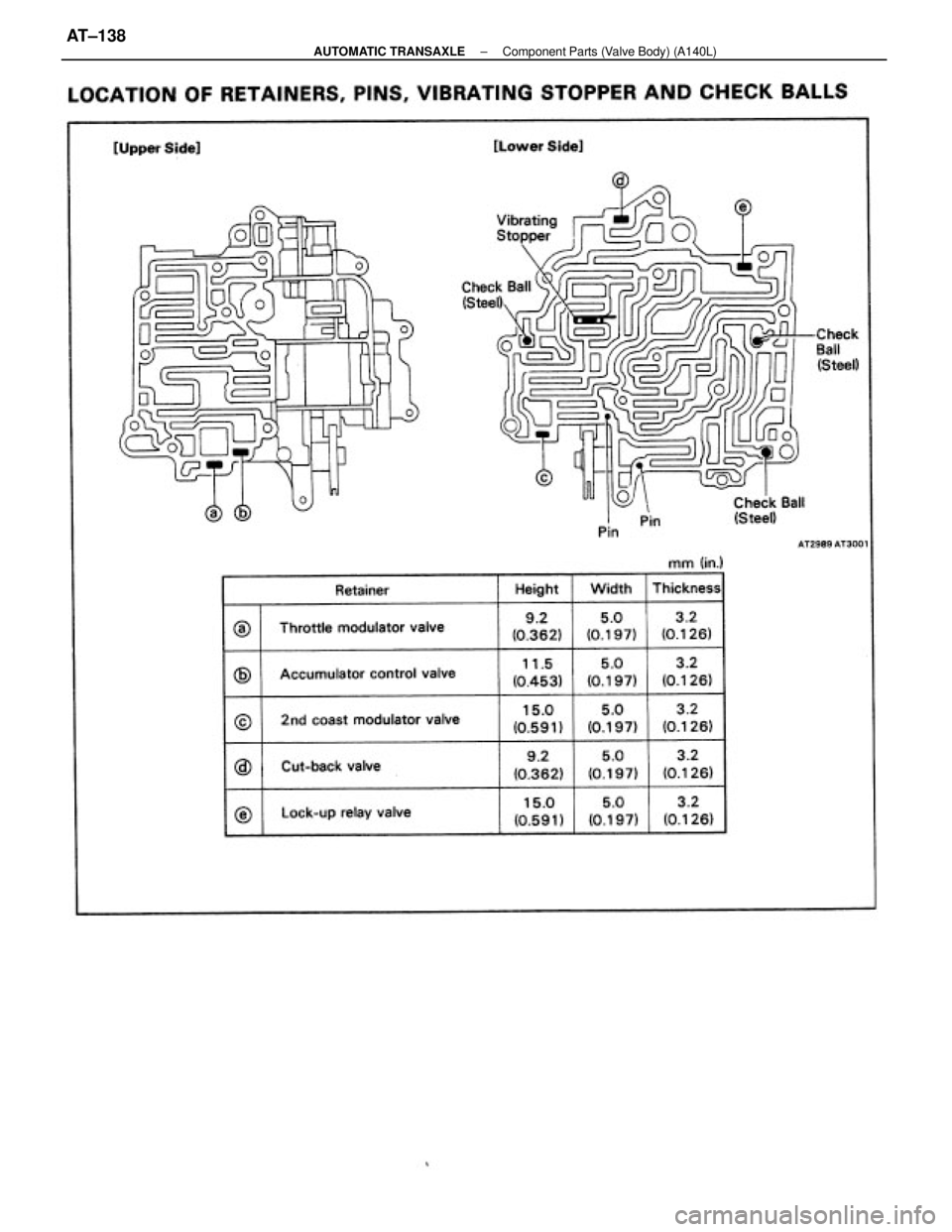
± AUTOMATIC TRANSAXLEComponent Parts (Valve Body) (A140L)AT±138
Page 394 of 2389
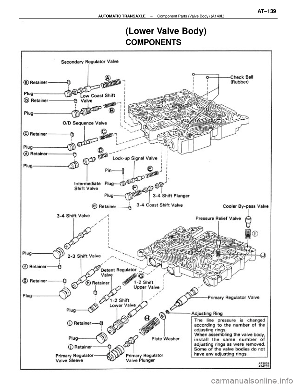
(Lower Valve Body)
COMPONENTS
± AUTOMATIC TRANSAXLEComponent Parts (Valve Body) (A140L)AT±139
Page 395 of 2389
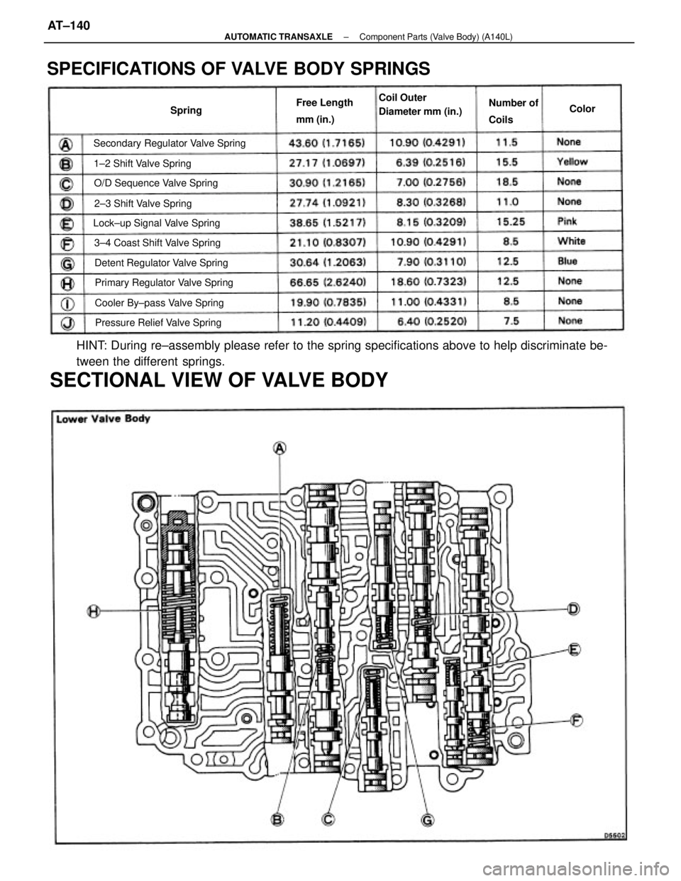
HINT: During re±assembly please refer to the spring specifications above to help discriminate be-
tween the different springs.
SECTIONAL VIEW OF VALVE BODY
SPECIFICATIONS OF VALVE BODY SPRINGS
Secondary Regulator Valve Spring
Primary Regulator Valve Spring Detent Regulator Valve Spring 3±4 Coast Shift Valve Spring Lock±up Signal Valve Spring
Cooler By±pass Valve Spring O/D Sequence Valve Spring
Pressure Relief Valve SpringCoil Outer
Diameter mm (in.)
2±3 Shift Valve Spring 1±2 Shift Valve SpringFree Length
mm (in.)Number of
Coils SpringColor
± AUTOMATIC TRANSAXLEComponent Parts (Valve Body) (A140L)AT±140
Page 396 of 2389
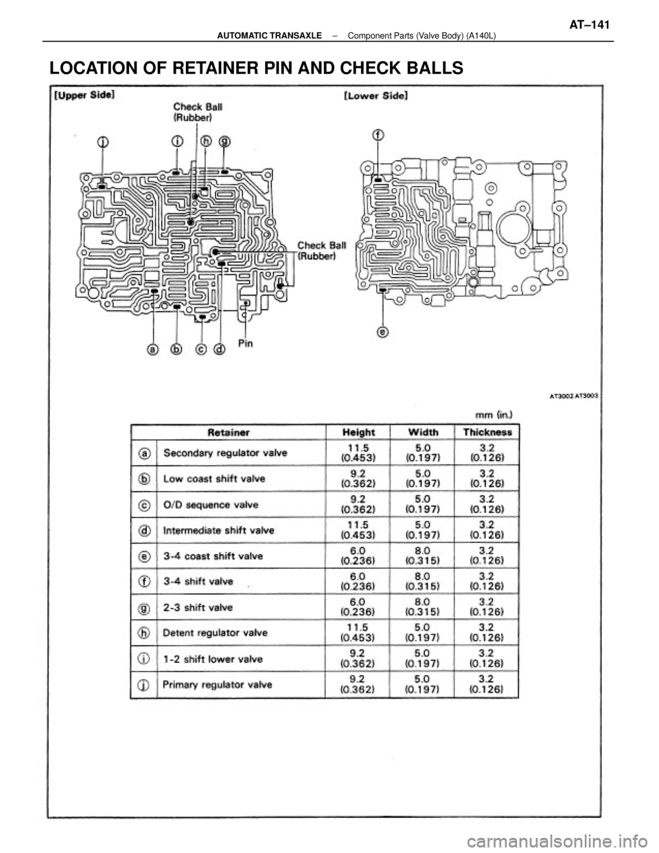
LOCATION OF RETAINER PIN AND CHECK BALLS
± AUTOMATIC TRANSAXLEComponent Parts (Valve Body) (A140L)AT±141
Page 397 of 2389
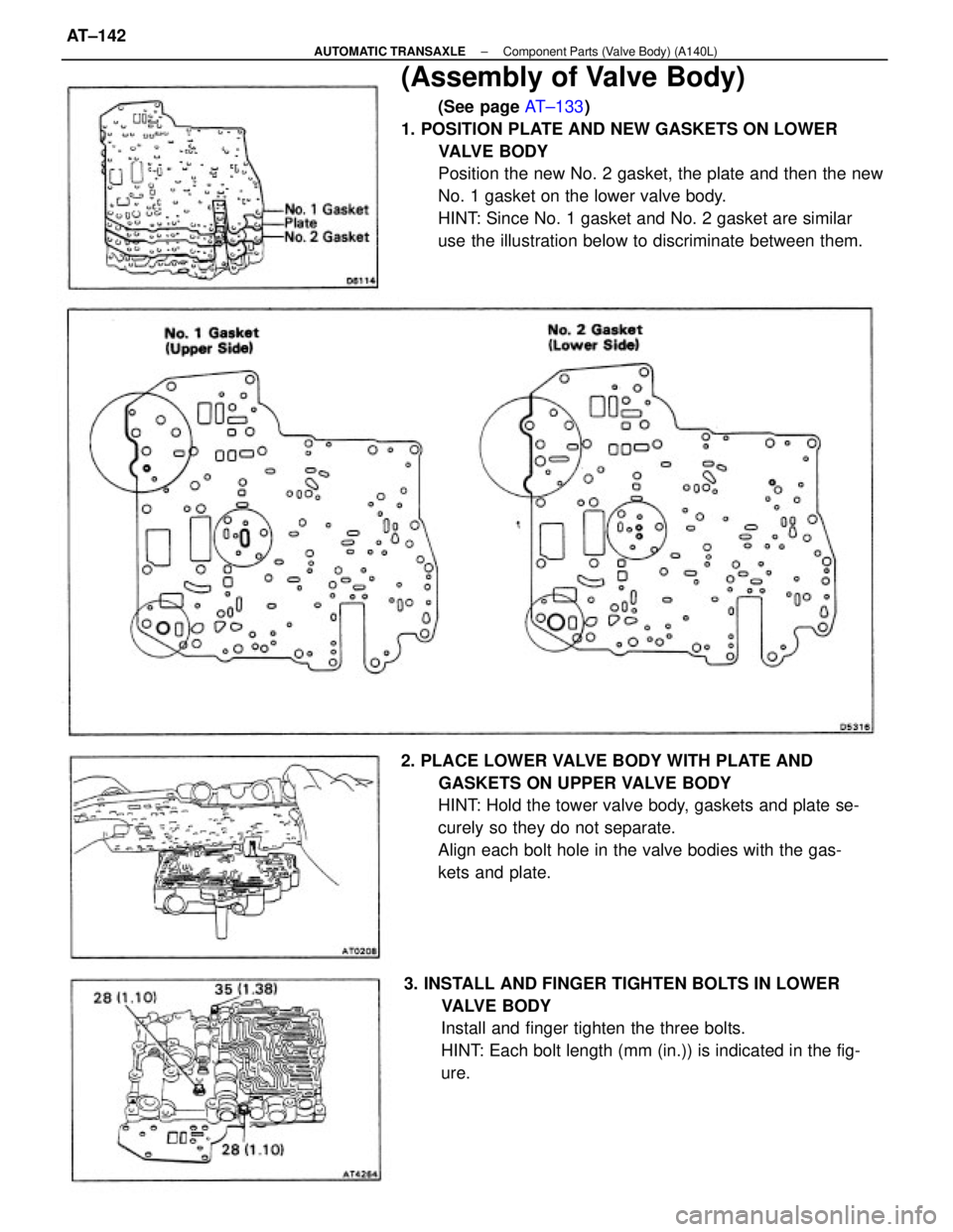
(Assembly of Valve Body)
(See page AT±133)
1. POSITION PLATE AND NEW GASKETS ON LOWER
VALVE BODY
Position the new No. 2 gasket, the plate and then the new
No. 1 gasket on the lower valve body.
HINT: Since No. 1 gasket and No. 2 gasket are similar
use the illustration below to discriminate between them.
2. PLACE LOWER VALVE BODY WITH PLATE AND
GASKETS ON UPPER VALVE BODY
HINT: Hold the tower valve body, gaskets and plate se-
curely so they do not separate.
Align each bolt hole in the valve bodies with the gas-
kets and plate.
3. INSTALL AND FINGER TIGHTEN BOLTS IN LOWER
VALVE BODY
Install and finger tighten the three bolts.
HINT: Each bolt length (mm (in.)) is indicated in the fig-
ure.
± AUTOMATIC TRANSAXLEComponent Parts (Valve Body) (A140L)AT±142
Page 398 of 2389
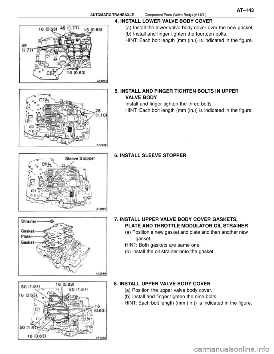
4. INSTALL LOWER VALVE BODY COVER
(a) Install the lower valve body cover over the new gasket.
(b) Install and finger tighten the fourteen bolts.
HINT: Each bolt length (mm (in.)) is indicated in the figure.
7. INSTALL UPPER VALVE BODY COVER GASKETS,
PLATE AND THROTTLE MODULATOR OIL STRAINER
(a) Position a new gasket and plate and then another new
gasket.
HINT: Both gaskets are same one.
(b) install the oil strainer onto the gasket.
8. INSTALL UPPER VALVE BODY COVER
(a) Position the upper valve body cover.
(b) Install and finger tighten the nine bolts.
HINT: Each bolt length (mm (in.)) is indicated in the figure. 5. INSTALL AND FINGER TIGHTEN BOLTS IN UPPER
VALVE BODY
Install and finger tighten the three bolts.
HINT: Each bolt length (mm (in.)) is indicated in the figure.
6. INSTALL SLEEVE STOPPER
± AUTOMATIC TRANSAXLEComponent Parts (Valve Body) (A140L)AT±143
Page 399 of 2389
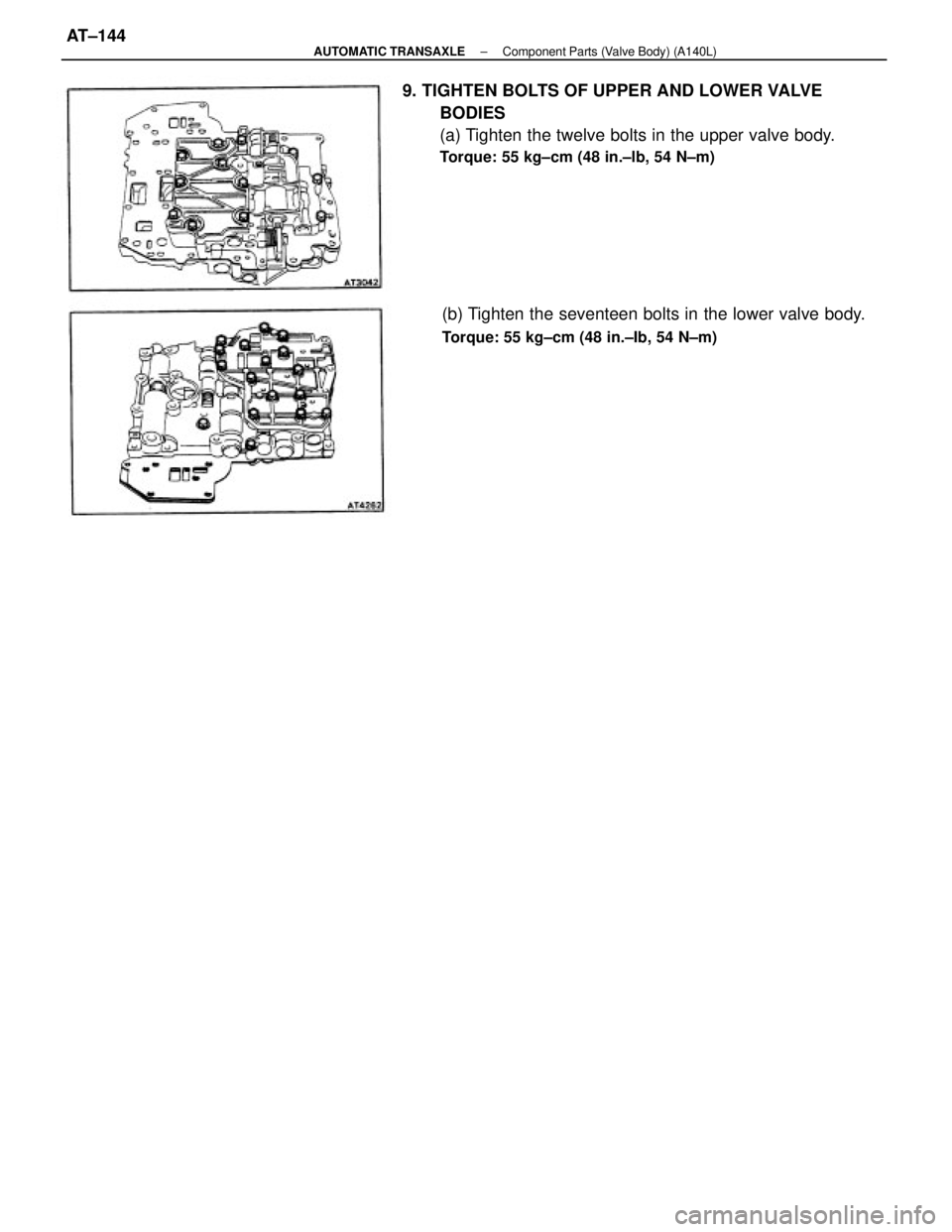
9. TIGHTEN BOLTS OF UPPER AND LOWER VALVE
BODIES
(a) Tighten the twelve bolts in the upper valve body.
Torque: 55 kg±cm (48 in.±lb, 54 N±m)
(b) Tighten the seventeen bolts in the lower valve body.
Torque: 55 kg±cm (48 in.±Ib, 54 N±m)
± AUTOMATIC TRANSAXLEComponent Parts (Valve Body) (A140L)AT±144
Page 400 of 2389
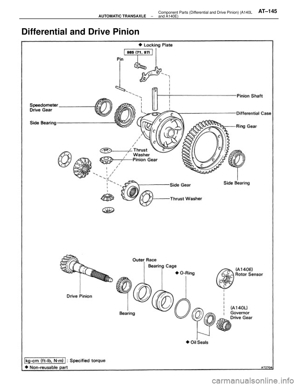
Differential and Drive Pinion
± AUTOMATIC TRANSAXLEComponent Parts (Differential and Drive Pinion) (A140L
and A140E)AT±145
Trending: change time, fuel pressure, buttons, brake pads replacement, low beam, maintenance, ignition
