TOYOTA RAV4 1996 Service Repair Manual
Manufacturer: TOYOTA, Model Year: 1996, Model line: RAV4, Model: TOYOTA RAV4 1996Pages: 1632, PDF Size: 41.64 MB
Page 1251 of 1632

1999 Toyota RAV4
1999 ACCESSORIES & EQUIPMENT Steering Column Switches - Trucks
Microsoft
Sunday, November 22, 2009 10:56:55 AMPage 23 © 2005 Mitchell Repair Information Company, LLC.
Page 1252 of 1632

Fig. 16: Horn System Wiring Diagram (2000 Tundra)
1999 Toyota RAV4
1999 ACCESSORIES & EQUIPMENT Steering Column Switches - Trucks
Microsoft
Sunday, November 22, 2009 10:56:55 AMPage 24 © 2005 Mitchell Repair Information Company, LLC.
Page 1253 of 1632

1999 Toyota RAV4
1999 ACCESSORIES & EQUIPMENT Steering Column Switches - Trucks
Microsoft
Sunday, November 22, 2009 10:56:55 AMPage 25 © 2005 Mitchell Repair Information Company, LLC.
Page 1254 of 1632

Fig. 17: Horn System Wiring Diagram (4Runner)
1999 Toyota RAV4
1999 ACCESSORIES & EQUIPMENT Steering Column Switches - Trucks
Microsoft
Sunday, November 22, 2009 10:56:55 AMPage 26 © 2005 Mitchell Repair Information Company, LLC.
Page 1255 of 1632
1999-2000 STEERING
Steering Columns - Tilt Wheel - Trucks & Vans
DESCRIPTION & OPERATION
Tilt steering columns incorporate a main shaft, attached by a "U" joint to an intermediate steering shaft. Shafts
are held in place by upper and lower column tubes. Column tubes are pinned together so upper column can
move up or down. Upper column is locked in place by pawl attached to lever. Steering columns are collapsible.
SERVICE PRECAUTIONS
Observe the following precautions when servicing SRS:
Disable SRS before servicing any SRS or steering column component. Failure to do this could result in
accidental air bag deployment and possible personal injury. See DISABLING & ACTIVATING AIR
BAG SYSTEM .
Remove air bag sensor assembly/center air bag sensor and front air bag sensors if repairing the vehicle
requires impacting (shocking) the vehicle.
Replace dropped, cracked, dented or otherwise damaged components.
DO NOT expose front air bag sensors, air bag sensor assembly/center air bag sensor or steering wheel
pad (air bag module) directly to heat or flame.
Information labels are attached to air bag components. Follow all notices on labels.
After work on SRS is completed, check air bag warning light to ensure system is functioning properly.
See appropriate AIR BAG RESTRAINT SYSTEMS article in ACCESSORIES & EQUIPMENT.
Always wear safety glasses when servicing or handling an air bag.
When placing a live air bag on a bench or other surface, always face air bag and trim cover upward, away
from surface. This will reduce motion of module if it is accidentally deployed.
Carry a live air bag module with trim cover (air bag) pointed away from your body to minimize injury in
case of accidental deployment.
If SRS is not fully functional for any reason, vehicle should not be driven until system is repaired and
becomes operational. DO NOT remove bulbs, modules, sensors or other components or in any way
disable system from operating normally. If SRS is not functional, park vehicle until it is repaired and
functions properly.
DISABLING & ACTIVATING AIR BAG SYSTEM
WARNING:To avoid injury from accidental air bag deployment, read and carefully
follow all SERVICE PRECAUTIONS
. Deactivate air bag system before
performing any repairs. See DISABLING & ACTIVATING AIR BAG
SYSTEM .
WARNING:Back-up power supply maintains SRS voltage for about 90 seconds after
1999 Toyota RAV4
1999-2000 STEERING Steering Columns - Tilt Wheel - Trucks & Vans
1999 Toyota RAV4
1999-2000 STEERING Steering Columns - Tilt Wheel - Trucks & Vans
Microsoft
Sunday, November 22, 2009 10:34:02 AMPage 1 © 2005 Mitchell Repair Information Company, LLC.
Microsoft
Sunday, November 22, 2009 10:34:07 AMPage 1 © 2005 Mitchell Repair Information Company, LLC.
Page 1256 of 1632
DISABLING SYSTEM
Turn ignition switch to LOCK position. Disconnect and shield negative battery cable. Wait at least 90 seconds
before working on system. Remove steering wheel pad (air bag module). See STEERING WHEEL & AIR
BAG under REMOVAL & INSTALLATION.
ACTIVATING SYSTEM
Install steering wheel pad. Reconnect negative battery cable. Perform system operation check. See appropriate
AIR BAG RESTRAINT SYSTEMS article in ACCESSORIES & EQUIPMENT.
ADJUSTMENTS
SPIRAL CABLE
Spiral cable must be correctly adjusted to ensure proper air bag operation. Ensure front wheels are in straight-
ahead position. Turn spiral cable counterclockwise by hand until it becomes difficult to turn. Turn spiral cable
clockwise 2 1/2 turns for Land Cruiser, Tacoma, Tundra and 4Runner. Turn spiral cable clockwise 3 turns for
4Runner and Sienna. Ensure marks ali
gn and are visible through inspection hole. See Fig. 1 . battery is disconnected. After disabling SRS, wait at least 90 seconds
before servicing SRS to prevent accidental air bag deployment and
possible personal injury.
1999 Toyota RAV4
1999-2000 STEERING Steering Columns - Tilt Wheel - Trucks & Vans
Microsoft
Sunday, November 22, 2009 10:34:02 AMPage 2 © 2005 Mitchell Repair Information Company, LLC.
Page 1257 of 1632
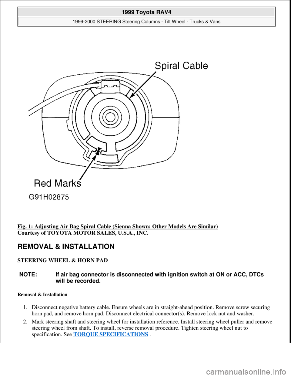
Fig. 1: Adjusting Air Bag Spiral Cable (Sienna Shown; Other Models Are Similar)
Courtesy of TOYOTA MOTOR SALES, U.S.A., INC.
REMOVAL & INSTALLATION
STEERING WHEEL & HORN PAD
Removal & Installation
1. Disconnect negative battery cable. Ensure wheels are in straight-ahead position. Remove screw securing
horn pad, and remove horn pad. Disconnect electrical connector(s). Remove lock nut and washer.
2. Mark steering shaft and steering wheel for installation reference. Install steering wheel puller and remove
steering wheel from shaft. To install, reverse removal procedure. Tighten steering wheel nut to
specification. See TORQUE SPECIFICATIONS
.
NOTE: If air bag connector is disconnected with ignition switch at ON or ACC, DTCs
will be recorded.
1999 Toyota RAV4
1999-2000 STEERING Steering Columns - Tilt Wheel - Trucks & Vans
Microsoft
Sunday, November 22, 2009 10:34:02 AMPage 3 © 2005 Mitchell Repair Information Company, LLC.
Page 1258 of 1632
STEERING WHEEL & AIR BAG
Removal & Installation
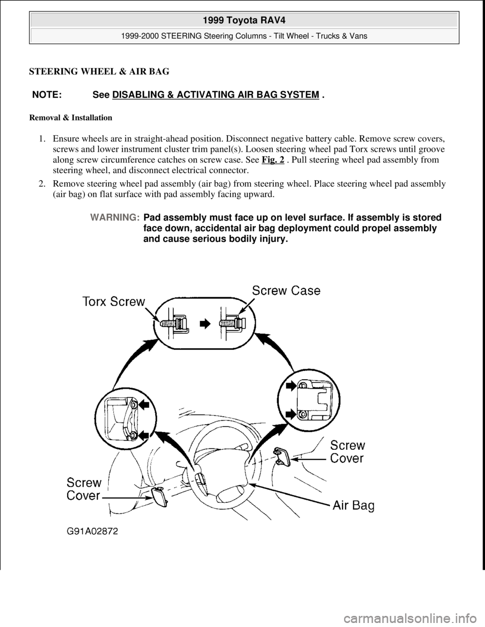
1. Ensure wheels are in straight-ahead position. Disconnect negative battery cable. Remove screw covers,
screws and lower instrument cluster trim panel(s). Loosen steering wheel pad Torx screws until groove
along screw circumference catches on screw case. See Fig. 2
. Pull steering wheel pad assembly from
steering wheel, and disconnect electrical connector.
2. Remove steering wheel pad assembly (air bag) from steering wheel. Place steering wheel pad assembly
(air bag) on flat surface with pad assembly facing upward. NOTE: See DISABLING & ACTIVATING AIR BAG SYSTEM
.
WARNING:Pad assembly must face up on level surface. If assembly is stored
face down, accidental air bag deployment could propel assembly
and cause serious bodily injury.
1999 Toyota RAV4
1999-2000 STEERING Steering Columns - Tilt Wheel - Trucks & Vans
Microsoft
Sunday, November 22, 2009 10:34:02 AMPage 4 © 2005 Mitchell Repair Information Company, LLC.
Page 1259 of 1632
Fig. 2: Removing Steering Wheel Pad (Typical)
Courtesy of TOYOTA MOTOR SALES, U.S.A., INC.
3. Remove lock nut and washer. Mark steering shaft and steering wheel for installation reference. Install
steering wheel puller, and remove steering wheel from shaft.
4. Prior to installation, ensure spiral cable (located on combination switch) is properly aligned. See SPIRAL
CABLE under ADJUSTMENTS. To complete installation, reverse removal procedure. Tighten steering
wheel nut to specification. See TORQUE SPECIFICATIONS
.
COMBINATION SWITCH
Removal & Installation
1. Disconnect negative battery cable. Remove steering wheel. See STEERING WHEEL & HORN PAD
or STEERING WHEEL & AIR BAG
. Remove instrument cluster lower finish panel. Remove upper
and lower steering column covers.
2. Disconnect combination switch electrical connectors and air bag connector. Remove combination switch
mounting screws, and remove combination switch. To install, reverse removal procedure. Tighten
steering wheel nut to specification. See TORQUE SPECIFICATIONS
.
IGNITION SWITCH & LOCK CYLINDER
Removal & Installation
1. Disconnect negative battery cable. Remove steering wheel, upper and lower steering column covers and
combination switch (if necessary).
2. Place ignition key at ACC position. Using screwdriver, push down stop pin of cylinder, and pull out lock
cylinder. Remove 2 screws and ignition switch.
3. To install, reverse removal procedure. Install combination switch, upper and lower steering column
covers and steering wheel. Tighten steering wheel nut to specification. See TORQUE
SPECIFICATIONS .
STEERING COLUMN
Removal & Installation (Land Cruiser)
1. Disconnect negative battery cable. Remove steering wheel. See STEERING WHEEL & HORN PAD
or STEERING WHEEL & AIR BAG
. Remove steering column upper and lower covers. See Fig. 4 .
Remove combination switch with spiral cable.
2. Remove scuff plate and cowl trim. Remove cluster finish panel. Remove lower No. 1 panel and left-side
lower panel. Remove No. 2 heater- to- register duct from under steering column.
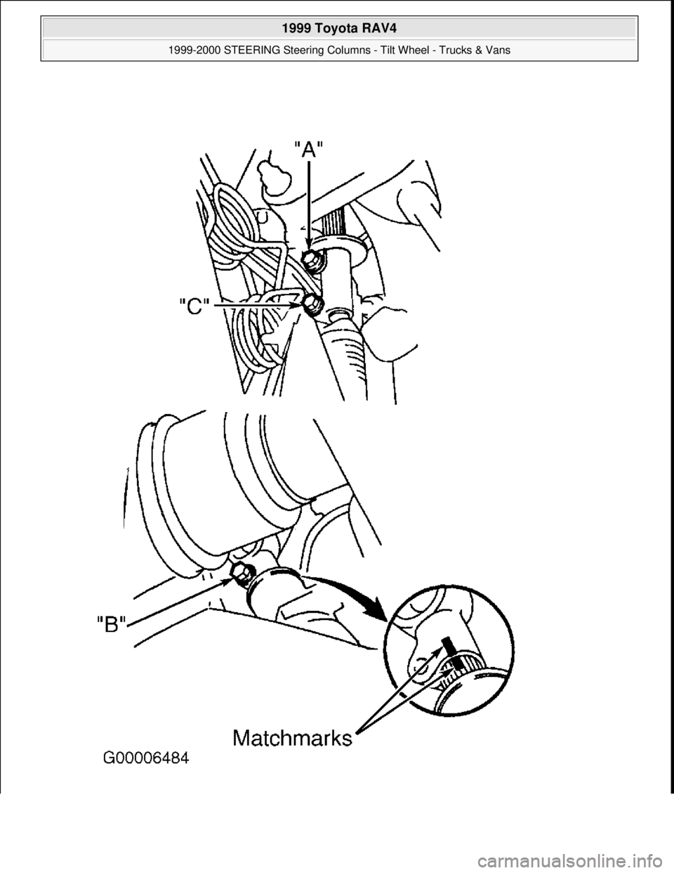
3. Mark intermediate shaft and control valve shaft for installation reference. Loosen bolt "A", and remove
bolts "B" and "C". See Fig. 3
. Disconnect No. 2 intermediate shaft assembly. Remove No. 2 intermediate
shaft assembl
y. Remove hole cover.
1999 Toyota RAV4
1999-2000 STEERING Steering Columns - Tilt Wheel - Trucks & Vans
Microsoft
Sunday, November 22, 2009 10:34:02 AMPage 5 © 2005 Mitchell Repair Information Company, LLC.
Page 1260 of 1632
1999 Toyota RAV4
1999-2000 STEERING Steering Columns - Tilt Wheel - Trucks & Vans
Microsoft
Sunday, November 22, 2009 10:34:02 AMPage 6 © 2005 Mitchell Repair Information Company, LLC.