TOYOTA RAV4 1996 Service Repair Manual
Manufacturer: TOYOTA, Model Year: 1996, Model line: RAV4, Model: TOYOTA RAV4 1996Pages: 1632, PDF Size: 41.64 MB
Page 1211 of 1632
and shield negative battery cable.
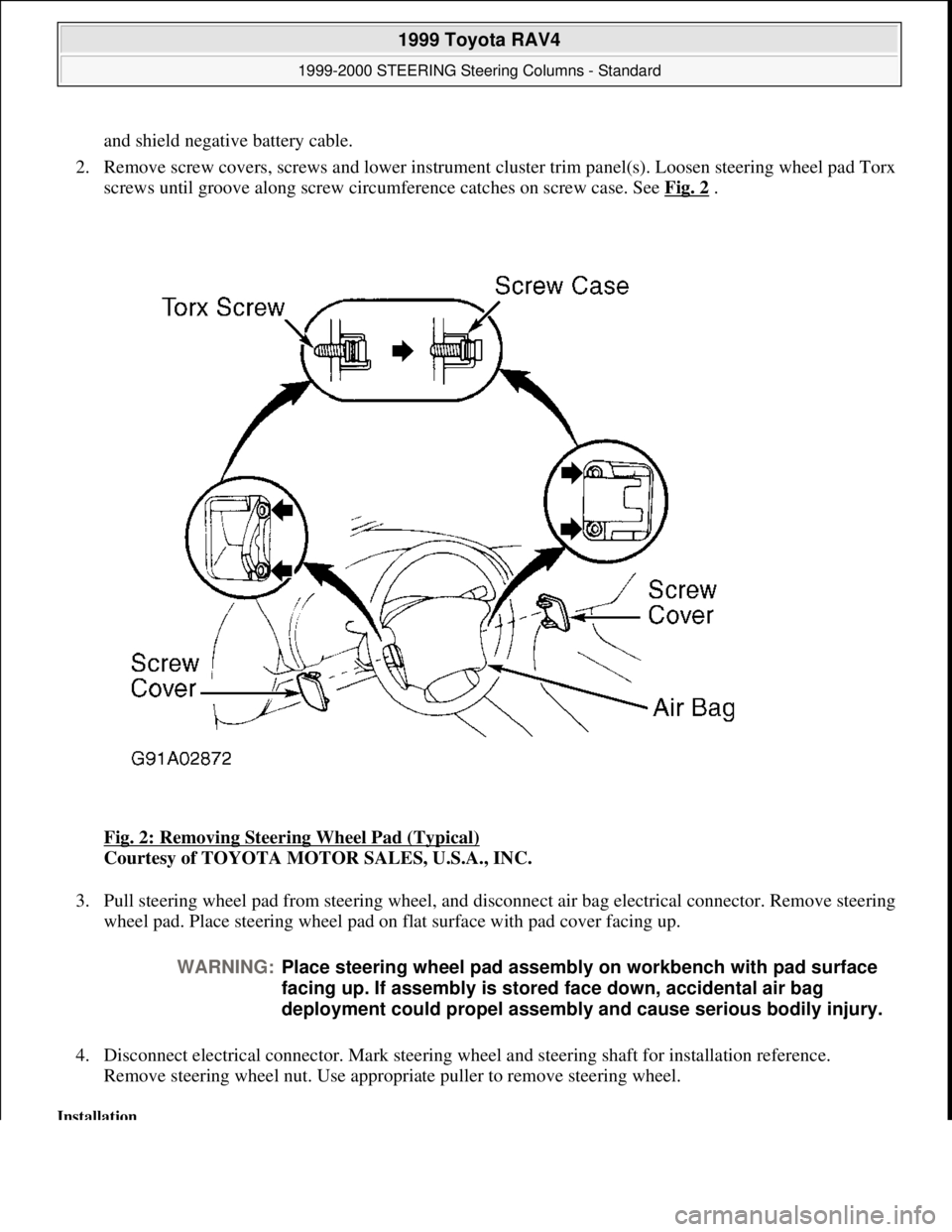
2. Remove screw covers, screws and lower instrument cluster trim panel(s). Loosen steering wheel pad Torx
screws until groove along screw circumference catches on screw case. See Fig. 2
.
Fig. 2: Removing Steering Wheel Pad (Typical)
Courtesy of TOYOTA MOTOR SALES, U.S.A., INC.
3. Pull steering wheel pad from steering wheel, and disconnect air bag electrical connector. Remove steering
wheel pad. Place steering wheel pad on flat surface with pad cover facing up.
4. Disconnect electrical connector. Mark steering wheel and steering shaft for installation reference.
Remove steering wheel nut. Use appropriate puller to remove steering wheel.
Installation
WARNING:Place steering wheel pad assembly on workbench with pad surface
facing up. If assembly is stored face down, accidental air bag
deployment could propel assembly and cause serious bodily injury.
1999 Toyota RAV4
1999-2000 STEERING Steering Columns - Standard
Microsoft
Sunday, November 22, 2009 10:34:51 AMPage 4 © 2005 Mitchell Repair Information Company, LLC.
Page 1212 of 1632
1. To install, reverse removal procedure. Before installing steering wheel, ensure spiral cable is properly
aligned. See ADJUSTMENTS
. Tighten steering wheel nut and Torx screws to specification. See
TORQUE SPECIFICATIONS
.
2. After steering wheel and steering wheel pad are installed, ensure proper operation of air bag system by
turning ignition switch to ACC or ON position. AIR BAG warning light should illuminate, then turn off
in about 6 seconds.
3. If AIR BAG warning light remains illuminated for more than 6 seconds, air bag system is malfunctioning
and needs repair. If AIR BAG warning light illuminates with ignition on, a short circuit is likely in AIR
BAG warning light circuit.
COMBINATION SWITCH
Removal & Installation
1. Disconnect and shield negative battery cable. Remove steering wheel. See STEERING WHEEL & AIR
BAG . Remove instrument cluster lower trim panel. Remove upper and lower steering column covers.
2. Disconnect combination switch electrical connector. Remove screws securing combination switch to
steering column and remove combination switch. To install, reverse removal procedure. Tighten steering
wheel nut to specification. See TORQUE SPECIFICATIONS
.
IGNITION SWITCH & LOCK CYLINDER
Removal
1. Disconnect and shield negative battery cable. Remove steering wheel. See STEERING WHEEL & AIR
BAG . Remove upper and lower steering column covers. Remove combination switch (if necessary).
2. Disconnect ignition switch harness connectors. If shear bolt studs are accessible, use a hacksaw to cut
slots into exposed studs. Using a screwdriver, remove studs.
3. If shear bolt studs are recessed or hard to reach with a hacksaw, center punch studs. Using a drill bit and
screw extractor, remove studs. Remove ignition switch, column upper bracket and lock cylinder.
4. To remove lock cylinder from column upper bracket, place ignition key to ACC position. Using a
screwdriver, push down on stop pin located on side of column upper bracket. Pull out lock cylinder.
Installation
1. To install, reverse removal procedure. Install NEW shear bolts. Tighten shear bolts finger tight. Ensure
proper operation of ignition switch and lock cylinder.
2. Tighten shear bolts until heads break off. Install combination switch, upper and lower steering column
covers and steering wheel. Tighten steering wheel nut to specification. See TORQUE
SPECIFICATIONS .
STEERING COLUMN
Removal & Installation (Celica)
1999 Toyota RAV4
1999-2000 STEERING Steering Columns - Standard
Microsoft
Sunday, November 22, 2009 10:34:51 AMPage 5 © 2005 Mitchell Repair Information Company, LLC.
Page 1213 of 1632
1. Disconnect and shield negative battery cable. Remove steering wheel pad. Remove steering wheel. See
STEERING WHEEL & AIR BAG
.
2. Remove upper and lower steering column covers. Disconnect connectors. Remove 4 screws and air bag
spiral and combination switch.
3. Remove instrument cluster lower finish panel. Remove fuse box opening cover. Remove 2 screws, and
disconnect hood release handle. Remove 5 retaining screws and instrument panel lower finish panel.
4. Remove remaining instrument cluster panel (4 bolts). Remove air duct from instrument panel outlet.
5. Loosen lower clamp bolt "A" from intermediate-to-steering gear "U" joint. Remove upper intermediate
shaft clamp bolt "B". See Fig. 3
. Place match marks on steering gear shaft and "U" joint. Fully remove
lower clamp bolt "A". Remove intermediate shaft.
6. To install, reverse removal procedure. Tighten all bolts to specifications. See TORQUE
SPECIFICATIONS . Ensure spiral cable is properly installed and adjusted. See SPIRAL CABLEunder
ADJUSTMENTS.
1999 Toyota RAV4
1999-2000 STEERING Steering Columns - Standard
Microsoft
Sunday, November 22, 2009 10:34:51 AMPage 6 © 2005 Mitchell Repair Information Company, LLC.
Page 1214 of 1632
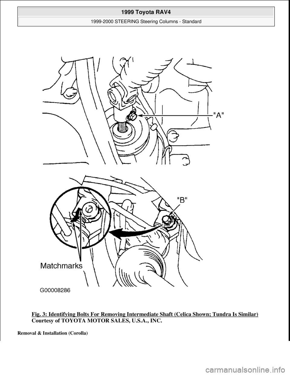
Fig. 3: Identifying Bolts For Removing Intermediate Shaft (Celica Shown; Tundra Is Similar)
Courtesy of TOYOTA MOTOR SALES, U.S.A., INC.
Removal & Installation (Corolla)
1999 Toyota RAV4
1999-2000 STEERING Steering Columns - Standard
Microsoft
Sunday, November 22, 2009 10:34:51 AMPage 7 © 2005 Mitchell Repair Information Company, LLC.
Page 1215 of 1632
1. Disconnect and shield negative battery cable. Remove steering wheel. See STEERING WHEEL & AIR
BAG .
2. Remove front door scuff plate and cowl side trim. Remove instrument cluster lower finish panel after
disconnecting hood release handle. Remove lower instrument panel insert.
3. Remove upper and lower steering column covers. Disconnect connectors. Remove 3 screws and air bag
spiral and combination switch.
4. Remove air duct from instrument panel outlet. Remove steering column floor hole cover (5 bolts).
5. Place match marks on steering gear shaft and "U" joint. Loosen upper "U" joint clamp bolt, and fully
remove lower "U" joint clamp bolt. Disconnect steering column assembly connectors. Remove 2 steering
column mounting bolts and nuts. Remove steering column from instrument panel.
6. Fully remove upper "U" joint clamp bolt. Remove "U" joint assembly.
7. To install, reverse removal procedure. Tighten all bolts to specifications. See TORQUE
SPECIFICATIONS . Ensure spiral cable is properly installed and adjusted. See SPIRAL CABLEunder
ADJUSTMENTS.
Removal & Installation (RAV4)
1. Disconnect and shield negative battery cable. Remove steering wheel. See STEERING WHEEL & AIR
BAG .
2. Remove lower instrument finish panel after disconnecting hood release handle. Remove lower instrument
panel insert.
3. Remove upper and lower steering column covers. Disconnect 2 electrical connectors and air bag
connector. Remove 3 screws and air bag spiral and combination switch. Remove air duct from instrument
panel outlet.
4. Place match marks on steering gear shaft and intermediate shaft across clamp. Loosen lower "U" joint
clamp bolt. Fully remove clamp bolt at steering gear connection.
5. Disconnect steering column assembly connectors. Loosen hole cover clamp bolt. Remove 2 steering
column mounting bolts and nuts. Remove steering column from instrument panel.
6. Remove floor hole cover. Fully remove upper "U" joint clamp bolt. Remove "U" joint assembly.
7. To install, reverse removal procedure. Tighten all bolts to specifications. See TORQUE
SPECIFICATIONS . Ensure spiral cable is properly installed and adjusted. See SPIRAL CABLEunder
ADJUSTMENTS.
Removal & Installation (Tacoma)
1. Disconnect and shield negative battery cable. Remove steering wheel. See STEERING WHEEL & AIR
BAG .
2. Remove upper and lower steering column covers. Disconnect hood release handle from instrument panel.
Remove 4 bolts and 1 screw. Remove instrument panel lower left finish panel. Remove air duct from
instrument panel outlet.
3. Disconnect 3 electrical connectors. Disconnect air bag connector. Remove 3 screws and combination
switch with spiral cable. Remove 2 bolts, and disconnect Junction Block No. 1.
4. On models with column shift, remove pin and clip, and disconnect cable assembly from steering column
1999 Toyota RAV4
1999-2000 STEERING Steering Columns - Standard
Microsoft
Sunday, November 22, 2009 10:34:51 AMPage 8 © 2005 Mitchell Repair Information Company, LLC.
Page 1216 of 1632
shift lever assembly.
5. If equipped with 2WD, place match marks across intermediate shaft and steering gear shaft. Loosen
clamp bolt just above floorboard. Remove lower "U" joint bolt at steering gear shaft connection.
Disconnect intermediate shaft. Fully remove bolt above floorboard, and remove intermediate shaft.
Remove steering column hole cover.
6. If equipped with 4WD, place match marks across intermediate shaft to steering gear housing. Loosen
upper clamp bolt (above yoke), and fully remove clamp bolt at connection to steering gear. Disconnect
intermediate shaft. Fully remove upper clamp bolt, and remove intermediate shaft. Remove steering
column floor hole cover.
7. On all models, disconnect column electrical connectors. Remove 2 steering column retaining bolts and
nuts. Remove steering column.
8. If equipped with 2WD, place match marks across column sliding yoke "U" joint connections. Remove
sliding yoke.
9. If equipped with 4WD, place match marks across column "U" joint connections above floor hole cover.
Remove upper clamp bolt. Remove "U" joint. Remove floor hole cover.
10. To install, reverse removal procedure. Tighten all bolts to specifications. See TORQUE
SPECIFICATIONS . Ensure spiral cable is properly installed and adjusted. See SPIRAL CABLEunder
ADJUSTMENTS.
Removal (Tundra)
1. Disconnect and shield negative battery cable. Remove steering wheel. See STEERING WHEEL & AIR
BAG .
2. Remove 3 screws and upper and lower steering column covers. Disconnect electrical connectors and air
bag connector. Remove 3 screws and air bag spiral and combination switch with spiral cable.
3. Remove instrument lower finish panel. Remove 2 screws, and disconnect hood release lever from panel.
Remove 4 bolts and instrument panel lower finish panel.
4. Remove No. 2 heater-to-register duct and brake pedal return spring.
5. Place match marks on No. 2 "U" joint and No. 2 intermediate shaft assembly. See Fig. 3
. Remove bolt
"A". Place match marks on No. 2 intermediate shaft assembly and control valve shaft. Remove bolt "B".
Remove No. 2 intermediate shaft assembly. Remove 3 bolts and column hole cover No. 2.
6. On models equipped with A/T, disconnect cable assembly from column shift lever assembly. Disconnect
connectors. Remove 4 steering column set nuts. Pull out steering column assembly with No. 2 "U" joint
assembly.
7. Place match marks on steering column assembly and No. 2 "U" joint assembly. Remove bolt and column
hole cover No. 2. Disconnect No. 2 "U" joint assembly.
Installation
1. Insert column hole cover No. 2. Align match marks on column assembly and No. 2 "U" joint assembly.
Install bolt to connect No. 2 "U" joint assembly.
2. Install column assembly with No. 2 "U" joint assembly. Install 4 steering column set nuts. Connect
connectors. On models equipped with A/T, connect transmission control cable assembly to shift lever
assembly.
1999 Toyota RAV4
1999-2000 STEERING Steering Columns - Standard
Microsoft
Sunday, November 22, 2009 10:34:51 AMPage 9 © 2005 Mitchell Repair Information Company, LLC.
Page 1217 of 1632
3. Align match marks on No. 2 "U" joint assembly and No. 2 intermediate shaft assembly. Align match
marks on control valve shaft and No. 2 intermediate shaft assembly. Install "A" and "B" bolts. See Fig. 3
.
4. Install brake pedal return spring and No. 2 heater to register duct. Install lower finish panel with 4 bolts.
Connect hood lock release lever with 2 screws. Install spiral cable. See SPIRAL CABLE
under
ADJUSTMENTS. Install combination switch with 3 screws. Connect air bag and connectors.
5. Install lower and upper column covers with 3 screws. Ensure tires are in straight-ahead position. Turn
cable counterclockwise until there is resistance. Rotate cable clockwise 2.5 turns to align mark.
6. To install steering wheel, align match marks on wheel and main shaft. Install wheel set nut. Connect
connector. Install steering wheel pad. Connect air bag connector. Install wheel pad when Torx screw is
set in screw case. Using a Torx socket wrench, tighten 2 screws to 78 INCH lbs. (8.8 N.m). Install 2
steering wheel lower No. 2 covers. Check steering wheel center point.
7. Tighten all bolts to specifications. See TORQUE SPECIFICATIONS
. Ensure spiral cable is properly
installed and adjusted. See SPIRAL CABLE
under ADJUSTMENTS.
Removal & Installation (4Runner)
1. Disconnect and shield negative battery cable. Remove steering wheel. See STEERING WHEEL & AIR
BAG .
2. Remove upper and lower steering column covers. Disconnect hood release handle from instrument panel.
Remove fuel lid release lever from instrument panel. Remove 4 bolts and instrument panel lower left
finish panel.
3. Remove starter switch bezel. Remove air duct from instrument panel outlet.
4. Disconnect 3 electrical connectors. Disconnect air bag connector. Remove 3 screws and combination
switch. Remove spiral cable. Remove brake pedal return spring.
5. Place match marks on intermediate shaft and "U" joint, and place match marks on steering gear shaft and
"U" joint. Remove upper and lower clamp bolts from "U" joint. Remove intermediate shaft.
6. Remove floor hole cover. Fully remove upper "U" joint clamp bolt, and remove "U" joint assembly.
7. To install, reverse removal procedure. Tighten all bolts to specifications. See TORQUE
SPECIFICATIONS . Ensure spiral cable is properly installed and adjusted. See SPIRAL CABLEunder
ADJUSTMENTS.
OVERHAUL
STEERING COLUMN
Disassembly (Celica)
1. Place intermediate shaft in vise. Place match marks across intermediate shaft and main shaft. Remove key
cylinder illumination assembly.
2. Center punch and drill into both upper column bracket bolts. Use screw extractor to remove bolts.
3. Remove snap ring from shaft assembly. Using brass bar and hammer, tap out shaft assembly bushing
from column tube. Remove remaining snap ring. See Fig. 5
.
Inspection
1999 Toyota RAV4
1999-2000 STEERING Steering Columns - Standard
Microsoft
Sunday, November 22, 2009 10:34:51 AMPage 10 © 2005 Mitchell Repair Information Company, LLC.
Page 1218 of 1632
Ensure lock mechanism, key cylinder, key interlock solenoid (A/T), and ignition switch operate properly. Check
column bearing for rotating smoothness. Replace column housing if bearing or housing shows any damage.
Check steering shaft for bends, damaged splines or damaged "U" joints. Repair or replace components as
necessary.
Reassembly
1. Install NEW snap ring to shaft assembly. Install shaft assembly into column tube. Install NEW snap ring
to retain shaft assembly in column.
2. Coat inside of new bushing with molybdenum disulfide lithium-based grease. Press NEW bushing into
column housing.
3. Install column upper bracket and clamp, using 2 NEW taper-head screws. Tighten until screw heads
break off.
4. Install key cylinder illumination assembly. Align all match marks on intermediate shaft and main shaft.
Install and tighten all bolts to specifications. See TORQUE SPECIFICATIONS
.
Disassembly (Corolla)
Place steering column assembly in vise. Remove key cylinder illumination assembly. Center punch and drill
into both steering column bracket bolts. Use screw extractor to remove bolts. See Fig. 6
.
Inspection
Ensure lock mechanism, key cylinder, key unlock warning switch, key interlock solenoid and ignition switch
operate properly. Check steering shaft for any signs of damage. Repair or replace components as necessary.
Reassembly
To reassemble, reverse disassembly procedure. Install and tighten all bolts to specifications. See TORQUE
SPECIFICATIONS .
Disassembly (RAV4)
1. Place steering column assembly in vise. Remove sliding yoke after making match marks across shaft and
"U" joint. Center punch and drill into both steering column bracket bolts. Use screw extractor to remove
bolts.
2. Remove column tube support bolt. Remove tube support with lower column tube attachment. Remove
tube attachment from tube support. See Fig. 7
.
3. Using pliers, remove energy absorbing clips. Remove energy absorbing plate, guide and breakaway
capsule. Turn nut clockwise to remove. See Fig. 4
.
4. Remove snap ring. Using brass bar and hammer, tap shaft assembly from column tube. Using
screwdriver, tap out bushin
g from lower end of tube.
1999 Toyota RAV4
1999-2000 STEERING Steering Columns - Standard
Microsoft
Sunday, November 22, 2009 10:34:51 AMPage 11 © 2005 Mitchell Repair Information Company, LLC.
Page 1219 of 1632
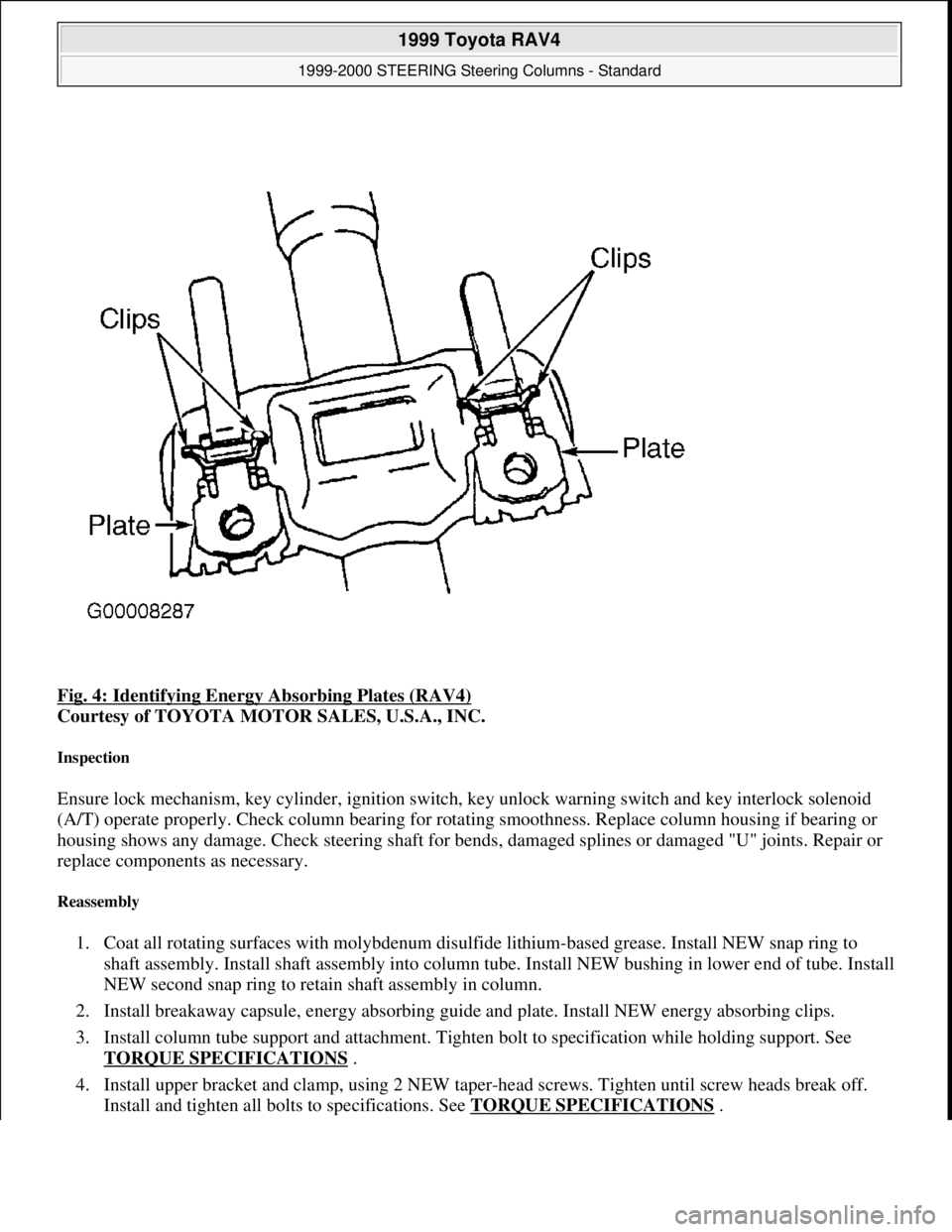
Fig. 4: Identifying Energy Absorbing Plates (RAV4)
Courtesy of TOYOTA MOTOR SALES, U.S.A., INC.
Inspection
Ensure lock mechanism, key cylinder, ignition switch, key unlock warning switch and key interlock solenoid
(A/T) operate properly. Check column bearing for rotating smoothness. Replace column housing if bearing or
housing shows any damage. Check steering shaft for bends, damaged splines or damaged "U" joints. Repair or
replace components as necessary.
Reassembly
1. Coat all rotating surfaces with molybdenum disulfide lithium-based grease. Install NEW snap ring to
shaft assembly. Install shaft assembly into column tube. Install NEW bushing in lower end of tube. Install
NEW second snap ring to retain shaft assembly in column.
2. Install breakaway capsule, energy absorbing guide and plate. Install NEW energy absorbing clips.
3. Install column tube support and attachment. Tighten bolt to specification while holding support. See
TORQUE SPECIFICATIONS
.
4. Install upper bracket and clamp, using 2 NEW taper-head screws. Tighten until screw heads break off.
Install and ti
ghten all bolts to specifications. See TORQUE SPECIFICATIONS .
1999 Toyota RAV4
1999-2000 STEERING Steering Columns - Standard
Microsoft
Sunday, November 22, 2009 10:34:51 AMPage 12 © 2005 Mitchell Repair Information Company, LLC.
Page 1220 of 1632
Disassembly (Tacoma)
1. Place steering column assembly in vise. Center punch and drill into both steering column bracket bolts.
Use screw extractor to remove bolts.
2. Remove snap ring from shaft assembly. Using soft-face hammer, tap shaft assembly from column tube.
Remove following snap ring.
3. Remove turn signal bracket and column shift lever assembly. See Fig. 8
.
Inspection
Ensure lock mechanism, key cylinder, ignition switch, key unlock warning switch and key interlock solenoid
(A/T) operate properly. Check column bearing for rotating smoothness. Replace column housing if bearing or
housing shows any damage. Check steering shaft for bends, damaged splines or any other damage. Repair or
replace components as necessary.
Reassembly
1. If replacing column tube bushing, coat inside of NEW bushing with molybdenum disulfide lithium-based
grease. Align projections on bushing with holes in column tube, and install bushing until projections are
engaged.
2. Coat all rotating surfaces with molybdenum disulfide lithium-based grease. Install column shift lever
assembly and turn signal bracket.
3. Install NEW snap ring to shaft assembly. Install shaft assembly into column tube. Install NEW second
snap ring to retain shaft assembly in column.
4. Install upper bracket and clamp, using 2 NEW taper-head screws. Tighten until screw heads break off.
Install and tighten all bolts to specifications. See TORQUE SPECIFICATIONS
.
Disassembly (Tundra)
1. Place steering column assembly in vise. Remove clip and key cylinder lamp assembly. Using punch,
mark center of 2 tapered-head bolts. Drill out 2 bolts. Remove 2 bolts, using screw extractor. Remove
column upper bracket and column upper clamp. On models equipped with A/T, remove shift lever, upper
No. 2 steering cover, park lock cable assembly and shift lever housing. See Fig. 9
.
2. Remove 4 Torx bolts and column upper tube with main shaft assembly from column tube assembly.
3. On models equipped with A/T, remove 4 Torx bolts and steering column housing support. On all models,
to remove column tube support, remove bolt and washer. Remove column tube support with lower
column tube attachment. Remove lower column tube attachment from column tube support.
4. Remove main shaft stopper and assembly. Ensure shaft assembly does not rotate. Using screwdriver,
remove retaining ring. Remove spring retainer and compression spring.
Inspection
Ensure lock mechanism, key cylinder, ignition switch and key unlock warning switch operate properly. Check
column bearing for rotating smoothness. Replace column housing if bearing or housing shows any damage.
Check steering shaft for bends, damaged splines or damaged "U" joints. Repair or replace components as
necessar
y.
1999 Toyota RAV4
1999-2000 STEERING Steering Columns - Standard
Microsoft
Sunday, November 22, 2009 10:34:51 AMPage 13 © 2005 Mitchell Repair Information Company, LLC.