TOYOTA RAV4 1996 Service Repair Manual
Manufacturer: TOYOTA, Model Year: 1996, Model line: RAV4, Model: TOYOTA RAV4 1996Pages: 1632, PDF Size: 41.64 MB
Page 1261 of 1632
Fig. 3: Locating No. 2 Intermediate Shaft Assembly Bolts
Courtesy of TOYOTA MOTOR SALES, U.S.A., INC.
4. Remove steering column assembly. Remove hose clamp. Remove No. 2 hole cover.
5. To install, install No. 2 hole cover. Install clamp. Install thrust stopper and sliding yoke to steering
column assembly. Install and temporarily tighten bolt "A". Install steering column assembly with 4 nuts.
Tighten to specification. See TORQUE SPECIFICATIONS
. Tighten clamp and connect connectors.
6. Install hole cover. Align match marks on No. 2 intermediate shaft and control valve shaft. Install bolts
"A", "B" and "C". Tighten bolts to specification. See TORQUE SPECIFICATIONS
To install
remaining components, reverse removal procedure. Tighten bolts and nuts to specification. See
TORQUE SPECIFICATIONS
.
1999 Toyota RAV4
1999-2000 STEERING Steering Columns - Tilt Wheel - Trucks & Vans
Microsoft
Sunday, November 22, 2009 10:34:02 AMPage 7 © 2005 Mitchell Repair Information Company, LLC.
Page 1262 of 1632
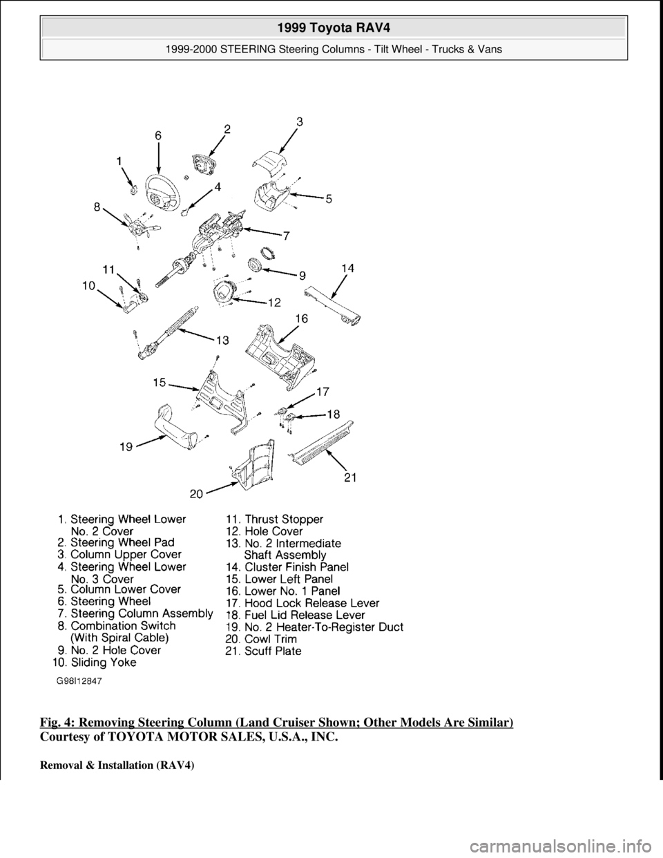
Fig. 4: Removing Steering Column (Land Cruiser Shown; Other Models Are Similar)
Courtesy of TOYOTA MOTOR SALES, U.S.A., INC.
Removal & Installation (RAV4)
1999 Toyota RAV4
1999-2000 STEERING Steering Columns - Tilt Wheel - Trucks & Vans
Microsoft
Sunday, November 22, 2009 10:34:02 AMPage 8 © 2005 Mitchell Repair Information Company, LLC.
Page 1263 of 1632
1. Disconnect negative battery cable. Remove steering wheel. See STEERING WHEEL & AIR BAG .
Remove upper and lower column covers. See Fig. 4
. Remove lower left-side instrument finish panel and
panel insert from under steering column. Remove combination switch with spiral cable. Remove No. 2
heater-to-register duct.
2. Mark shaft assembly and control valve for installation reference. Remove bolts, and disconnect No. 2
intermediate shaft assembly. Remove steering column assembly. Disconnect steering column harness
connectors.
3. Remove No. 2 intermediate shaft assembly. Remove column hole cover. To install, reverse removal
procedure. Tighten bolts and nuts to specification. See TORQUE SPECIFICATIONS
.
Removal & Installation (Sienna)
1. Disconnect negative battery cable. Remove steering wheel. See STEERING WHEEL & HORN PAD
or STEERING WHEEL & AIR BAG
. Remove front door inside scuff plate. Remove lower left-side
finish panel and left-side lower instrument panel. Remove upper and lower column covers. See Fig. 5
.
1999 Toyota RAV4
1999-2000 STEERING Steering Columns - Tilt Wheel - Trucks & Vans
Microsoft
Sunday, November 22, 2009 10:34:02 AMPage 9 © 2005 Mitchell Repair Information Company, LLC.
Page 1264 of 1632
1999 Toyota RAV4
1999-2000 STEERING Steering Columns - Tilt Wheel - Trucks & Vans
Microsoft
Sunday, November 22, 2009 10:34:02 AMPage 10 © 2005 Mitchell Repair Information Company, LLC.
Page 1265 of 1632
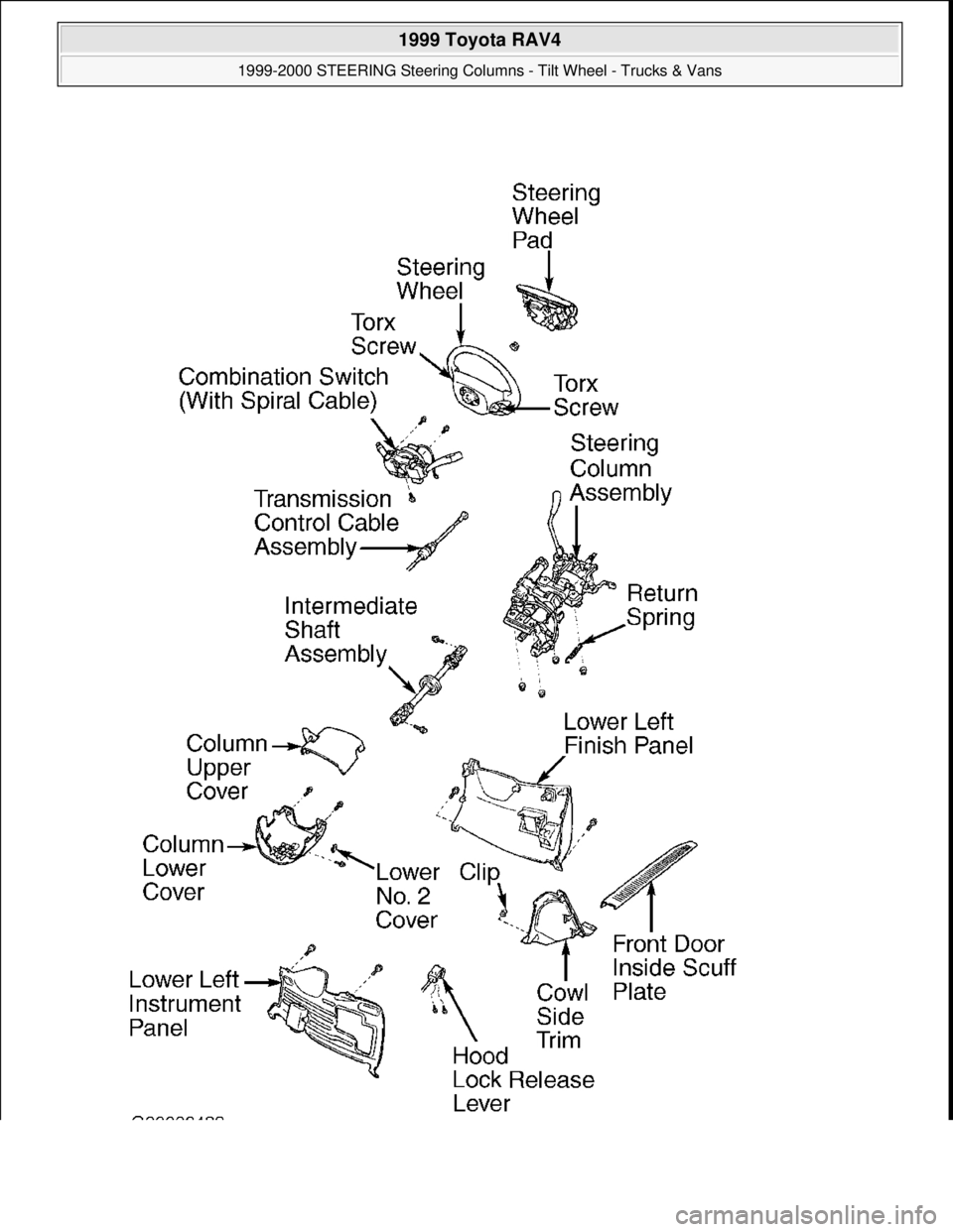
Fig. 5: Exploded View Of Steering Column (Sienna)
Courtesy of TOYOTA MOTOR SALES, U.S.A., INC.
2. Remove combination switch with spiral cable. Reference mark intermediate shaft and control valve shaft.
Disconnect intermediate shaft assembly. Disconnect transmission control cable assembly. Remove
intermediate shaft assembly. Remove steering column assembly.
3. To install, reverse removal procedure. Tighten bolts and nuts to specification. See TORQUE
SPECIFICATIONS .
Removal & Installation (Tacoma)
1. Disconnect negative battery cable. Remove steering wheel. See STEERING WHEEL & HORN PAD
or STEERING WHEEL & AIR BAG
. Remove upper and lower column covers. See Fig. 4 . Remove
left-side lower finish panel. Remove No. 2 heater-to- register duct from under steering column.
2. Remove combination switch with spiral cable. Disconnect junction block No. 1. Disconnect transmission
control cable assembly from column shift lever assembly.
3. On 2WD models, mark intermediate No. 2 shaft and control shaft for installation reference. Disconnect
intermediate No. 2 shaft, and then remove. Remove column hole cover. Remove steering column
assembly. Remove sliding yoke.
4. On 4WD models, mark intermediate No. 2 shaft and control shaft for installation reference. Disconnect
intermediate No. 2 shaft, and then remove. Remove column hole cover and column hole cover No. 2 set
bolt. Remove steering column assembly. Mark "U" joint No. 2 and main shaft for installation reference.
Remove "U" joint No. 2 and column hole cover No. 2.
5. To install, reverse removal procedure. Tighten bolts and nuts to specification. See TORQUE
SPECIFICATIONS .
Removal (Tundra)
1. Disconnect and shield negative battery cable. Remove steering wheel. See STEERING WHEEL & AIR
BAG .
2. Remove 3 screws and upper and lower steering column covers. Disconnect electrical connectors and air
bag connector. Remove 3 screws and air bag spiral and combination switch with spiral cable.
3. Remove instrument lower finish panel. Remove 2 screws, and disconnect hood release lever from panel.
Remove 4 bolts and instrument panel lower finish panel.
4. Remove No. 2 heater-to-register duct and brake pedal return spring.
5. Place match marks on No. 2 "U" joint and No. 2 intermediate shaft assembly. Remove bolt "A". Place
match marks on No. 2 intermediate shaft assembly and control valve shaft. Remove bolt "B". Remove
No. 2 intermediate shaft assembly. Remove 3 bolts and column hole cover No. 2.
6. On models equipped with A/T, disconnect cable assembly from column shift lever assembly. Disconnect
connectors. Remove 4 steering column set nuts. Pull out steering column assembly with No. 2 "U" joint
assembly.
7. Place match marks on steering column assembly and No. 2 "U" joint assembly. Remove bolt and column
hole cover No. 2. Disconnect No. 2 "U" joint assembly.
Installation
1999 Toyota RAV4
1999-2000 STEERING Steering Columns - Tilt Wheel - Trucks & Vans
Microsoft
Sunday, November 22, 2009 10:34:02 AMPage 11 © 2005 Mitchell Repair Information Company, LLC.
Page 1266 of 1632
1. Insert column hole cover No. 2. Align match marks on column assembly and No. 2 "U" joint assembly.
Install bolt to connect No. 2 "U" joint assembly.
2. Install column assembly with No. 2 "U" joint assembly. Install 4 steering column set nuts. Connect
connectors. On models equipped with A/T, connect transmission control cable assembly to shift lever
assembly.
3. Align match marks on No. 2 "U" joint assembly and No. 2 intermediate shaft assembly. Align match
marks on control valve shaft and No. 2 intermediate shaft assembly. Install "A" and "B" bolts.
4. Install brake pedal return spring and No. 2 heater to register duct. Install lower finish panel with 4 bolts.
Connect hood lock release lever with 2 screws. Install spiral cable. See SPIRAL CABLE
under
ADJUSTMENTS. Install combination switch with 3 screws. Connect air bag and connectors.
5. Install lower and upper column covers with 3 screws. Ensure tires are in straight-ahead position. Turn
cable counterclockwise until there is resistance. Rotate cable clockwise 2.5 turns to align mark.
6. To install steering wheel, align match marks on wheel and main shaft. Install wheel set nut. Connect
connector. Install steering wheel pad. Connect air bag connector. Install wheel pad when Torx screw is
set in screw case. Using a Torx socket wrench, torque 2 screws to 78 INCH lbs. (8.8 N.m). Install 2
steering wheel lower No. 2 covers. Check steering wheel center point.
7. Tighten all bolts to specifications. See TORQUE SPECIFICATIONS
. Ensure spiral cable is properly
installed and adjusted. See SPIRAL CABLE
under ADJUSTMENTS.
Removal & Installation (4Runner)
1. Disconnect negative battery cable. Remove steering wheel. See STEERING WHEEL & AIR BAG .
Remove upper and lower column covers. See Fig. 4
. Remove left-side lower finish panel. Remove starter
switch bezel. Remove No. 2 heater to register duct from under steering column.
2. Remove combination switch with spiral cable. Remove spiral cable. Remove brake pedal return spring.
Mark intermediate shaft No. 2, "U" joints No. 2 and control valve for installation reference. Remove
intermediate shaft No. 2 and bolts. Remove column hole cover and column hole cover No. 2 set bolt.
3. Remove steering column assembly with "U" joint No. 2. Disconnect "U" joint No. 2. To install, reverse
removal procedure. Tighten bolts and nuts to specification. See TORQUE SPECIFICATIONS
.
OVERHAUL
STEERING COLUMN
Disassembly (Land Cruiser)
1. Remove No. 2 lower cover. Mark shaft assembly and main shaft assembly for reassembly reference.
Remove intermediate shaft assembly. See Fig. 6
. Remove transponder key coil with key cylinder lamp
assembly. Remove key cylinder lamp assembly.
1999 Toyota RAV4
1999-2000 STEERING Steering Columns - Tilt Wheel - Trucks & Vans
Microsoft
Sunday, November 22, 2009 10:34:02 AMPage 12 © 2005 Mitchell Repair Information Company, LLC.
Page 1267 of 1632
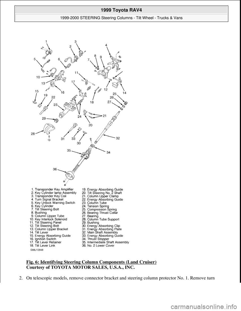
Fig. 6: Identifying Steering Column Components (Land Cruiser)
Courtesy of TOYOTA MOTOR SALES, U.S.A., INC.
2. On telescopic models, remove connector bracket and steerin
g column protector No. 1. Remove turn
1999 Toyota RAV4
1999-2000 STEERING Steering Columns - Tilt Wheel - Trucks & Vans
Microsoft
Sunday, November 22, 2009 10:34:02 AMPage 13 © 2005 Mitchell Repair Information Company, LLC.
Page 1268 of 1632
signal bracket. Using hexagon wrench, remove support stopper bolt, spring and stopper No. 1. Remove 2
tilt steering bolts and power tilt motor. Remove 2 "E" rings. Remove 2 support stopper bolt bushings from
power tilt motor.
3. On models without telescopic steering, using 1/8-5/32" (3-4 mm) drill, drill out tapered head column
bracket bolts. Use screw extractor to remove bolts. Remove column upper bracket and column upper
clamp.
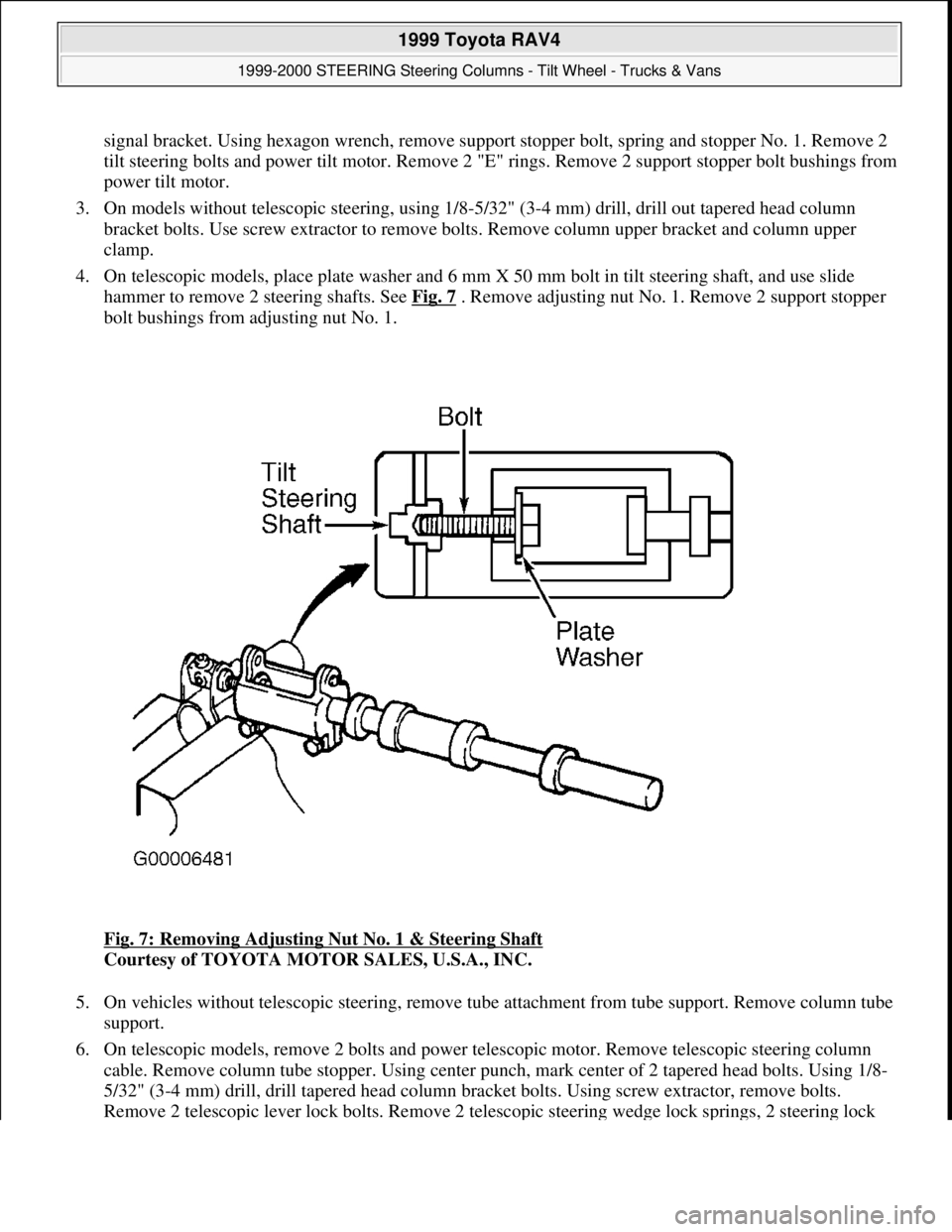
4. On telescopic models, place plate washer and 6 mm X 50 mm bolt in tilt steering shaft, and use slide
hammer to remove 2 steering shafts. See Fig. 7
. Remove adjusting nut No. 1. Remove 2 support stopper
bolt bushings from adjusting nut No. 1.
Fig. 7: Removing Adjusting Nut No. 1 & Steering Shaft
Courtesy of TOYOTA MOTOR SALES, U.S.A., INC.
5. On vehicles without telescopic steering, remove tube attachment from tube support. Remove column tube
support.
6. On telescopic models, remove 2 bolts and power telescopic motor. Remove telescopic steering column
cable. Remove column tube stopper. Using center punch, mark center of 2 tapered head bolts. Using 1/8-
5/32" (3-4 mm) drill, drill tapered head column bracket bolts. Using screw extractor, remove bolts.
Remove 2 telescopic lever lock bolts. Remove 2 telescopic steerin
g wedge lock springs, 2 steering lock
1999 Toyota RAV4
1999-2000 STEERING Steering Columns - Tilt Wheel - Trucks & Vans
Microsoft
Sunday, November 22, 2009 10:34:03 AMPage 14 © 2005 Mitchell Repair Information Company, LLC.
Page 1269 of 1632
wedges, column upper bracket and column upper clamp. Remove column tube support.
7. On all models, remove energy absorbing clip. Remove energy absorbing plates and guides. On vehicles
without telescopic steering, and remove 4 tension springs.
8. On vehicles without telescopic steering, remove spring nut and tilt lever. Remove 2 bushings from
column upper tube. Remove tilt lever link.
9. On models without telescopic steering, remove column upper tube with main shaft assembly. Remove tilt
lever retainer. Remove main shaft assembly. Remove turn signal bracket. Remove tilt steering pawl.
Remove bushing.
10. On models with telescopic steering, remove telescopic steering slider support. Remove telescopic steering
bushing and slider. Remove steering column bracket spacer. Remove nut, 4 energy absorber cushions, 2
bearings and telescopic steering screw.
11. On vehicles without telescopic steering, remove snap ring. Using hexagon wrench, remove 2 tilt steering
bolts and column upper tube sub-assembly. Remove column upper tube assembly from column tube.
Remove 2 support stopper bolt bushing from column upper tube assembly. Remove 3 bushings from
column tube.
12. On vehicles with telescopic steering, compress compression spring. Using snap ring expander, remove
snap ring. Remove shaft assembly from column upper tube. Remove compression spring and bearing
thrust collar from shaft assembly.
Inspection
Check that steering lock mechanism operates properly. Check bearing rotation condition of main shaft assembly
and check for abnormal noise. Repair or replace components as necessary.
Reassembly
To reassemble, reverse disassembly procedure. Align bushing tab with hole of column tube. Apply
molybdenum disulfide lithium base grease to tilt lever assembly, lock bolt, main shaft and steering column bolt
pivot points. Tighten bolts and nuts to specification. See TORQUE SPECIFICATIONS .
Disassembly (RAV4)
1. Mark sliding yoke and main shaft. Remove sliding yoke. SeeFig. 8 . Using 1/8-5/32" (3-4 mm) drill, drill
tapered head column bracket bolts. Using screw extractor, remove bracket bolts. Remove column upper
bracket and column upper clamp. Remove tube attachment from column tube support. Remove column
tube support.
2. Remove energy absorbing clip. Remove energy absorbing plate, energy absorbing guide and break-away
capsule. Turn lock nut clockwise, and then remove it. Remove No. 1 tilt lever lock bolt, tilt lever
assembly and tilt sub lever. Remove break-away bracket.
3. Using snap ring pliers, remove snap ring from column shaft assembly. Using extension bar and hammer,
top out shaft assembly. Using screwdriver, tap out bushing. Using snap ring pliers, remove snap ring from
shaft assembl
y.
1999 Toyota RAV4
1999-2000 STEERING Steering Columns - Tilt Wheel - Trucks & Vans
Microsoft
Sunday, November 22, 2009 10:34:03 AMPage 15 © 2005 Mitchell Repair Information Company, LLC.
Page 1270 of 1632
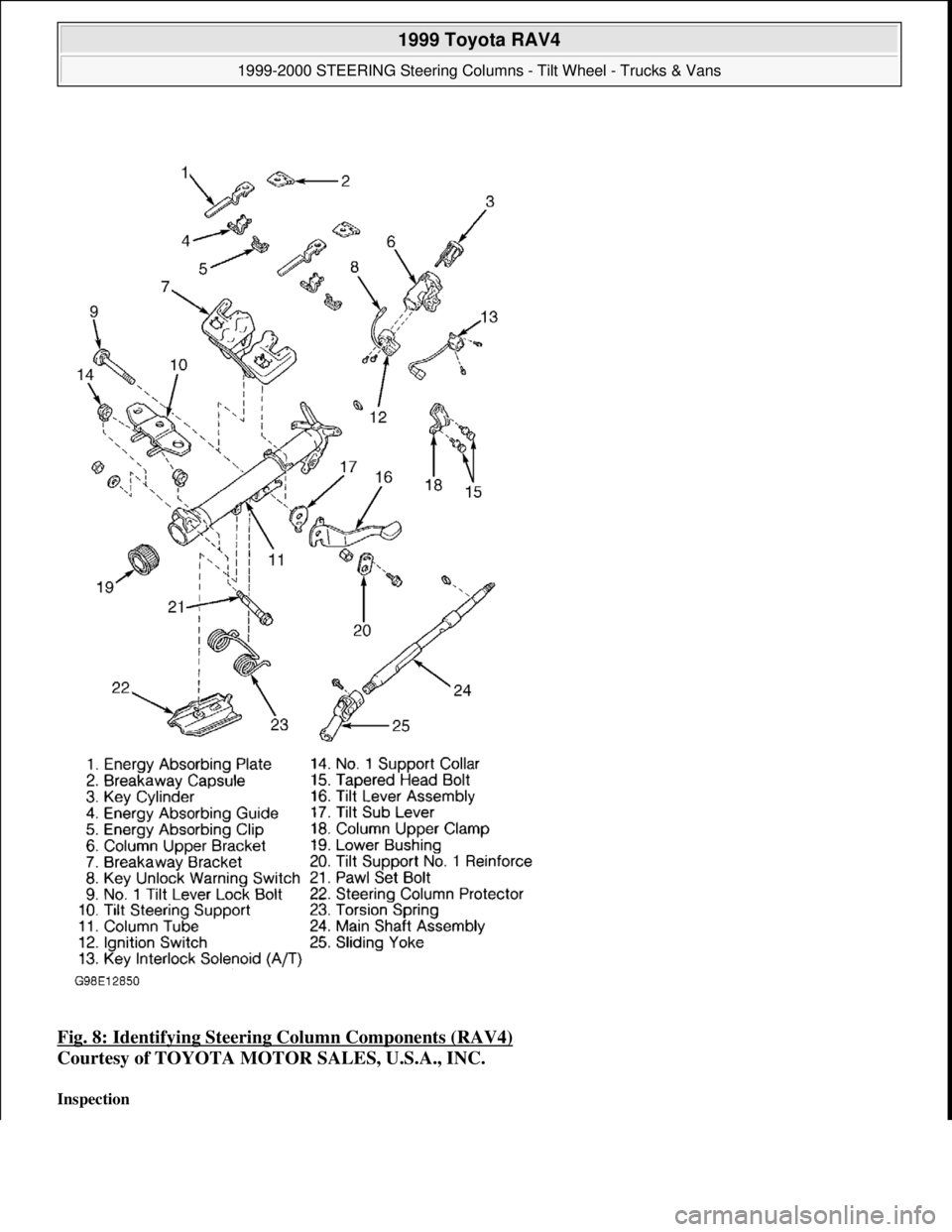
Fig. 8: Identifying Steering Column Components (RAV4)
Courtesy of TOYOTA MOTOR SALES, U.S.A., INC.
Inspection
1999 Toyota RAV4
1999-2000 STEERING Steering Columns - Tilt Wheel - Trucks & Vans
Microsoft
Sunday, November 22, 2009 10:34:03 AMPage 16 © 2005 Mitchell Repair Information Company, LLC.