TOYOTA RAV4 1996 Service Repair Manual
Manufacturer: TOYOTA, Model Year: 1996, Model line: RAV4, Model: TOYOTA RAV4 1996Pages: 1632, PDF Size: 41.64 MB
Page 441 of 1632
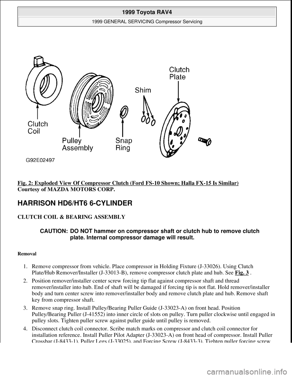
Fig. 2: Exploded View Of Compressor Clutch (Ford FS-10 Shown; Halla FX-15 Is Similar)
Courtesy of MAZDA MOTORS CORP.
HARRISON HD6/HT6 6-CYLINDER
CLUTCH COIL & BEARING ASSEMBLY
Removal
1. Remove compressor from vehicle. Place compressor in Holding Fixture (J-33026). Using Clutch
Plate/Hub Remover/Installer (J-33013-B), remove compressor clutch plate and hub. See Fig. 3
.
2. Position remover/installer center screw forcing tip flat against compressor shaft and thread
remover/installer into hub. End of shaft will be damaged if forcing tip is not flat. Hold remover/installer
body and turn center screw into remover/installer body and remove clutch plate and hub. Remove shaft
key from compressor shaft.
3. Remove snap ring. Install Pulley/Bearing Puller Guide (J-33023-A) on front head. Position
Pulley/Bearing Puller (J-41552) into inner circle of slots on pulley. Turn puller clockwise until engaged in
pulley slots. Tighten puller screw against puller guide until pulley is removed.
4. Disconnect clutch coil connector. Scribe match marks on compressor and clutch coil connector for
installation reference. Install Puller Pilot Adapter (J-33023-A) on front head of compressor. Install Puller
Crossbar (J-8433-1), Puller Legs (J-33025), and Forcing Screw (J-8433-3). Tighten puller forcing screw
CAUTION: DO NOT hammer on compressor shaft or clutch hub to remove clutch
plate. Internal compressor damage will result.
1999 Toyota RAV4
1999 GENERAL SERVICING Compressor Servicing
Microsoft
Sunday, November 22, 2009 10:31:50 AMPage 4 © 2005 Mitchell Repair Information Company, LLC.
Page 442 of 1632
against pilot adapter and remove clutch coil. See Fig. 3.
Installation
1. Align clutch reference marks made during removal. Position Clutch Coil Installer (J-33024) over internal
opening of clutch coil housing and align with front head of compressor. Position Puller Crossbar (J-8433-
1) and Through-Bolts (J-33026) so Forcing Screw (J-8433-3) is centered in clutch coil installer center
hole. Ensure through-bolts are fully threaded into holding fixture.
2. Tighten forcing screw against installer to press clutch coil onto compressor front head. Ensure clutch coil
and installer stay aligned during installation. When clutch coil is fully seated on front head, stake front
head and clutch coil. Using a 1/8" (3.2 mm) punch, stake clutch coil inner ring in 3 places, 120 degrees
apart. Stake size should be 1/2 the area of punch tip and 0.010-0.015" (0.28-0.38 mm) deep.
3. Position Pulley/Bearing Installer (J-33017) and Pulley/Bearing Puller Guide (J-33023-A) over inner race
of pulley bearing. Position Puller Crossbar (J-8433-1) and Through-Bolts (J-33026) so Forcing Screw (J-
8433-3) is centered over puller guide. Ensure through-bolts are fully threaded into holding fixture.
4. Tighten forcing screw against puller guide to press pulley and bearing assembly onto front head of
compressor. Ensure puller guide and front head of compressor stay aligned during installation. Install
snap ring.
5. Install shaft key into clutch plate and hub. Ensure shaft key protrudes about 1/8" (3.2 mm) out of keyway.
Ensure friction surfaces of clutch plate and pulley are clean. Ensure shaft key and keyway in hub are
aligned and position clutch plate and hub onto compressor shaft.
6. Install Clutch Plate/Hub Remover/Installer (J-33013-B) with forcing screw in installation position. Body
of remover/installer should be backed off from hub enough to allow forcing screw to be threaded onto
compressor shaft.
7. Hold forcing screw and tighten installer body to press hub onto compressor shaft. Before pressing clutch
plate and hub to final position, remove installer and ensure shaft key is still in keyway. Continue pressing
clutch plate and hub until air gap between friction surfaces is 0.020-0.030" (0.51-0.76 mm).
SHAFT SEAL
Removal
1. Discharge A/C system, using approved refrigerant recovery/recycling equipment. Loosen and reposition
compressor in mounting bracket. Remove clutch plate and hub assembly. See CLUTCH COIL &
BEARING ASSEMBLY . See Fig. 3 .
2. Remove shaft seal snap ring. Thoroughly clean all surfaces around seal including inside of compressor
neck and exposed parts of seal, snap rin
g groove, and compressor shaft. Insert shaft Seal CAUTION: When installing clutch plate and hub, if forcing screw is fully threaded
onto end of compressor shaft or installer body is held and forcing screw is
rotated, the shaft key will bind and break the clutch hub.
NOTE: It is not necessary to replace compressor shaft seal because of small amounts
of refrigerant oil seepage. Replace compressor shaft seal when a refrigerant
leak is detected.
1999 Toyota RAV4
1999 GENERAL SERVICING Compressor Servicing
Microsoft
Sunday, November 22, 2009 10:31:50 AMPage 5 © 2005 Mitchell Repair Information Company, LLC.
Page 443 of 1632
Remover/Installer (J-23128-A) into shaft seal. Hand-tighten seal remover/installer handle clockwise to
seat inside seal. Remove shaft seal by turning and pulling seal remover/installer.
3. Using "O" Ring Remover (J-9553-01), remove "O" ring. Ensure shaft and inside of compressor neck are
clean and free of foreign material. Thoroughly clean "O" ring groove in front head.
Installation
1. Lubricate new "O" ring with refrigerant oil and install using "O" Ring Installer (J-33011). Expand seal
using shaft "O" ring installer. Insert installer into compressor until it bottoms. Move slide on installer
downward until "O" ring is released into lower groove. Rotate installer to seat "O" ring and remove
installer.
2. Lubricate shaft seal with refrigerant oil. Install shaft seal onto Seal Remover/Installer (J-23128-A). Install
shaft seal so flared side of lip seal is installed toward compressor. Install Seal Protector (J-34614) into
shaft seal lip and position seal protector over compressor shaft.
3. Push shaft seal into compressor using a rotary motion until seal bottoms. Use care to not move "O" ring.
Remove installer. Install new snap ring with flat side against seal. Using seal remover/installer, push snap
ring into snap ring groove. Clean excess refrigerant oil from compressor shaft and neck. Install clutch
plate and hub assembl
y onto compressor shaft. See CLUTCH COIL & BEARING ASSEMBLY.
1999 Toyota RAV4
1999 GENERAL SERVICING Compressor Servicing
Microsoft
Sunday, November 22, 2009 10:31:50 AMPage 6 © 2005 Mitchell Repair Information Company, LLC.
Page 444 of 1632
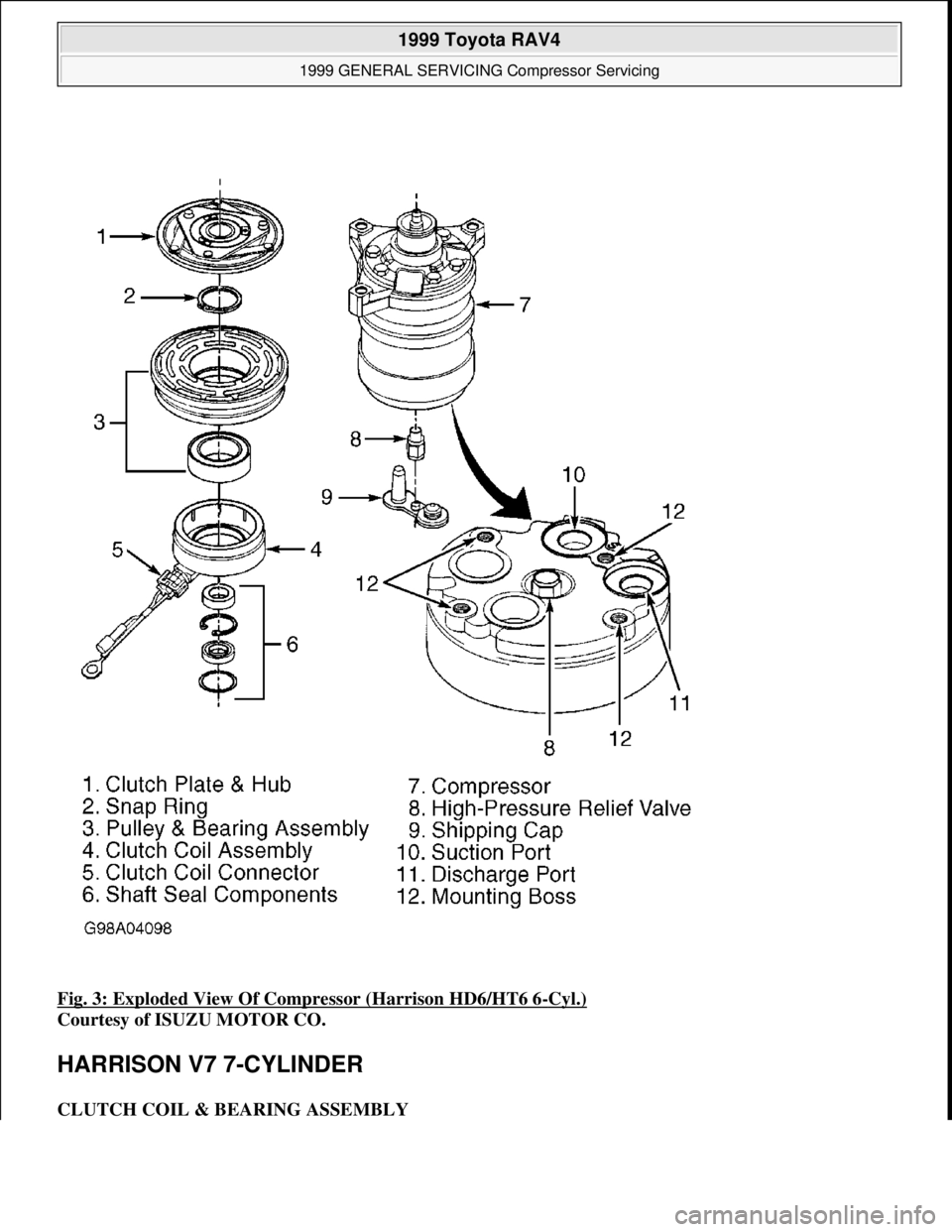
Fig. 3: Exploded View Of Compressor (Harrison HD6/HT6 6-Cyl.)
Courtesy of ISUZU MOTOR CO.
HARRISON V7 7-CYLINDER
CLUTCH COIL & BEARING ASSEMBLY
1999 Toyota RAV4
1999 GENERAL SERVICING Compressor Servicing
Microsoft
Sunday, November 22, 2009 10:31:50 AMPage 7 © 2005 Mitchell Repair Information Company, LLC.
Page 445 of 1632
Removal
1. Remove compressor from vehicle. Place compressor in Holding Fixture (J-41790). Use Clutch Plate
Spanner (J-33027) to hold clutch plate. Remove compressor shaft nut.
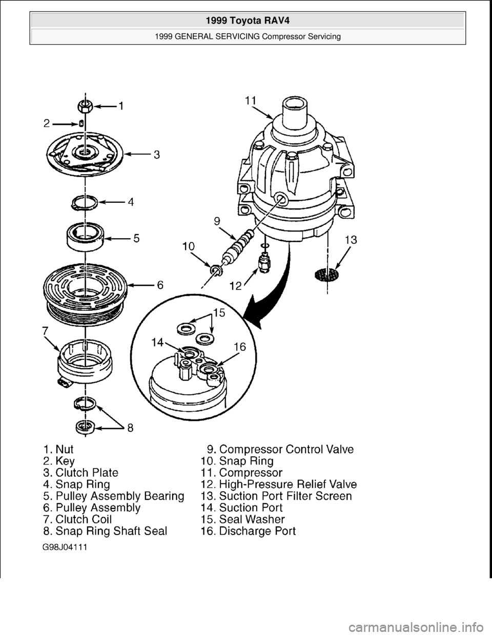
2. Use Clutch Plate Remover/Installer (J-33013-B) to remove compressor clutch plate and hub. See Fig. 4
.
Hold remover body and turn center screw into remover body to remove clutch plate and hub. Ensure
forcing tip on remover/installer center screw is flat or end of shaft/axial plate will be damaged. Remove
key from compressor shaft.
3. Remove snap ring. Install Puller Pilot/Guide (J-33023-A) on front head. Position Pulley and Bearing
Puller (J-41552) into inner circle of slots on pulley. Turn puller clockwise in slots to engage puller tangs
with pulley. Tighten puller forcing screw against puller pilot/guide and remove pulley.
4. Disconnect clutch coil lead. Scribe marks on compressor and clutch coil for installation reference. Install
Puller Pilot/Guide (J-33023-A) on front head. Remove clutch coil using puller pilot/guide and 2-jaw
puller. Position puller
jaws under edge of clutch coil. CAUTION: DO NOT hammer on compressor shaft or clutch hub to remove clutch
plate. Internal compressor damage will result.
1999 Toyota RAV4
1999 GENERAL SERVICING Compressor Servicing
Microsoft
Sunday, November 22, 2009 10:31:50 AMPage 8 © 2005 Mitchell Repair Information Company, LLC.
Page 446 of 1632
1999 Toyota RAV4
1999 GENERAL SERVICING Compressor Servicing
Microsoft
Sunday, November 22, 2009 10:31:50 AMPage 9 © 2005 Mitchell Repair Information Company, LLC.
Page 447 of 1632
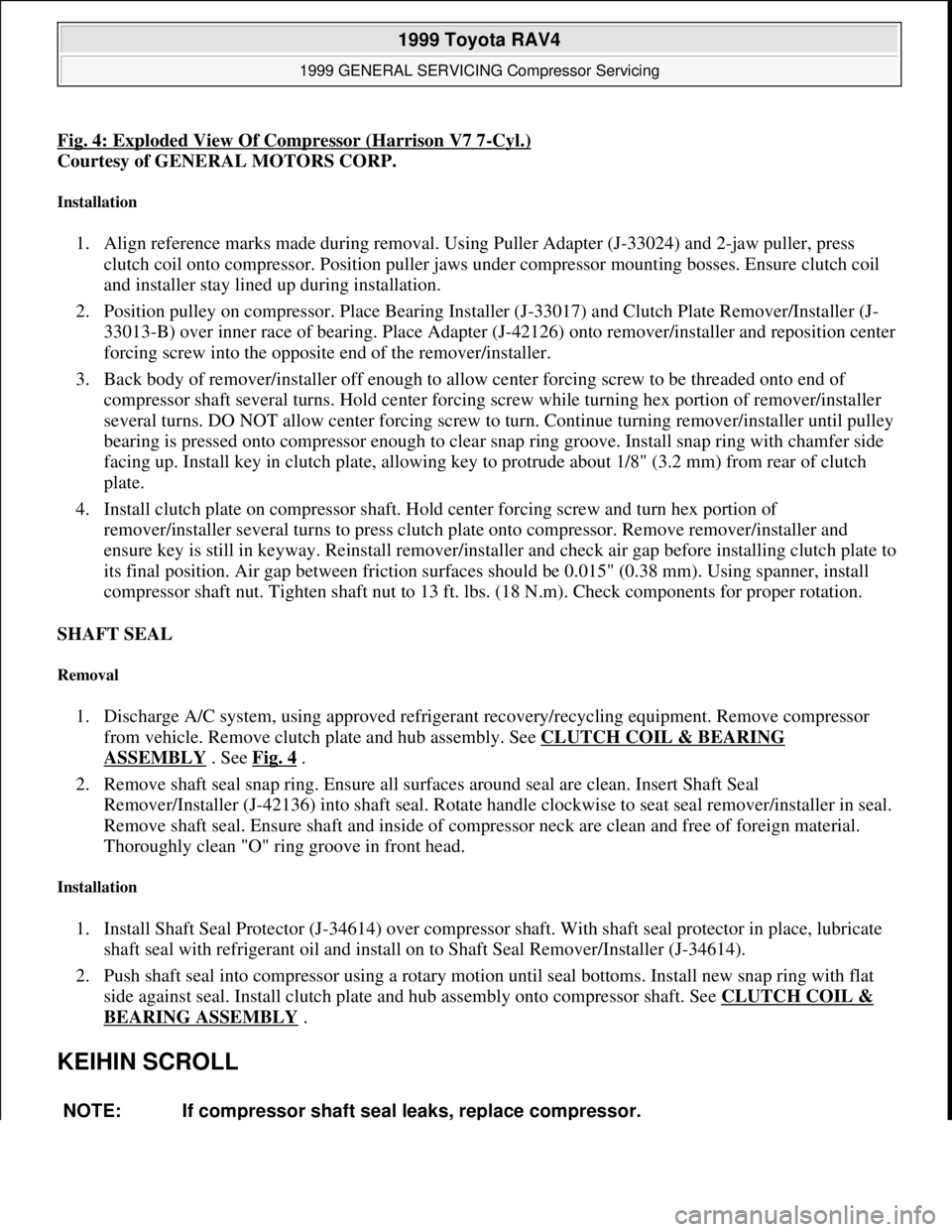
Fig. 4: Exploded View Of Compressor (Harrison V7 7-Cyl.)
Courtesy of GENERAL MOTORS CORP.
Installation
1. Align reference marks made during removal. Using Puller Adapter (J-33024) and 2-jaw puller, press
clutch coil onto compressor. Position puller jaws under compressor mounting bosses. Ensure clutch coil
and installer stay lined up during installation.
2. Position pulley on compressor. Place Bearing Installer (J-33017) and Clutch Plate Remover/Installer (J-
33013-B) over inner race of bearing. Place Adapter (J-42126) onto remover/installer and reposition center
forcing screw into the opposite end of the remover/installer.
3. Back body of remover/installer off enough to allow center forcing screw to be threaded onto end of
compressor shaft several turns. Hold center forcing screw while turning hex portion of remover/installer
several turns. DO NOT allow center forcing screw to turn. Continue turning remover/installer until pulley
bearing is pressed onto compressor enough to clear snap ring groove. Install snap ring with chamfer side
facing up. Install key in clutch plate, allowing key to protrude about 1/8" (3.2 mm) from rear of clutch
plate.
4. Install clutch plate on compressor shaft. Hold center forcing screw and turn hex portion of
remover/installer several turns to press clutch plate onto compressor. Remove remover/installer and
ensure key is still in keyway. Reinstall remover/installer and check air gap before installing clutch plate to
its final position. Air gap between friction surfaces should be 0.015" (0.38 mm). Using spanner, install
compressor shaft nut. Tighten shaft nut to 13 ft. lbs. (18 N.m). Check components for proper rotation.
SHAFT SEAL
Removal
1. Discharge A/C system, using approved refrigerant recovery/recycling equipment. Remove compressor
from vehicle. Remove clutch plate and hub assembly. See CLUTCH COIL & BEARING
ASSEMBLY . See Fig. 4 .
2. Remove shaft seal snap ring. Ensure all surfaces around seal are clean. Insert Shaft Seal
Remover/Installer (J-42136) into shaft seal. Rotate handle clockwise to seat seal remover/installer in seal.
Remove shaft seal. Ensure shaft and inside of compressor neck are clean and free of foreign material.
Thoroughly clean "O" ring groove in front head.
Installation
1. Install Shaft Seal Protector (J-34614) over compressor shaft. With shaft seal protector in place, lubricate
shaft seal with refrigerant oil and install on to Shaft Seal Remover/Installer (J-34614).
2. Push shaft seal into compressor using a rotary motion until seal bottoms. Install new snap ring with flat
side against seal. Install clutch plate and hub assembly onto compressor shaft. See CLUTCH COIL &
BEARING ASSEMBLY .
KEIHIN SCROLL
NOTE: If compressor shaft seal leaks, replace compressor.
1999 Toyota RAV4
1999 GENERAL SERVICING Compressor Servicing
Microsoft
Sunday, November 22, 2009 10:31:50 AMPage 10 © 2005 Mitchell Repair Information Company, LLC.
Page 448 of 1632
CLUTCH COIL
Removal
Hold clutch plate and remove shaft bolt. Remove clutch plate and adjustment shim(s). See Fig. 5 . Remove
pulley snap ring and discard. Position universal 2-jaw puller to back of pulley and Driver Adapter (07947-
6340300) to center of pulley. If puller jaws are located on belt area, pulley will be damaged. Remove pulley.
Remove clutch coil snap ring and discard. Disconnect clutch coil wiring harness and remove clutch coil.
Installation
1. Install clutch coil in reverse order of removal. Ensure wire side is facing down and pin on clutch coil boss
is aligned with hole in compressor housing. Ensure snap ring is properly seated. Properly route and
connect clutch coil wiring harness.
2. Install shims the same thickness as originally removed. Position pulley over clutch coil. Using Hub Guide
(07965-6920500), press pulley onto compressor boss. Maximum press load is 5690 psi (400 kg/cm
2 ) or
882 lbs. (400 kg). If pulley does not press on straight, remove pulley and inspect pulley and compressor
boss for damage or burrs.
3. Hold clutch plate and tighten shaft nut to 13 ft. lbs. (18 N.m). Ensure air gap between clutch plate and
pulley is 0.014-0.026" (0.35-0.65 mm). If air gap is incorrect, add or remove shim(s) as necessary.
1999 Toyota RAV4
1999 GENERAL SERVICING Compressor Servicing
Microsoft
Sunday, November 22, 2009 10:31:50 AMPage 11 © 2005 Mitchell Repair Information Company, LLC.
Page 449 of 1632
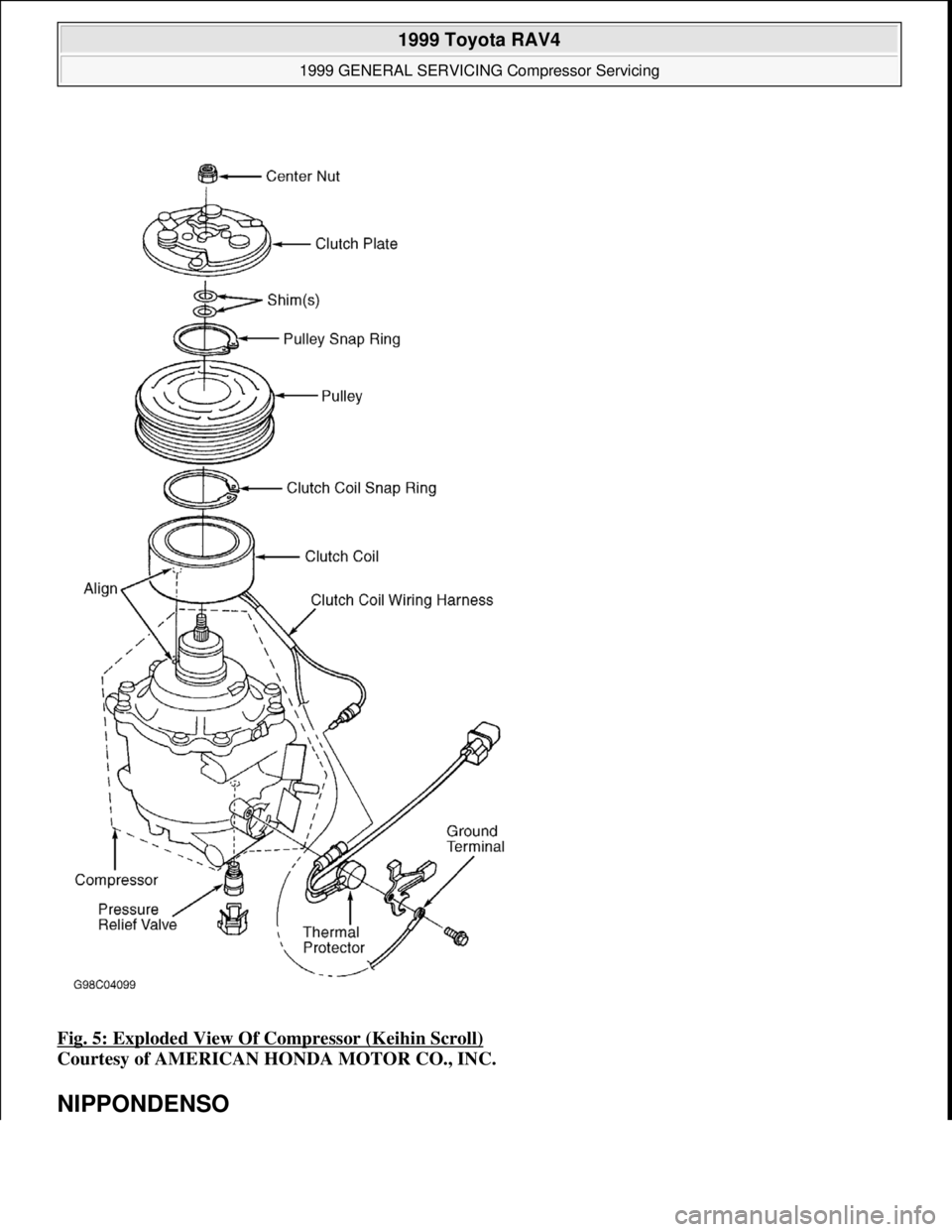
Fig. 5: Exploded View Of Compressor (Keihin Scroll)
Courtesy of AMERICAN HONDA MOTOR CO., INC.
NIPPONDENSO
1999 Toyota RAV4
1999 GENERAL SERVICING Compressor Servicing
Microsoft
Sunday, November 22, 2009 10:31:50 AMPage 12 © 2005 Mitchell Repair Information Company, LLC.
Page 450 of 1632
CLUTCH COIL
Removal (Acura, BMW, Honda & Isuzu)
On Acura and Honda, using Clutch Plate Holder (J-37872), hold clutch plate stationary and remove compressor
shaft bolt. On BMW, using Clutch Plate Holder (64-5-090), hold clutch plate stationary and remove compressor
shaft bolt. On all models, remove clutch plate and shims. Remove snap ring and pulley. Remove clutch coil
wiring harness from compressor. Remove snap ring and clutch coil. See Fig. 6
, Fig. 7 or Fig. 8 .
Installation
1. To install, reverse removal procedure. Use NEW snap rings. Ensure snap rings are installed with beveled
side facing out and fully seated in snap ring groove. Install clutch coil with wire facing downward. Apply
thread lock to compressor shaft bolt. Tighten shaft bolt to 117 INCH lbs. (13 N.m).
2. On Acura and Honda, ensure air gap between clutch plate and pulley is 0.014-0.026" (0.36-0.66 mm). On
BMW, ensure air gap between clutch plate and pulley is 0.020-0.031" (0.50-0.80 mm). If air gap is
incorrect, add or remove shim(s) as necessary.
Removal (Mazda Miata)
1. Hold clutch plate using Clutch Holder (00007-10331) and remove shaft bolt. Install Clutch Disc Remover
(4992-02-020) and remove clutch plate and shim(s). See Fig. 6
, Fig. 7 or Fig. 8 .
2. Remove pulley snap ring and tap pulley (with bearing) off of compressor. Remove screw for clutch coil
lead. Mark position of clutch coil. Remove clutch coil snap ring and clutch coil.
Installation
To install, reverse removal procedure. Tighten shaft bolt to 97-142 INCH lbs. (11-16 N.m). Ensure pulley-to-
clutch plate clearance is 0.014-0.025" (0.35-0.64 mm). If clearance is incorrect, add or remove shim(s) as
necessary.
Removal (Mercedes-Benz & Mitsubishi)
1. Hold clutch plate stationary. Remove clutch plate center bolt and clutch plate. If clutch plate cannot be
removed by hand, tighten an 8-mm or 10-mm bolt into clutch plate center bolt hole to remove clutch
plate.
2. Remove shim(s) and pulley snap ring from compressor shaft. Tap pulley using a plastic hammer and
remove pulley from compressor shaft. See Fig. 6
, Fig. 7 or Fig. 8 . Remove retaining screw for clutch
coil lead. Remove clutch coil snap ring and clutch coil.
Installation
1. To install, reverse removal procedure. Ensure clutch coil pin is aligned with hole in compressor housing. NOTE: Due to the variety of clutch and shaft seal configurations, obtain appropriate
A/C compressor service tools for compressor being serviced. Land Rover and
Jaguar compressor servicing procedures are not available from manufacturer.
1999 Toyota RAV4
1999 GENERAL SERVICING Compressor Servicing
Microsoft
Sunday, November 22, 2009 10:31:50 AMPage 13 © 2005 Mitchell Repair Information Company, LLC.