TOYOTA RAV4 1996 Service Repair Manual
Manufacturer: TOYOTA, Model Year: 1996, Model line: RAV4, Model: TOYOTA RAV4 1996Pages: 1632, PDF Size: 41.64 MB
Page 851 of 1632
1999 HEATER SYSTEMS
RAV4, Tacoma & 4Runner
DESCRIPTION
Major components of the heater system are a heater core, control panel, blower motor, water valve, hoses,
control cables and air ducts. 4Runner may be equipped with a dual heater system with separate controls for
front and rear. Rear temperature and blower controls are located in the console between front seats.
OPERATION
BLOWER SWITCH
Switch controls blower motor speed through blower resistor. Blower speed is adjusted by control lever, knob or
push button.
CONTROL PANEL
Temperature and mode knobs or levers are connected by cable to heater coolant valve and air doors. All models
have a fresh/recirculation lever to provide choice of outside air or recirculated inside air.
HEATER RELAY
A heater (or main) relay controls current through system. For location of heater (main) relay, see WIRING
DIAGRAMS .
ADJUSTMENTS
AIR INLET DAMPER CABLE
Set air inlet damper and control lever to fresh (recirculated on RAV4) air position. Remove cable retaining clip,
and ensure damper and cable are in full fresh (recirculated on RAV4) air position. Install control cable clip.
Check operation of air intake damper.
AIRFLOW MODE DAMPER CABLE WARNING:To avoid injury from accidental air bag deployment, read and carefully
follow all SERVICE PRECAUTIONS and DISABLING & ACTIVATING AIR
BAG SYSTEM procedures in AIR BAG SYSTEM SAFETY article in
GENERAL SERVICING.
CAUTION: When battery is disconnected, radio will go into anti-theft protection mode.
Obtain radio anti-theft protection code from owner prior to servicing
vehicle.
1999 Toyota RAV4
1999 HEATER SYSTEMS RAV4, Tacoma & 4Runner
1999 Toyota RAV4
1999 HEATER SYSTEMS RAV4, Tacoma & 4Runner
Microsoft
Sunday, November 22, 2009 10:30:50 AMPage 1 © 2005 Mitchell Repair Information Company, LLC.
Microsoft
Sunday, November 22, 2009 10:30:55 AMPage 1 © 2005 Mitchell Repair Information Company, LLC.
Page 852 of 1632
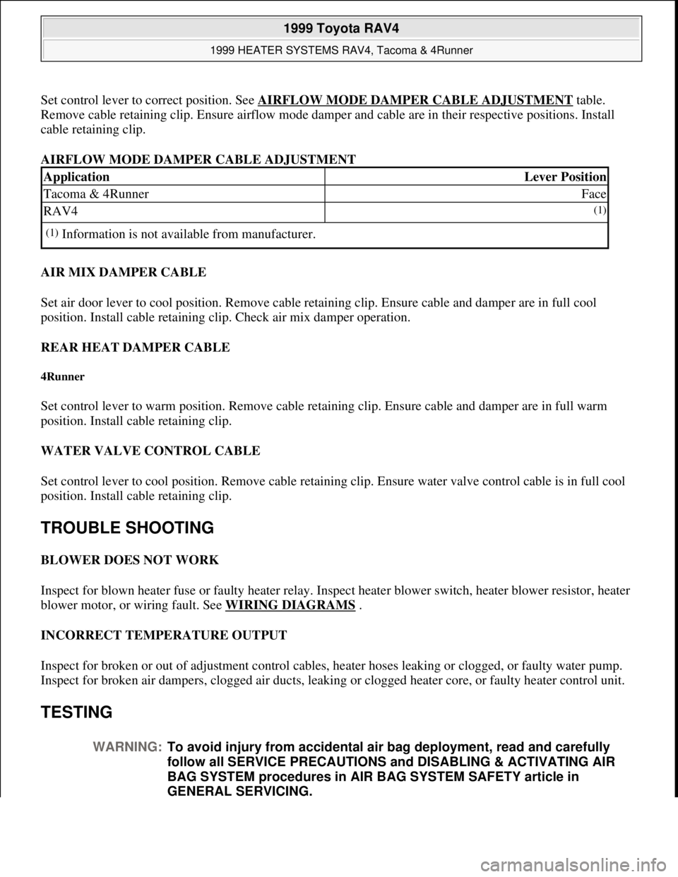
Set control lever to correct position. See AIRFLOW MODE DAMPER CABLE ADJUSTMENTtable.
Remove cable retaining clip. Ensure airflow mode damper and cable are in their respective positions. Install
cable retaining clip.
AIRFLOW MODE DAMPER CABLE ADJUSTMENT
AIR MIX DAMPER CABLE
Set air door lever to cool position. Remove cable retaining clip. Ensure cable and damper are in full cool
position. Install cable retaining clip. Check air mix damper operation.
REAR HEAT DAMPER CABLE
4Runner
Set control lever to warm position. Remove cable retaining clip. Ensure cable and damper are in full warm
position. Install cable retaining clip.
WATER VALVE CONTROL CABLE
Set control lever to cool position. Remove cable retaining clip. Ensure water valve control cable is in full cool
position. Install cable retaining clip.
TROUBLE SHOOTING
BLOWER DOES NOT WORK
Inspect for blown heater fuse or faulty heater relay. Inspect heater blower switch, heater blower resistor, heater
blower motor, or wiring fault. See WIRING DIAGRAMS
.
INCORRECT TEMPERATURE OUTPUT
Inspect for broken or out of adjustment control cables, heater hoses leaking or clogged, or faulty water pump.
Inspect for broken air dampers, clogged air ducts, leaking or clogged heater core, or faulty heater control unit.
TESTING
ApplicationLever Position
Tacoma & 4RunnerFace
RAV4(1)
(1)Information is not available from manufacturer.
WARNING:To avoid injury from accidental air bag deployment, read and carefully
follow all SERVICE PRECAUTIONS and DISABLING & ACTIVATING AIR
BAG SYSTEM procedures in AIR BAG SYSTEM SAFETY article in
GENERAL SERVICING.
1999 Toyota RAV4
1999 HEATER SYSTEMS RAV4, Tacoma & 4Runner
Microsoft
Sunday, November 22, 2009 10:30:50 AMPage 2 © 2005 Mitchell Repair Information Company, LLC.
Page 853 of 1632
BLOWER MOTOR
Unplug blower motor connector. See WIRING DIAGRAMS
. Replace motor if it does not operate smoothly.
Perform the following test procedures:
RAV4 & Tacoma
Apply battery voltage to motor side terminal No. 1 and ground terminal No. 2.
4Runner (Front Blower)
Apply battery voltage to motor side terminal No. 2 and ground terminal No. 1.
4Runner (Rear Blower)
Apply battery voltage to motor side terminal No. 1 and ground terminal No. 2.
BLOWER RESISTOR
RAV4 & Tacoma
Unplug resistor connector. See Fig. 1 . See WIRING DIAGRAMS . Test for continuity between blower
resistor terminals No. 1, 2, 3 and 4. If continuity does not exist between any terminals, replace resistor.
4Runner (Front)
Unplug resistor connector. Using a DVOM, measure resistance between indicated terminals. See Fig. 1 . See
WIRING DIAGRAMS
. See BLOWER RESISTOR (4RUNNER) table. If resistance is not as specified,
replace resistor.
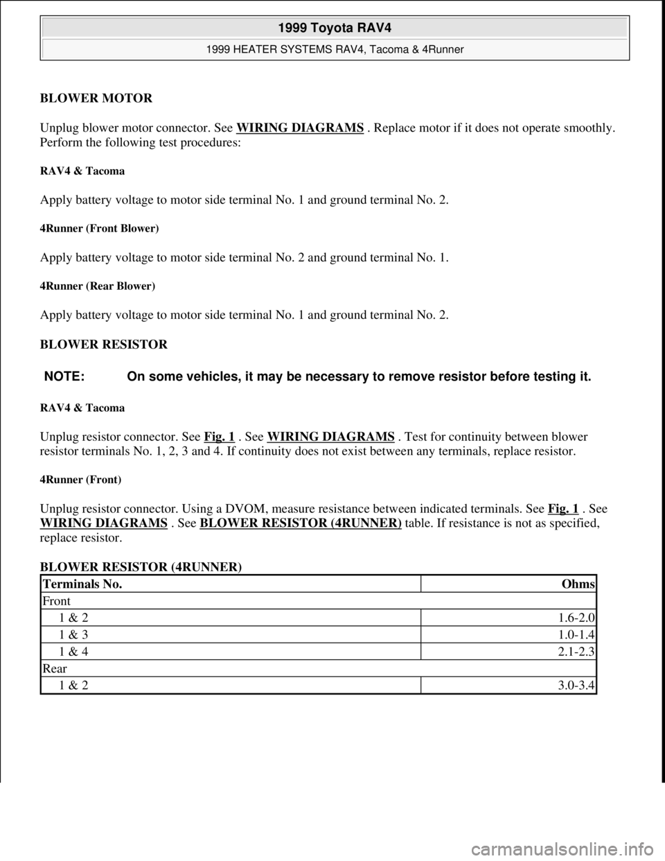
BLOWER RESISTOR (4RUNNER) NOTE: On some vehicles, it may be necessary to remove resistor before testing it.
Terminals No.Ohms
Front
1 & 21.6-2.0
1 & 31.0-1.4
1 & 42.1-2.3
Rear
1 & 23.0-3.4
1999 Toyota RAV4
1999 HEATER SYSTEMS RAV4, Tacoma & 4Runner
Microsoft
Sunday, November 22, 2009 10:30:50 AMPage 3 © 2005 Mitchell Repair Information Company, LLC.
Page 854 of 1632
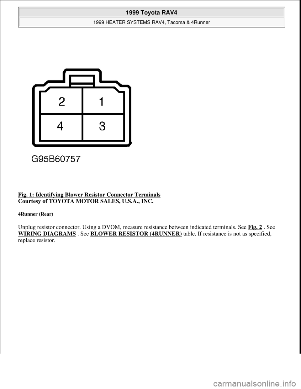
Fig. 1: Identifying Blower Resistor Connector Terminals
Courtesy of TOYOTA MOTOR SALES, U.S.A., INC.
4Runner (Rear)
Unplug resistor connector. Using a DVOM, measure resistance between indicated terminals. See Fig. 2 . See
WIRING DIAGRAMS
. See BLOWER RESISTOR (4RUNNER) table. If resistance is not as specified,
replace resistor.
1999 Toyota RAV4
1999 HEATER SYSTEMS RAV4, Tacoma & 4Runner
Microsoft
Sunday, November 22, 2009 10:30:50 AMPage 4 © 2005 Mitchell Repair Information Company, LLC.
Page 855 of 1632
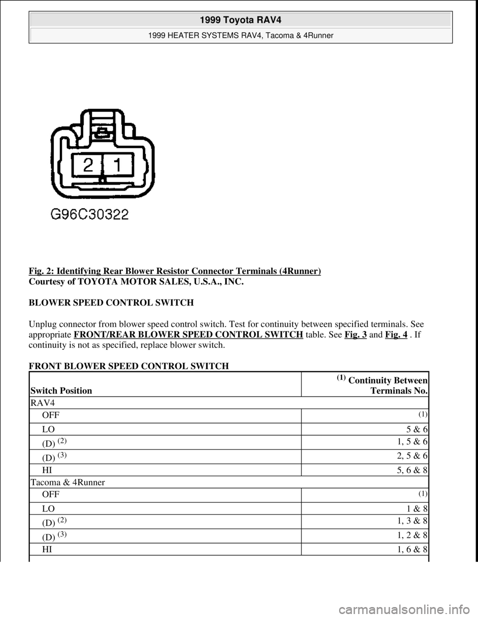
Fig. 2: Identifying Rear Blower Resistor Connector Terminals (4Runner)
Courtesy of TOYOTA MOTOR SALES, U.S.A., INC.
BLOWER SPEED CONTROL SWITCH
Unplug connector from blower speed control switch. Test for continuity between specified terminals. See
appropriate FRONT/REAR BLOWER SPEED CONTROL SWITCH
table. See Fig. 3 and Fig. 4 . If
continuity is not as specified, replace blower switch.
FRONT BLOWER SPEED CONTROL SWITCH
Switch Position
(1) Continuity Between
Terminals No.
RAV4
OFF(1)
LO5 & 6
(D) (2) 1, 5 & 6
(D) (3) 2, 5 & 6
HI5, 6 & 8
Tacoma & 4Runner
OFF(1)
LO1 & 8
(D) (2) 1, 3 & 8
(D) (3) 1, 2 & 8
HI1, 6 & 8
1999 Toyota RAV4
1999 HEATER SYSTEMS RAV4, Tacoma & 4Runner
Microsoft
Sunday, November 22, 2009 10:30:50 AMPage 5 © 2005 Mitchell Repair Information Company, LLC.
Page 856 of 1632
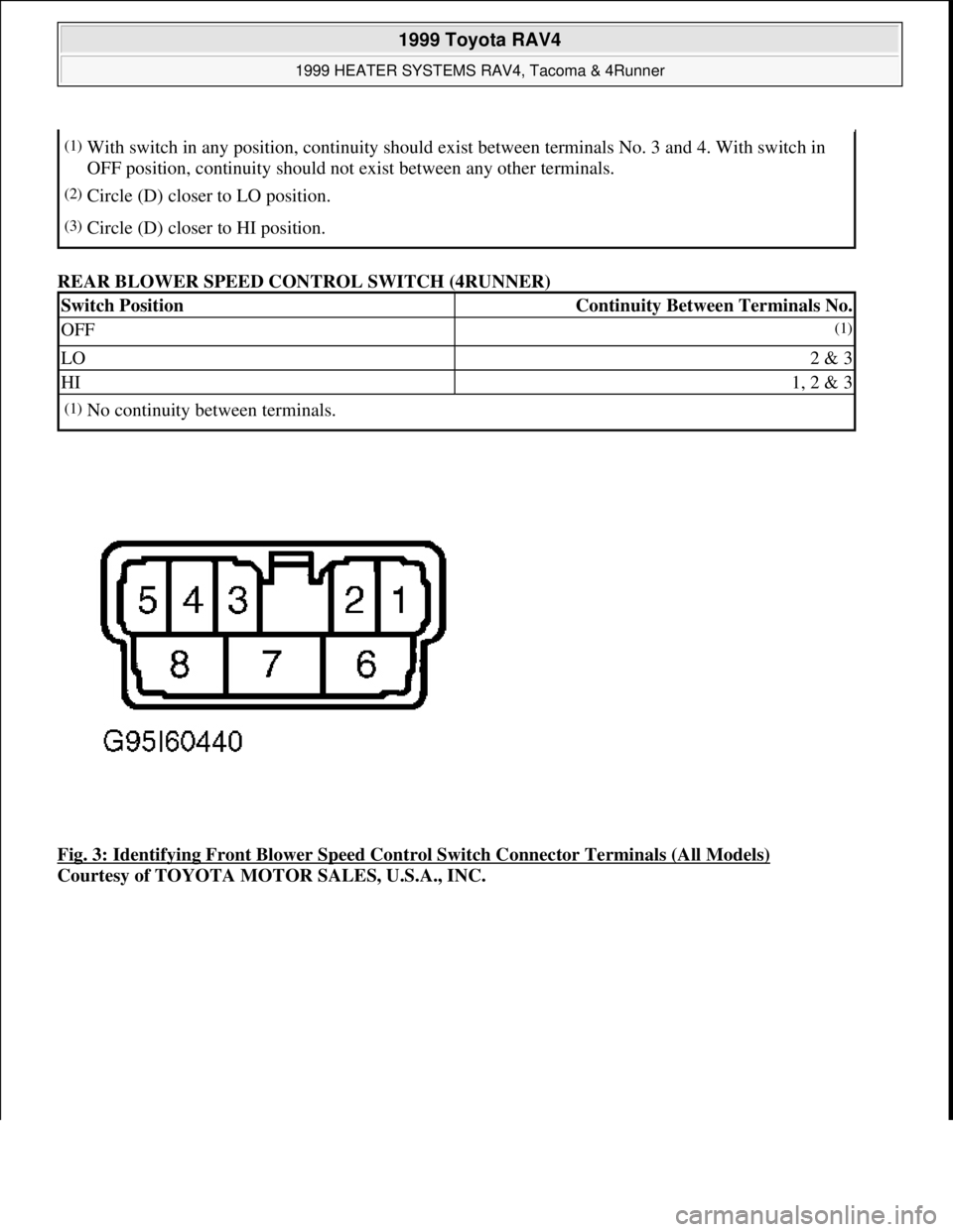
REAR BLOWER SPEED CONTROL SWITCH (4RUNNER)
Fig. 3: Identifying Front Blower Speed Control Switch Connector Terminals (All Models)
Courtesy of TOYOTA MOTOR SALES, U.S.A., INC.
(1)With switch in any position, continuity should exist between terminals No. 3 and 4. With switch in
OFF position, continuity should not exist between any other terminals.
(2)Circle (D) closer to LO position.
(3)Circle (D) closer to HI position.
Switch PositionContinuity Between Terminals No.
OFF(1)
LO2 & 3
HI1, 2 & 3
(1)No continuity between terminals.
1999 Toyota RAV4
1999 HEATER SYSTEMS RAV4, Tacoma & 4Runner
Microsoft
Sunday, November 22, 2009 10:30:50 AMPage 6 © 2005 Mitchell Repair Information Company, LLC.
Page 857 of 1632
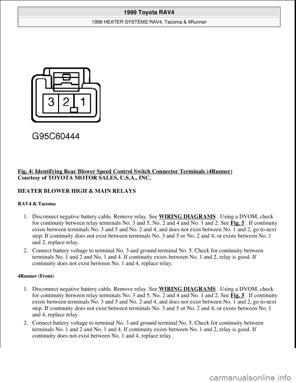
Fig. 4: Identifying Rear Blower Speed Control Switch Connector Terminals (4Runner)
Courtesy of TOYOTA MOTOR SALES, U.S.A., INC.
HEATER BLOWER HIGH & MAIN RELAYS
RAV4 & Tacoma
1. Disconnect negative battery cable. Remove relay. See WIRING DIAGRAMS . Using a DVOM, check
for continuity between relay terminals No. 3 and 5, No. 2 and 4 and No. 1 and 2. See Fig. 5
. If continuity
exists between terminals No. 3 and 5 and No. 2 and 4, and does not exist between No. 1 and 2, go to next
step. If continuity does not exist between terminals No. 3 and 5 or No. 2 and 4, or exists between No. 1
and 2, replace relay.
2. Connect battery voltage to terminal No. 3 and ground terminal No. 5. Check for continuity between
terminals No. 1 and 2 and No. 1 and 4. If continuity exists between No. 1 and 2, relay is good. If
continuity does not exist between No. 1 and 4, replace relay.
4Runner (Front)
1. Disconnect negative battery cable. Remove relay. See WIRING DIAGRAMS . Using a DVOM, check
for continuity between relay terminals No. 3 and 5, No. 2 and 4 and No. 1 and 2. See Fig. 5
. If continuity
exists between terminals No. 3 and 5 and No. 2 and 4, and does not exist between No. 1 and 2, go to next
step. If continuity does not exist between terminals No. 3 and 5 or No. 2 and 4, or exists between No. 1
and 4, replace relay.
2. Connect battery voltage to terminal No. 3 and ground terminal No. 5. Check for continuity between
terminals No. 1 and 2 and No. 1 and 4. If continuity exists between No. 1 and 2, relay is good. If
continuity does not exist between No. 1 and 4, replace relay.
1999 Toyota RAV4
1999 HEATER SYSTEMS RAV4, Tacoma & 4Runner
Microsoft
Sunday, November 22, 2009 10:30:50 AMPage 7 © 2005 Mitchell Repair Information Company, LLC.
Page 858 of 1632
4Runner (Rear)
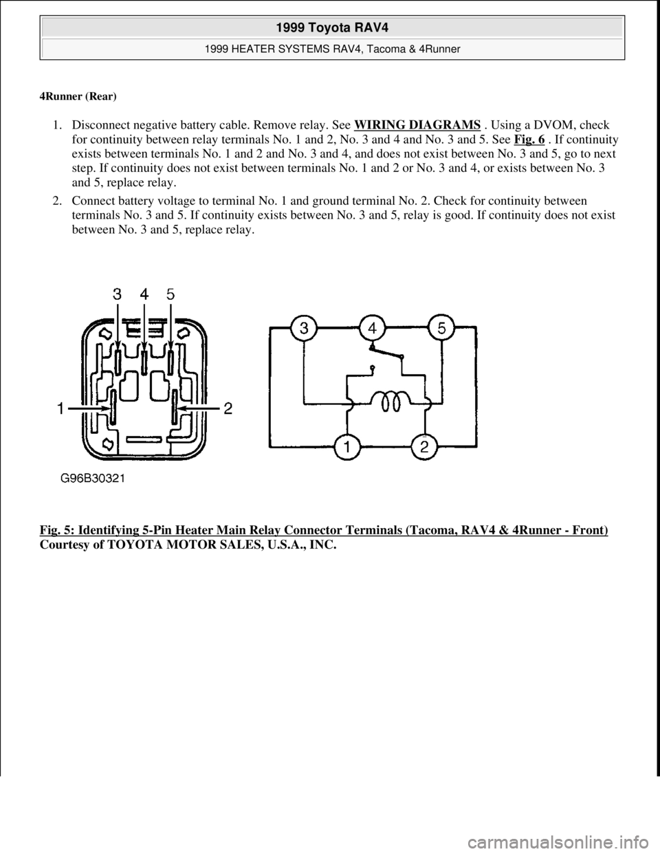
1. Disconnect negative battery cable. Remove relay. See WIRING DIAGRAMS . Using a DVOM, check
for continuity between relay terminals No. 1 and 2, No. 3 and 4 and No. 3 and 5. See Fig. 6
. If continuity
exists between terminals No. 1 and 2 and No. 3 and 4, and does not exist between No. 3 and 5, go to next
step. If continuity does not exist between terminals No. 1 and 2 or No. 3 and 4, or exists between No. 3
and 5, replace relay.
2. Connect battery voltage to terminal No. 1 and ground terminal No. 2. Check for continuity between
terminals No. 3 and 5. If continuity exists between No. 3 and 5, relay is good. If continuity does not exist
between No. 3 and 5, replace relay.
Fig. 5: Identifying 5
-Pin Heater Main Relay Connector Terminals (Tacoma, RAV4 & 4Runner - Front)
Courtesy of TOYOTA MOTOR SALES, U.S.A., INC.
1999 Toyota RAV4
1999 HEATER SYSTEMS RAV4, Tacoma & 4Runner
Microsoft
Sunday, November 22, 2009 10:30:50 AMPage 8 © 2005 Mitchell Repair Information Company, LLC.
Page 859 of 1632
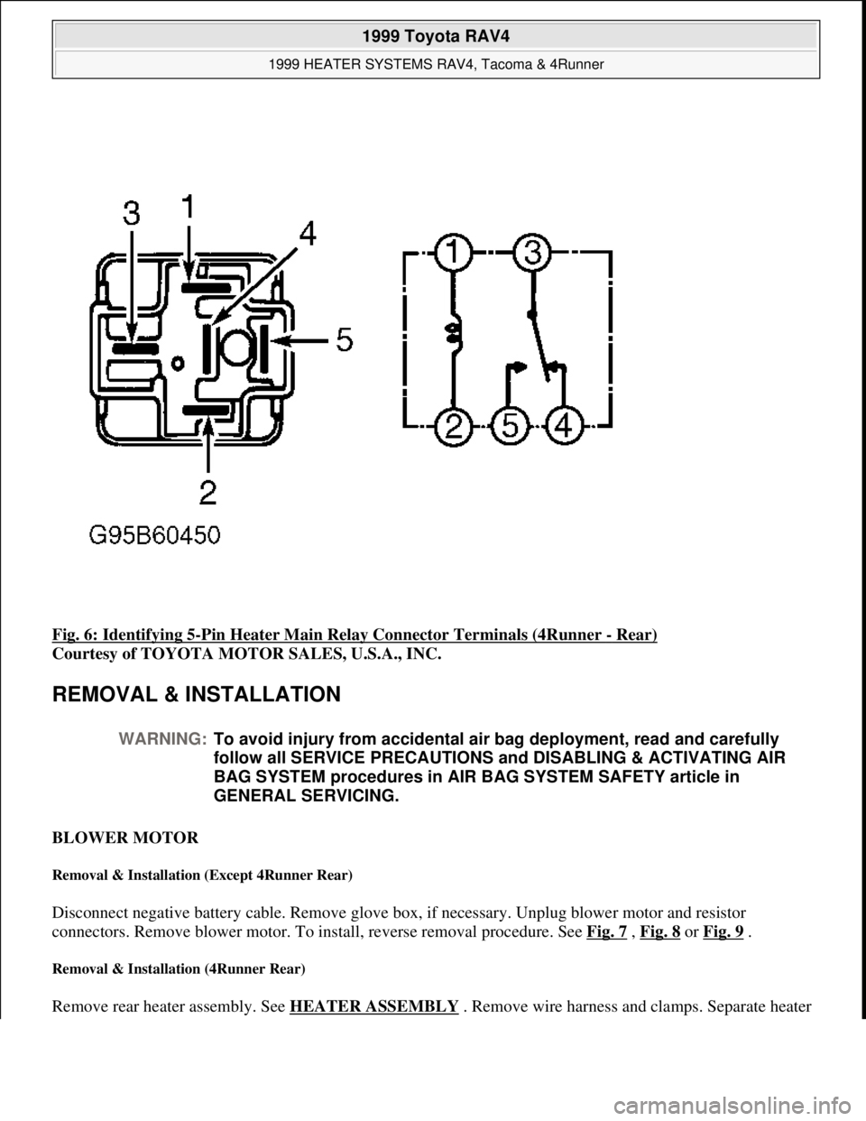
Fig. 6: Identifying 5-Pin Heater Main Relay Connector Terminals (4Runner - Rear)
Courtesy of TOYOTA MOTOR SALES, U.S.A., INC.
REMOVAL & INSTALLATION
BLOWER MOTOR
Removal & Installation (Except 4Runner Rear)
Disconnect negative battery cable. Remove glove box, if necessary. Unplug blower motor and resistor
connectors. Remove blower motor. To install, reverse removal procedure. See Fig. 7
, Fig. 8 or Fig. 9 .
Removal & Installation (4Runner Rear)
Remove rear heater assembly. See HEATER ASSEMBLY. Remove wire harness and clamps. Separate heater
WARNING:To avoid injury from accidental air bag deployment, read and carefully
follow all SERVICE PRECAUTIONS and DISABLING & ACTIVATING AIR
BAG SYSTEM procedures in AIR BAG SYSTEM SAFETY article in
GENERAL SERVICING.
1999 Toyota RAV4
1999 HEATER SYSTEMS RAV4, Tacoma & 4Runner
Microsoft
Sunday, November 22, 2009 10:30:50 AMPage 9 © 2005 Mitchell Repair Information Company, LLC.
Page 860 of 1632
case and remove blower motor. To install, reverse removal procedure. See Fig. 10 .
HEATER ASSEMBLY
Removal & Installation (All Except 4Runner Rear)
1. Remove A/C cooling unit (if equipped). See appropriate MANUAL A/C-HEATER SYSTEMS article.
Drain cooling system. Disconnect hoses from heater core. Remove grommets from hoses. Remove
instrument panel (if required).
2. Disconnect control cables from heater assembly. Remove defroster nozzle and heater duct. Remove
heater unit. See Fig. 7
, Fig. 8 or Fig. 9 . Remove screws, clamps and heater core. To reassemble and
install, reverse removal procedure.
Removal & Installation (4Runner Rear)
1. Drain cooling system. Remove front seats and center console box. Roll floor carpet back and disconnect
water hoses. Remove heater duct.
2. Disconnect control cable and remove heater control assembly. Remove heater unit. See Fig. 10
. Remove
wire harness and clamps. Separate heater case and heater core. To reassemble and install, reverse removal
procedure. NOTE: Tacoma and 4Runner may require removal of instrument panel and/or glove box
components. See INSTRUMENT PANEL
.
1999 Toyota RAV4
1999 HEATER SYSTEMS RAV4, Tacoma & 4Runner
Microsoft
Sunday, November 22, 2009 10:30:50 AMPage 10 © 2005 Mitchell Repair Information Company, LLC.