TOYOTA RAV4 1996 Service Repair Manual
Manufacturer: TOYOTA, Model Year: 1996, Model line: RAV4, Model: TOYOTA RAV4 1996Pages: 1632, PDF Size: 41.64 MB
Page 881 of 1632
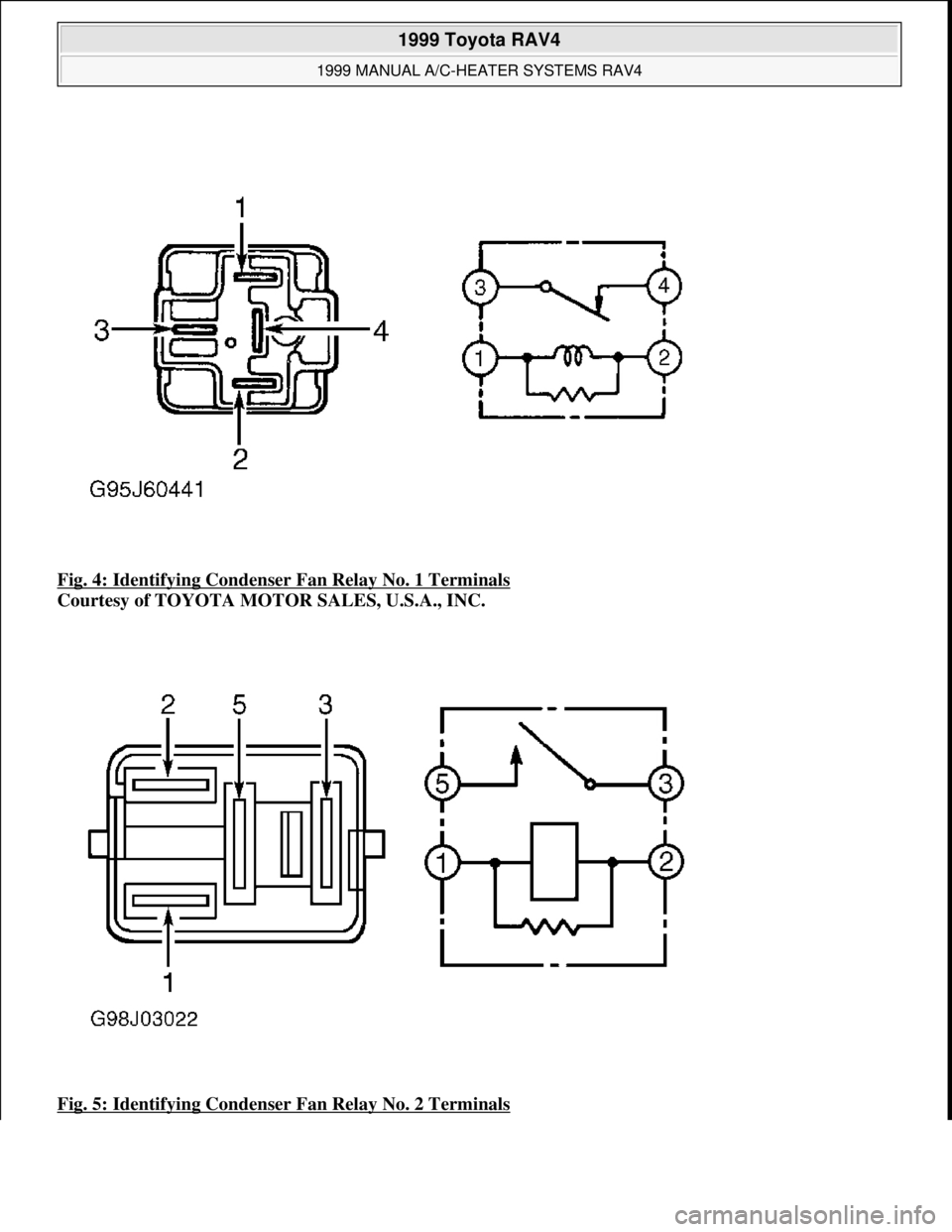
Fig. 4: Identifying Condenser Fan Relay No. 1 Terminals
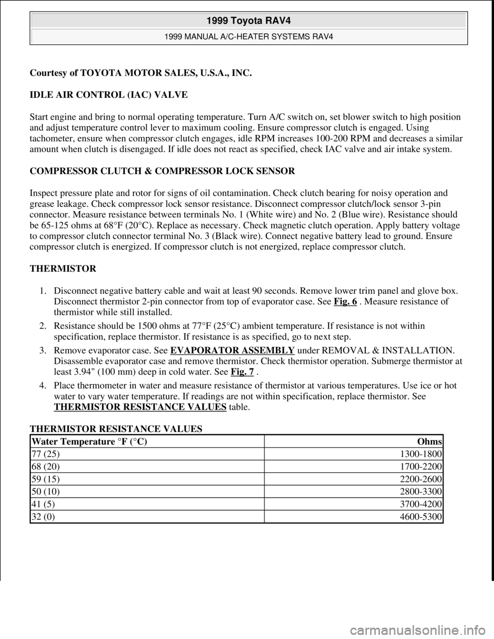
Courtesy of TOYOTA MOTOR SALES, U.S.A., INC.
Fig. 5: Identifying Condenser Fan Relay No. 2 Terminals
1999 Toyota RAV4
1999 MANUAL A/C-HEATER SYSTEMS RAV4
Microsoft
Sunday, November 22, 2009 10:29:28 AMPage 8 © 2005 Mitchell Repair Information Company, LLC.
Page 882 of 1632
Courtesy of TOYOTA MOTOR SALES, U.S.A., INC.
IDLE AIR CONTROL (IAC) VALVE
Start engine and bring to normal operating temperature. Turn A/C switch on, set blower switch to high position
and adjust temperature control lever to maximum cooling. Ensure compressor clutch is engaged. Using
tachometer, ensure when compressor clutch engages, idle RPM increases 100-200 RPM and decreases a similar
amount when clutch is disengaged. If idle does not react as specified, check IAC valve and air intake system.
COMPRESSOR CLUTCH & COMPRESSOR LOCK SENSOR
Inspect pressure plate and rotor for signs of oil contamination. Check clutch bearing for noisy operation and
grease leakage. Check compressor lock sensor resistance. Disconnect compressor clutch/lock sensor 3-pin
connector. Measure resistance between terminals No. 1 (White wire) and No. 2 (Blue wire). Resistance should
be 65-125 ohms at 68°F (20°C). Replace as necessary. Check magnetic clutch operation. Apply battery voltage
to compressor clutch connector terminal No. 3 (Black wire). Connect negative battery lead to ground. Ensure
compressor clutch is energized. If compressor clutch is not energized, replace compressor clutch.
THERMISTOR
1. Disconnect negative battery cable and wait at least 90 seconds. Remove lower trim panel and glove box.
Disconnect thermistor 2-pin connector from top of evaporator case. See Fig. 6
. Measure resistance of
thermistor while still installed.
2. Resistance should be 1500 ohms at 77°F (25°C) ambient temperature. If resistance is not within
specification, replace thermistor. If resistance is as specified, go to next step.
3. Remove evaporator case. See EVAPORATOR ASSEMBLY
under REMOVAL & INSTALLATION.
Disassemble evaporator case and remove thermistor. Check thermistor operation. Submerge thermistor at
least 3.94" (100 mm) deep in cold water. See Fig. 7
.
4. Place thermometer in water and measure resistance of thermistor at various temperatures. Use ice or hot
water to vary water temperature. If readings are not within specification, replace thermistor. See
THERMISTOR RESISTANCE VALUES
table.
THERMISTOR RESISTANCE VALUES
Water Temperature °F (°C)Ohms
77 (25)1300-1800
68 (20)1700-2200
59 (15)2200-2600
50 (10)2800-3300
41 (5)3700-4200
32 (0)4600-5300
1999 Toyota RAV4
1999 MANUAL A/C-HEATER SYSTEMS RAV4
Microsoft
Sunday, November 22, 2009 10:29:28 AMPage 9 © 2005 Mitchell Repair Information Company, LLC.
Page 883 of 1632
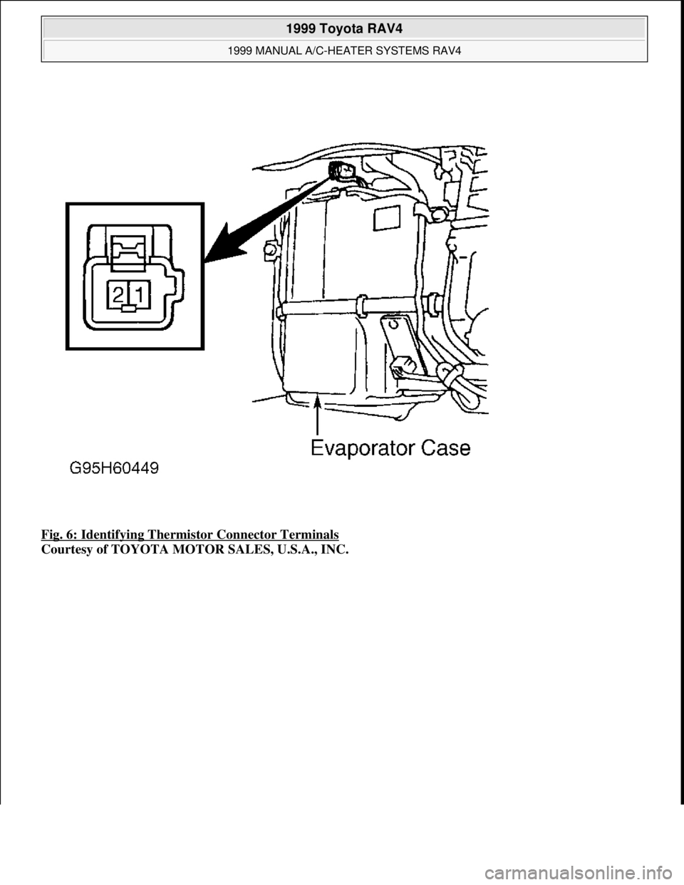
Fig. 6: Identifying Thermistor Connector Terminals
Courtesy of TOYOTA MOTOR SALES, U.S.A., INC.
1999 Toyota RAV4
1999 MANUAL A/C-HEATER SYSTEMS RAV4
Microsoft
Sunday, November 22, 2009 10:29:28 AMPage 10 © 2005 Mitchell Repair Information Company, LLC.
Page 884 of 1632
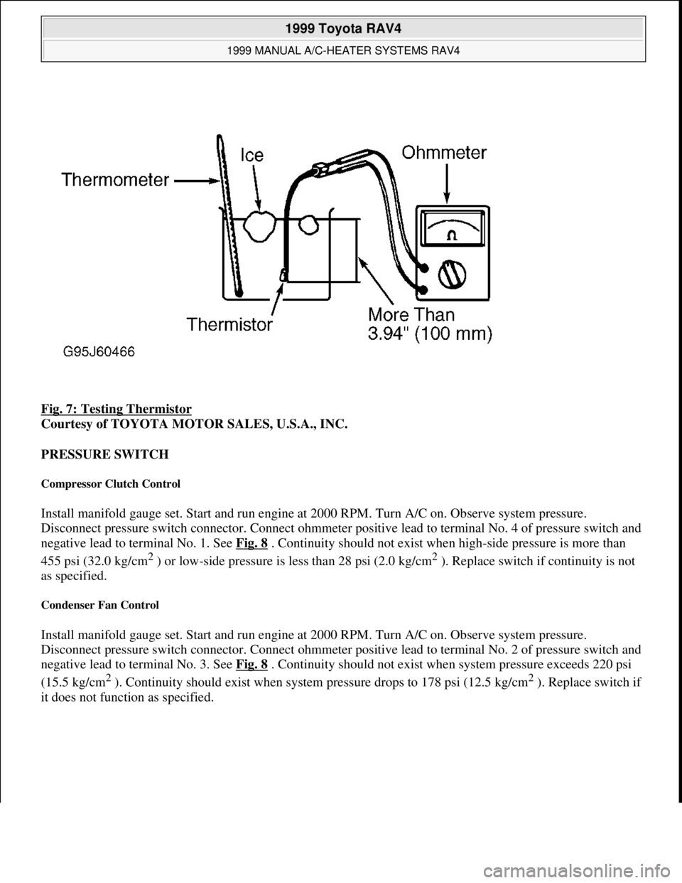
Fig. 7: Testing Thermistor
Courtesy of TOYOTA MOTOR SALES, U.S.A., INC.
PRESSURE SWITCH
Compressor Clutch Control
Install manifold gauge set. Start and run engine at 2000 RPM. Turn A/C on. Observe system pressure.
Disconnect pressure switch connector. Connect ohmmeter positive lead to terminal No. 4 of pressure switch and
negative lead to terminal No. 1. See Fig. 8
. Continuity should not exist when high-side pressure is more than
455 psi (32.0 kg/cm
2 ) or low-side pressure is less than 28 psi (2.0 kg/cm2 ). Replace switch if continuity is not
as specified.
Condenser Fan Control
Install manifold gauge set. Start and run engine at 2000 RPM. Turn A/C on. Observe system pressure.
Disconnect pressure switch connector. Connect ohmmeter positive lead to terminal No. 2 of pressure switch and
negative lead to terminal No. 3. See Fig. 8
. Continuity should not exist when system pressure exceeds 220 psi
(15.5 kg/cm
2 ). Continuity should exist when system pressure drops to 178 psi (12.5 kg/cm2 ). Replace switch if
it does not function as specified.
1999 Toyota RAV4
1999 MANUAL A/C-HEATER SYSTEMS RAV4
Microsoft
Sunday, November 22, 2009 10:29:28 AMPage 11 © 2005 Mitchell Repair Information Company, LLC.
Page 885 of 1632
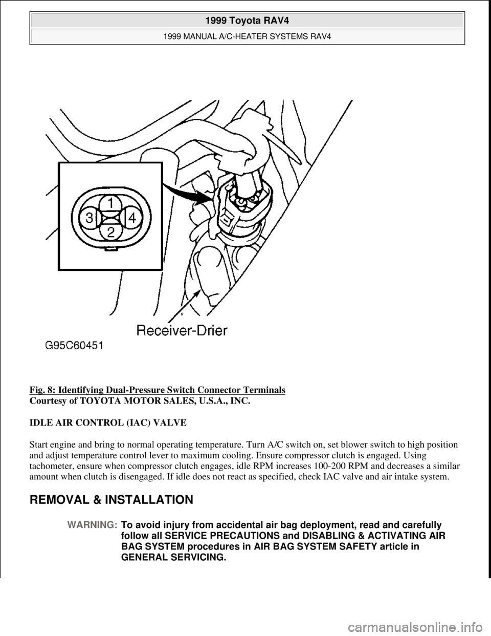
Fig. 8: Identifying Dual-Pressure Switch Connector Terminals
Courtesy of TOYOTA MOTOR SALES, U.S.A., INC.
IDLE AIR CONTROL (IAC) VALVE
Start engine and bring to normal operating temperature. Turn A/C switch on, set blower switch to high position
and adjust temperature control lever to maximum cooling. Ensure compressor clutch is engaged. Using
tachometer, ensure when compressor clutch engages, idle RPM increases 100-200 RPM and decreases a similar
amount when clutch is disengaged. If idle does not react as specified, check IAC valve and air intake system.
REMOVAL & INSTALLATION
WARNING:To avoid injury from accidental air bag deployment, read and carefully
follow all SERVICE PRECAUTIONS and DISABLING & ACTIVATING AIR
BAG SYSTEM procedures in AIR BAG SYSTEM SAFETY article in
GENERAL SERVICING.
1999 Toyota RAV4
1999 MANUAL A/C-HEATER SYSTEMS RAV4
Microsoft
Sunday, November 22, 2009 10:29:28 AMPage 12 © 2005 Mitchell Repair Information Company, LLC.
Page 886 of 1632
COMPRESSOR
Removal
1. If possible, run A/C system for 10 minutes. Disconnect negative battery cable and wait at least 90
seconds. Disconnect compressor clutch electrical connector.
2. Discharge A/C system, using approved refrigerant recovery/recycling equipment. Disconnect compressor
hoses and cap hose ends to keep moisture out of system. Remove right side engine undercover, if
necessary. Loosen lock nut and belt adjusting bolt at generator. Remove compressor drive belt. Remove
compressor mounting bolts. Remove compressor.
Installation
To install, reverse removal procedure. Tighten mounting bolts and compressor hoses to specification. See
TORQUE SPECIFICATIONS
. Evacuate, charge and leak test system.
CONDENSER
Removal
Discharge A/C system, using approved refrigerant recovery/recycling equipment. Disconnect negative battery
cable and wait at least 90 seconds. Disconnect A/C lines from condenser. Plug all openings. Remove 2
condenser mounting bolts and condenser.
Installation
To install, reverse removal procedure. Tighten condenser hoses to specification. See TORQUE
SPECIFICATIONS . If installing a new condenser, add 1.4 ounces of refrigerant oil to compressor. Evacuate,
charge and leak test system.
EVAPORATOR ASSEMBLY
Removal
Disconnect negative battery cable and wait at least 90 seconds. Discharge A/C system, using approved
refrigerant recovery/recycling equipment. Remove glove box assembly. Using knife, cut off glove compartment
reinforcement. Disconnect inlet lines, outlet lines and grommets from evaporator. Plug openings. Disconnect
electrical leads from evaporator. Remove 3 attaching screws and 3 nuts. Remove evaporator assembly.
Disassembly
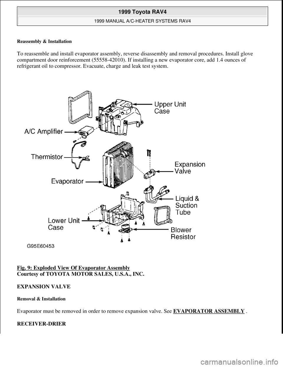
Remove blower resistor and A/C amplifier. Release spring clips holding covers together. Remove 4 screws at
case joints. Separate upper and lower cases from evaporator core. Remove evaporator from lower case. Remove
thermistor and expansion valve. See Fig. 9
. NOTE: For removal and installation procedures not covered in this article, see HEATER
SYSTEMS - RAV4, TACOMA & 4RUNNER article.
1999 Toyota RAV4
1999 MANUAL A/C-HEATER SYSTEMS RAV4
Microsoft
Sunday, November 22, 2009 10:29:28 AMPage 13 © 2005 Mitchell Repair Information Company, LLC.
Page 887 of 1632
Reassembly & Installation
To reassemble and install evaporator assembly, reverse disassembly and removal procedures. Install glove
compartment door reinforcement (55558-42010). If installing a new evaporator core, add 1.4 ounces of
refrigerant oil to compressor. Evacuate, charge and leak test system.
Fig. 9: Exploded View Of Evaporator Assembly
Courtesy of TOYOTA MOTOR SALES, U.S.A., INC.
EXPANSION VALVE
Removal & Installation
Evaporator must be removed in order to remove expansion valve. See EVAPORATOR ASSEMBLY .
RECEIVER-DRIER
1999 Toyota RAV4
1999 MANUAL A/C-HEATER SYSTEMS RAV4
Microsoft
Sunday, November 22, 2009 10:29:28 AMPage 14 © 2005 Mitchell Repair Information Company, LLC.
Page 888 of 1632
Removal
Discharge A/C system, using approved refrigerant recovery/recycling equipment. Disconnect negative battery
cable and wait at least 90 seconds. Remove engine coolant reservoir and air cleaner case and duct. Disconnect
A/C lines from receiver-drier and plug all openings. Remove mounting bolts and receiver-drier.
Installation
To install, reverse removal procedure. If installing a new receiver-drier, add 0.3 ounce of refrigerant oil before
reassembly. Evacuate, charge and leak test system.
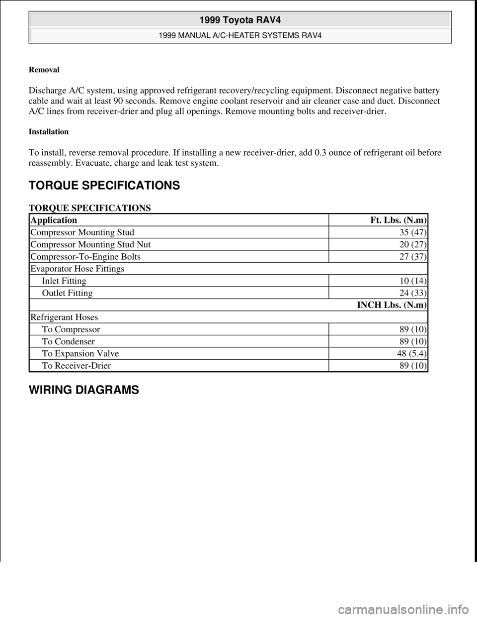
TORQUE SPECIFICATIONS
TORQUE SPECIFICATIONS
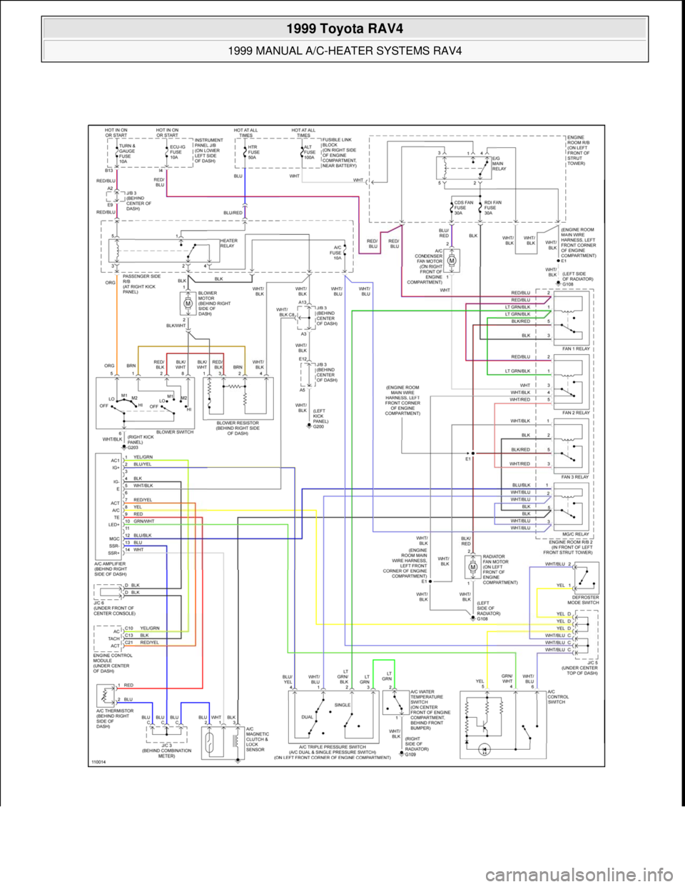
WIRING DIAGRAMS
ApplicationFt. Lbs. (N.m)
Compressor Mounting Stud35 (47)
Compressor Mounting Stud Nut20 (27)
Compressor-To-Engine Bolts27 (37)
Evaporator Hose Fittings
Inlet Fitting10 (14)
Outlet Fitting24 (33)
INCH Lbs. (N.m)
Refrigerant Hoses
To Compressor89 (10)
To Condenser89 (10)
To Expansion Valve48 (5.4)
To Receiver-Drier89 (10)
1999 Toyota RAV4
1999 MANUAL A/C-HEATER SYSTEMS RAV4
Microsoft
Sunday, November 22, 2009 10:29:28 AMPage 15 © 2005 Mitchell Repair Information Company, LLC.
Page 889 of 1632
1999 Toyota RAV4
1999 MANUAL A/C-HEATER SYSTEMS RAV4
Microsoft
Sunday, November 22, 2009 10:29:28 AMPage 16 © 2005 Mitchell Repair Information Company, LLC.
Page 890 of 1632

Fig. 10: Manual A/C-Heater System Wiring Diagram (RAV4)
1999 Toyota RAV4
1999 MANUAL A/C-HEATER SYSTEMS RAV4
Microsoft
Sunday, November 22, 2009 10:29:28 AMPage 17 © 2005 Mitchell Repair Information Company, LLC.