TOYOTA RAV4 1996 Service Repair Manual
Manufacturer: TOYOTA, Model Year: 1996, Model line: RAV4, Model: TOYOTA RAV4 1996Pages: 1632, PDF Size: 41.64 MB
Page 871 of 1632

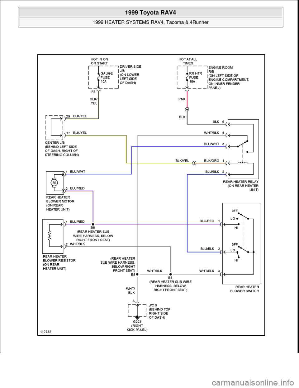
Fig. 13: Heater System Wiring Diagram (4Runner -Front)
1999 Toyota RAV4
1999 HEATER SYSTEMS RAV4, Tacoma & 4Runner
Microsoft
Sunday, November 22, 2009 10:30:50 AMPage 21 © 2005 Mitchell Repair Information Company, LLC.
Page 872 of 1632
1999 Toyota RAV4
1999 HEATER SYSTEMS RAV4, Tacoma & 4Runner
Microsoft
Sunday, November 22, 2009 10:30:50 AMPage 22 © 2005 Mitchell Repair Information Company, LLC.
Page 873 of 1632

Fig. 14: Heater System Wiring Diagram (4Runner -Rear)
1999 Toyota RAV4
1999 HEATER SYSTEMS RAV4, Tacoma & 4Runner
Microsoft
Sunday, November 22, 2009 10:30:50 AMPage 23 © 2005 Mitchell Repair Information Company, LLC.
Page 874 of 1632
1999 MANUAL A/C-HEATER SYSTEMS
RAV4
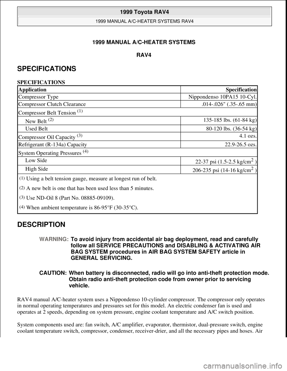
SPECIFICATIONS
SPECIFICATIONS
DESCRIPTION
RAV4 manual A/C-heater system uses a Nippondenso 10-cylinder compressor. The compressor only operates
in normal operating temperatures and pressures set for this model. An electric condenser fan is used and
operates at 2 speeds, depending on system pressure, engine coolant temperature and A/C switch position.
System components used are: fan switch, A/C amplifier, evaporator, thermistor, dual-pressure switch, engine
coolant temperature switch, compressor, condenser, receive
r-drier, and all the necessary pipes and hoses. Air
ApplicationSpecification
Compressor TypeNippondenso 10PA15 10-Cyl.
Compressor Clutch Clearance.014-.026" (.35-.65 mm)
Compressor Belt Tension (1)
New Belt (2) 135-185 lbs. (61-84 kg)
Used Belt80-120 lbs. (36-54 kg)
Compressor Oil Capacity (3) 4.1 ozs.
Refrigerant (R-134a) Capacity22.9-26.5 ozs.
System Operating Pressures (4)
Low Side22-37 psi (1.5-2.5 kg/cm2 )
High Side206-235 psi (14-16 kg/cm2 )
(1)Using a belt tension gauge, measure at longest run of belt.
(2)A new belt is one that has been used less than 5 minutes.
(3)Use ND-Oil 8 (Part No. 08885-09109).
(4)When ambient temperature is 86-95°F (30-35°C).
WARNING:To avoid injury from accidental air bag deployment, read and carefully
follow all SERVICE PRECAUTIONS and DISABLING & ACTIVATING AIR
BAG SYSTEM procedures in AIR BAG SYSTEM SAFETY article in
GENERAL SERVICING.
CAUTION: When battery is disconnected, radio will go into anti-theft protection mode.
Obtain radio anti-theft protection code from owner prior to servicing
vehicle.
1999 Toyota RAV4
1999 MANUAL A/C-HEATER SYSTEMS RAV4
1999 Toyota RAV4
1999 MANUAL A/C-HEATER SYSTEMS RAV4
Microsoft
Sunday, November 22, 2009 10:29:27 AMPage 1 © 2005 Mitchell Repair Information Company, LLC.
Microsoft
Sunday, November 22, 2009 10:29:33 AMPage 1 © 2005 Mitchell Repair Information Company, LLC.
Page 875 of 1632
door operation is controlled through cable connections. Compressor operation and associated A/C modes are
electrically controlled.
OPERATION
SYSTEM CONTROLS
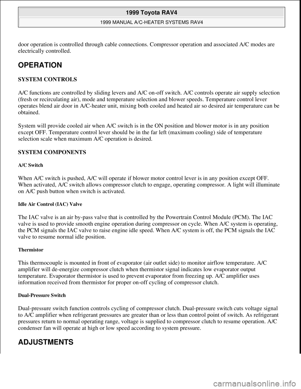
A/C functions are controlled by sliding levers and A/C on-off switch. A/C controls operate air supply selection
(fresh or recirculating air), mode and temperature selection and blower speeds. Temperature control lever
operates blend air door in A/C-heater unit, mixing both cooled and heated air so desired air temperature can be
obtained.
System will provide cooled air when A/C switch is in the ON position and blower motor is in any position
except OFF. Temperature control lever should be in the far left (maximum cooling) side of temperature
selection scale when maximum A/C operation is desired.
SYSTEM COMPONENTS
A/C Switch
When A/C switch is pushed, A/C will operate if blower motor control lever is in any position except OFF.
When activated, A/C switch allows compressor clutch to engage, operating compressor. A light will illuminate
on A/C push button when switch is activated.
Idle Air Control (IAC) Valve
The IAC valve is an air by-pass valve that is controlled by the Powertrain Control Module (PCM). The IAC
valve is used to provide smooth engine operation during compressor on cycle. When A/C system is operating,
the PCM signals the IAC valve to raise engine idle speed. When A/C system is off, the PCM signals the IAC
valve to resume normal idle position.
Thermistor
This thermocouple is mounted in front of evaporator (air outlet side) to monitor airflow temperature. A/C
amplifier will de-energize compressor clutch when thermistor signal indicates low evaporator output
temperature. Evaporator thermistor is used to prevent evaporator from freezing up. A/C amplifier uses
information received from thermistor for proper on-off cycling of compressor clutch.
Dual-Pressure Switch
Dual-pressure switch function controls cycling of compressor clutch. Dual-pressure switch cuts voltage signal
to A/C amplifier when refrigerant pressures are greater than or less than control point of switch. As refrigerant
pressures return to normal operating range, voltage is supplied to compressor clutch to resume operation. A/C
condenser fan will operate at high or low speed according to system pressure.
ADJUSTMENTS
1999 Toyota RAV4
1999 MANUAL A/C-HEATER SYSTEMS RAV4
Microsoft
Sunday, November 22, 2009 10:29:28 AMPage 2 © 2005 Mitchell Repair Information Company, LLC.
Page 876 of 1632
TROUBLE SHOOTING
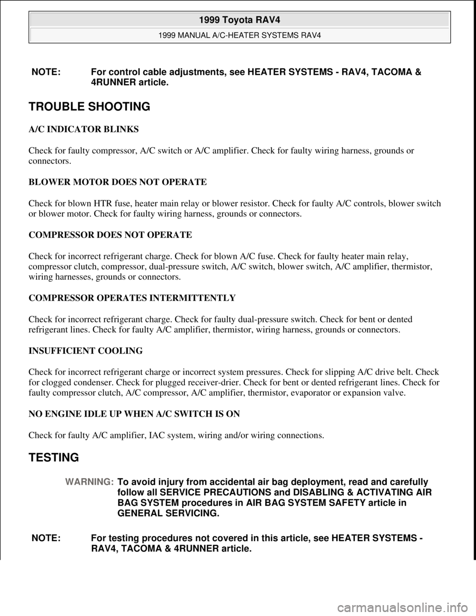
A/C INDICATOR BLINKS
Check for faulty compressor, A/C switch or A/C amplifier. Check for faulty wiring harness, grounds or
connectors.
BLOWER MOTOR DOES NOT OPERATE
Check for blown HTR fuse, heater main relay or blower resistor. Check for faulty A/C controls, blower switch
or blower motor. Check for faulty wiring harness, grounds or connectors.
COMPRESSOR DOES NOT OPERATE
Check for incorrect refrigerant charge. Check for blown A/C fuse. Check for faulty heater main relay,
compressor clutch, compressor, dual-pressure switch, A/C switch, blower switch, A/C amplifier, thermistor,
wiring harnesses, grounds or connectors.
COMPRESSOR OPERATES INTERMITTENTLY
Check for incorrect refrigerant charge. Check for faulty dual-pressure switch. Check for bent or dented
refrigerant lines. Check for faulty A/C amplifier, thermistor, wiring harness, grounds or connectors.
INSUFFICIENT COOLING
Check for incorrect refrigerant charge or incorrect system pressures. Check for slipping A/C drive belt. Check
for clogged condenser. Check for plugged receiver-drier. Check for bent or dented refrigerant lines. Check for
faulty compressor clutch, A/C compressor, A/C amplifier, thermistor, evaporator or expansion valve.
NO ENGINE IDLE UP WHEN A/C SWITCH IS ON
Check for faulty A/C amplifier, IAC system, wiring and/or wiring connections.
TESTING
NOTE: For control cable adjustments, see HEATER SYSTEMS - RAV4, TACOMA &
4RUNNER article.
WARNING:To avoid injury from accidental air bag deployment, read and carefully
follow all SERVICE PRECAUTIONS and DISABLING & ACTIVATING AIR
BAG SYSTEM procedures in AIR BAG SYSTEM SAFETY article in
GENERAL SERVICING.
NOTE: For testing procedures not covered in this article, see HEATER SYSTEMS -
RAV4, TACOMA & 4RUNNER article.
1999 Toyota RAV4
1999 MANUAL A/C-HEATER SYSTEMS RAV4
Microsoft
Sunday, November 22, 2009 10:29:28 AMPage 3 © 2005 Mitchell Repair Information Company, LLC.
Page 877 of 1632
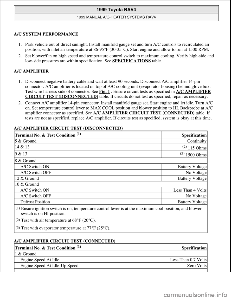
A/C SYSTEM PERFORMANCE
1. Park vehicle out of direct sunlight. Install manifold gauge set and turn A/C controls to recirculated air
position, with inlet air temperature at 86-95°F (30-35°C). Start engine and allow to run at 1500 RPM.
2. Set blower/fan on high speed and temperature control switch to maximum cooling. Verify high-side and
low-side pressures are within specification. See SPECIFICATIONS
table.
A/C AMPLIFIER
1. Disconnect negative battery cable and wait at least 90 seconds. Disconnect A/C amplifier 14-pin
connector. A/C amplifier is located on top of A/C cooling unit (evaporator housing) behind glove box.
Test wire harness side of connector. See Fig. 1
. Ensure circuit tests as specified in A/C AMPLIFIER
CIRCUIT TEST (DISCONNECTED) table. If circuits do not test as specified, repair as necessary.
2. Connect A/C amplifier 14-pin connector. Install manifold gauge set. Start engine and let idle. Turn A/C
on. Set temperature control lever to MAX COOL position and blower position to HI. Backprobe at A/C
amplifier connector as specified. See A/C AMPLIFIER CIRCUIT TEST (CONNECTED)
table. If
tests are not as specified, replace A/C amplifier. If circuits test as specified, system is okay at this time.
A/C AMPLIFIER CIRCUIT TEST (DISCONNECTED)
A/C AMPLIFIER CIRCUIT TEST (CONNECTED)
Terminal No. & Test Condition (1) Specification
5 & GroundContinuity
14 & 13(2) 115 Ohms
9 & 13(3) 1500 Ohms
8 & Ground
A/C Switch ONBattery Voltage
A/C Switch OFFNo Voltage
12 & GroundBattery Voltage
10 & Ground
A/C Switch ONLess Than 4 Volts
A/C Switch OFFNo Voltage
Defrost PositionBattery Voltage
(1)Ensure ignition switch is on, temperature control lever is at the maximum cool position, and blower
switch is on HI position.
(2)Test with air temperature at 68°F (20°C).
(3)Test with evaporator temperature at 77°F (25°C).
Terminal No. & Test Condition (1) Specification
1 & Ground
Engine Speed At IdleLess Than 0.7 Volts
Engine Speed At Idle-Up SpeedZero Volts
1999 Toyota RAV4
1999 MANUAL A/C-HEATER SYSTEMS RAV4
Microsoft
Sunday, November 22, 2009 10:29:28 AMPage 4 © 2005 Mitchell Repair Information Company, LLC.
Page 878 of 1632
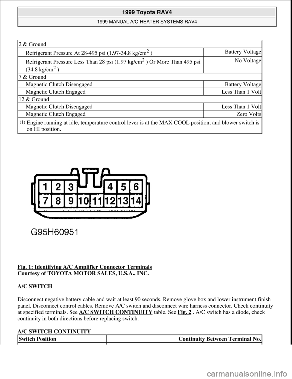
Fig. 1: Identifying A/C Amplifier Connector Terminals
Courtesy of TOYOTA MOTOR SALES, U.S.A., INC.
A/C SWITCH
Disconnect negative battery cable and wait at least 90 seconds. Remove glove box and lower instrument finish
panel. Disconnect control cables. Remove A/C switch and disconnect wire harness connector. Check continuity
at specified terminals. See A/C SWITCH CONTINUITY
table. See Fig. 2 . A/C switch has a diode, check
continuity in both directions before replacing switch.
A/C SWITCH CONTINUITY
2 & Ground
Refrigerant Pressure At 28-495 psi (1.97-34.8 kg/cm2 )Battery Voltage
Refrigerant Pressure Less Than 28 psi (1.97 kg/cm2 ) Or More Than 495 psi
(34.8 kg/cm
2 )
No Voltage
7 & Ground
Magnetic Clutch DisengagedBattery Voltage
Magnetic Clutch EngagedLess Than 1 Volt
12 & Ground
Magnetic Clutch DisengagedLess Than 1 Volt
Magnetic Clutch EngagedZero Volts
(1)Engine running at idle, temperature control lever is at the MAX COOL position, and blower switch is
on HI position.
Switch PositionContinuity Between Terminal No.
1999 Toyota RAV4
1999 MANUAL A/C-HEATER SYSTEMS RAV4
Microsoft
Sunday, November 22, 2009 10:29:28 AMPage 5 © 2005 Mitchell Repair Information Company, LLC.
Page 879 of 1632
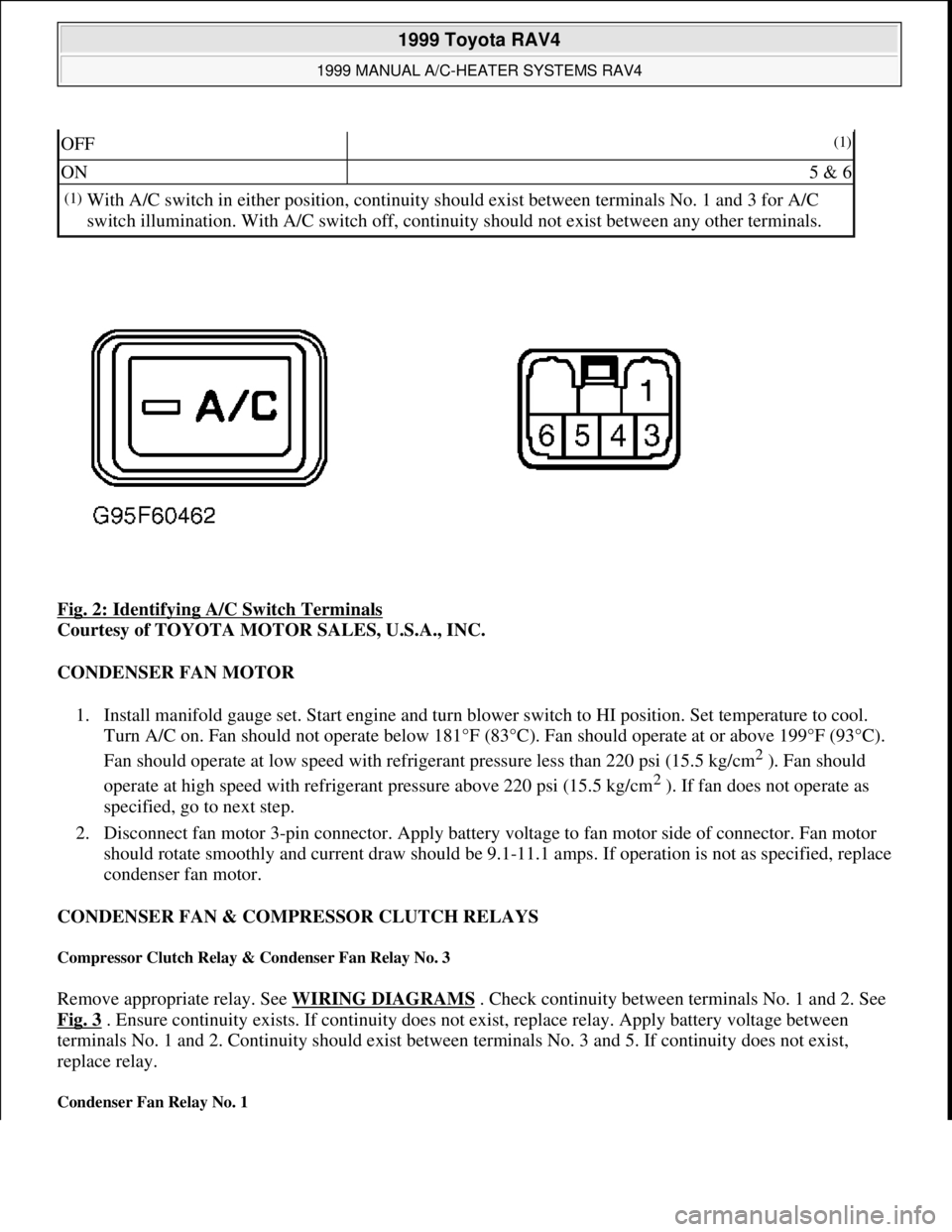
Fig. 2: Identifying A/C Switch Terminals
Courtesy of TOYOTA MOTOR SALES, U.S.A., INC.
CONDENSER FAN MOTOR
1. Install manifold gauge set. Start engine and turn blower switch to HI position. Set temperature to cool.
Turn A/C on. Fan should not operate below 181°F (83°C). Fan should operate at or above 199°F (93°C).
Fan should operate at low speed with refrigerant pressure less than 220 psi (15.5 kg/cm
2 ). Fan should
operate at high speed with refrigerant pressure above 220 psi (15.5 kg/cm
2 ). If fan does not operate as
specified, go to next step.
2. Disconnect fan motor 3-pin connector. Apply battery voltage to fan motor side of connector. Fan motor
should rotate smoothly and current draw should be 9.1-11.1 amps. If operation is not as specified, replace
condenser fan motor.
CONDENSER FAN & COMPRESSOR CLUTCH RELAYS
Compressor Clutch Relay & Condenser Fan Relay No. 3
Remove appropriate relay. See WIRING DIAGRAMS . Check continuity between terminals No. 1 and 2. See
Fig. 3
. Ensure continuity exists. If continuity does not exist, replace relay. Apply battery voltage between
terminals No. 1 and 2. Continuity should exist between terminals No. 3 and 5. If continuity does not exist,
replace relay.
Condenser Fan Relay No. 1
OFF(1)
ON5 & 6
(1)With A/C switch in either position, continuity should exist between terminals No. 1 and 3 for A/C
switch illumination. With A/C switch off, continuity should not exist between any other terminals.
1999 Toyota RAV4
1999 MANUAL A/C-HEATER SYSTEMS RAV4
Microsoft
Sunday, November 22, 2009 10:29:28 AMPage 6 © 2005 Mitchell Repair Information Company, LLC.
Page 880 of 1632
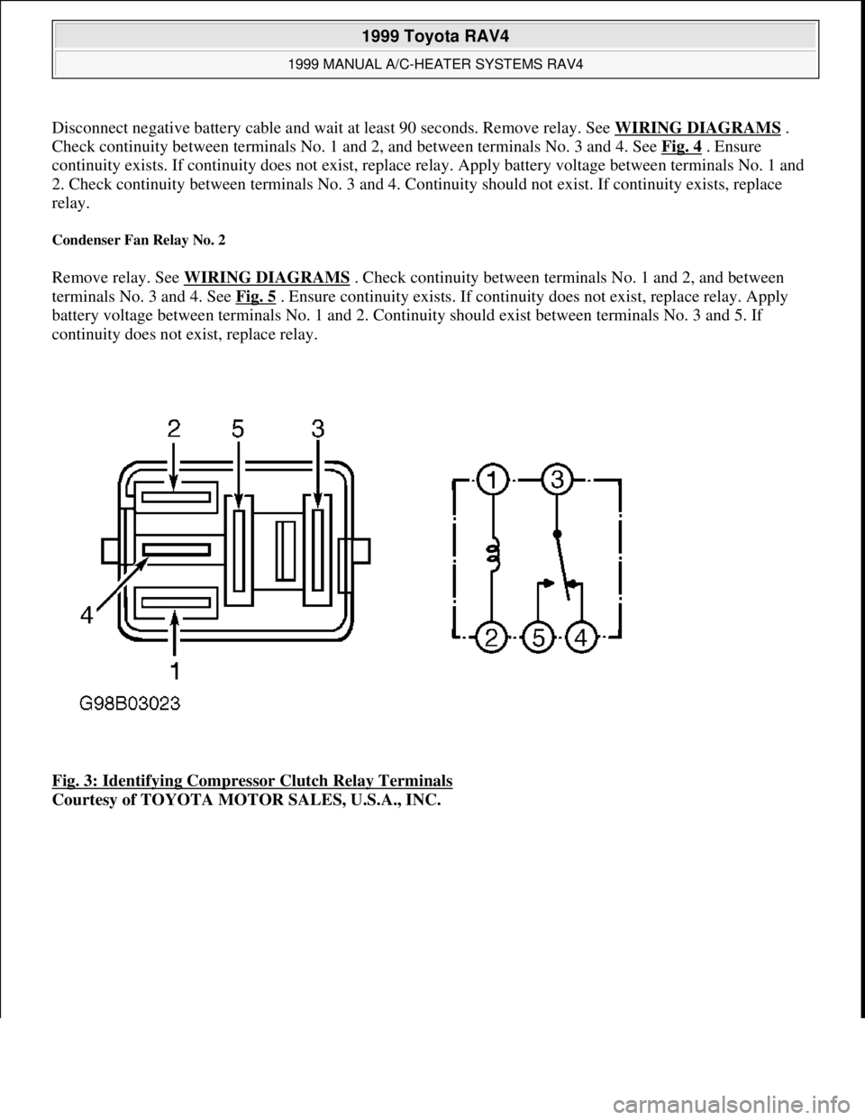
Disconnect negative battery cable and wait at least 90 seconds. Remove relay. See WIRING DIAGRAMS.
Check continuity between terminals No. 1 and 2, and between terminals No. 3 and 4. See Fig. 4
. Ensure
continuity exists. If continuity does not exist, replace relay. Apply battery voltage between terminals No. 1 and
2. Check continuity between terminals No. 3 and 4. Continuity should not exist. If continuity exists, replace
relay.
Condenser Fan Relay No. 2
Remove relay. See WIRING DIAGRAMS . Check continuity between terminals No. 1 and 2, and between
terminals No. 3 and 4. See Fig. 5
. Ensure continuity exists. If continuity does not exist, replace relay. Apply
battery voltage between terminals No. 1 and 2. Continuity should exist between terminals No. 3 and 5. If
continuity does not exist, replace relay.
Fig. 3: Identifying Compressor Clutch Relay Terminals
Courtesy of TOYOTA MOTOR SALES, U.S.A., INC.
1999 Toyota RAV4
1999 MANUAL A/C-HEATER SYSTEMS RAV4
Microsoft
Sunday, November 22, 2009 10:29:28 AMPage 7 © 2005 Mitchell Repair Information Company, LLC.