VOLVO V90 2017 Owners Manual
Manufacturer: VOLVO, Model Year: 2017, Model line: V90, Model: VOLVO V90 2017Pages: 594, PDF Size: 15.07 MB
Page 131 of 594

INSTRUMENTS AND CONTROLS
* Option/accessory.129
To lower the head restraint, the button (see illus- tration) must be depressed while the restraint iscarefully moved down.
WARNING
The centre seat head restraint must be in its lowest position when the centre seat is notused. When the centre seat is used, the headrestraint must be correctly adjusted to theheight of the passenger so that it covers thewhole of the back of the head if possible.
Electrical lowering of the rear seat's outer head restraints *
The outer head restraints can be lowered in two ways via the centre display:
Via the function view
Press the Headrest fold but-
ton to activate/deactivate low- ering.
Via settings
The car's electrical system must be in the ignition position II.
1. Press
Settings in the top view.
2. Press
My CarSeats. 3.
Select
Fold Headrest On Second Row
Seats to lower the rear outer head
restraints.
WARNING
Do not lower the outer head restraints if there are passengers in any of the outer seats.
Move the head restraint back manually until a click is heard.
WARNING
The head restraints must be in locked posi- tion after being raised.
Related information
• Rear seat (p. 128)
• Lowering the backrests in the rear seat (p. 130)
Page 132 of 594

INSTRUMENTS AND CONTROLS
* Option/accessory.
130
Lowering the backrests in the rear seat
The rear seat's backrest is divided into two parts. The two parts can be lowered forwardindividually.
WARNING
Adjust the seat and fix it before driving away. Take care when adjusting the seat. Uncontrol-led or careless adjustment can lead to trap-ping injuries.
IMPORTANT
There must be no objects on the rear seat when the backrest is to be folded down. Theseat belts must not be connected either. Oth-erwise there is a risk of damaging the rearseat upholstery.
IMPORTANT
The integrated booster cushions * on the
outer seats must be lowered before lowering the seat. The armrest * for the centre seat must be
raised before lowering the seat. If the car has private locking, the tailgate must be closed before lowering the seat.
NOTE
The front seats may need to be pushed for- wards, and/or the backrests adjustedupwards, in order that the rear backrests canbe fully folded forward.
Lowering the backrest
Car with electronic folding
If the car is equipped with electronic folding of the rear seat * there are buttons located in the
cargo area. The backrests can also be lowered manually.
WARNING
Pay attention that people are not at risk of being trapped during the automatic folding ofthe rear seat. Since this takes place automati-cally on the press of a button, no one must beon or too close to the rear seat.
For electronically controlled folding of backrests:
1. Ensure that there are no occupants or objects in the rear seat.
2. Lower the centre seat's head restraint man- ually.
3. Hold the button for folding depressed. The buttons are marked L and R for left and right backrest section respectively.
4. The backrests are lowered automatically to horizontal position. The head restraints arealso lowered automatically.
To facilitate folding of the rear seat, the car mustbe stationary and the tailgate open. To lower the backrest manually:
Page 133 of 594
INSTRUMENTS AND CONTROLS
}}
* Option/accessory.131
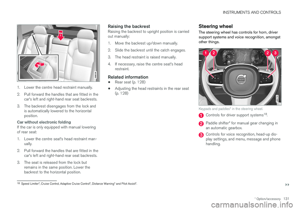
1. Lower the centre head restraint manually.
2. Pull forward the handles that are fitted in the
car's left and right-hand rear seat backrests.
3. The backrest disengages from the lock and is automatically lowered to the horizontal position.
Car without electronic folding
If the car is only equipped with manual lowering of rear seat:
1. Lower the centre seat's head restraint man-ually.
2. Pull forward the handles that are fitted in the car's left and right-hand rear seat backrests.
3. The seat is released from the lock but remains in the same position. Lower the backrest to the horizontal position.
Raising the backrestRaising the backrest to upright position is carriedout manually:
1. Move the backrest up/down manually.
2. Slide the backrest until the catch engages.
3. The head restraint is raised manually.
4. If necessary, raise the centre seat's headrestraint.
Related information
• Rear seat (p. 128)
• Adjusting the head restraints in the rear seat (p. 128)
Steering wheel The steering wheel has controls for horn, driver support systems and voice recognition, amongstother things.
Keypads and paddles
* in the steering wheel.
Controls for driver support systems 18
.
Paddle shifter * for manual gear changing in
an automatic gearbox.
Controls for voice recognition, head-up dis- play settings, and menu, message and phonehandling.
18 Speed Limiter *, Cruise Control, Adaptive Cruise Control *, Distance Warning * and Pilot Assist *.
Page 134 of 594
||
INSTRUMENTS AND CONTROLS
* Option/accessory.
132
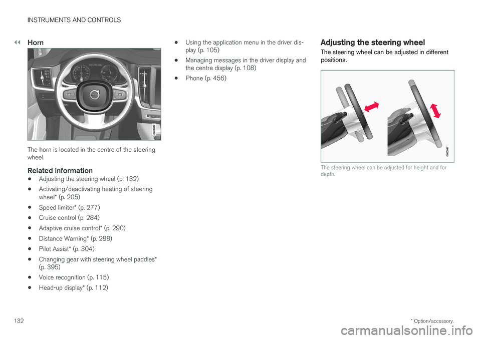
Horn
The horn is located in the centre of the steering wheel.
Related information
• Adjusting the steering wheel (p. 132)
• Activating/deactivating heating of steering wheel
* (p. 205)
• Speed limiter
* (p. 277)
• Cruise control (p. 284)
• Adaptive cruise control
* (p. 290)
• Distance Warning
* (p. 288)
• Pilot Assist
* (p. 304)
• Changing gear with steering wheel paddles
*
(p. 395)
• Voice recognition (p. 115)
• Head-up display
* (p. 112) •
Using the application menu in the driver dis- play (p. 105)
• Managing messages in the driver display andthe centre display (p. 108)
• Phone (p. 456)
Adjusting the steering wheel
The steering wheel can be adjusted in different positions.
The steering wheel can be adjusted for height and for depth.
Page 135 of 594
INSTRUMENTS AND CONTROLS
133
Steering wheel adjustment can be made in differ- ent ways depending on whether or not the car is equipped with knee airbag
19
.
WARNING
Adjust the steering wheel and fix it before driving away.
With speed related power steering the level of steering force can be adjusted. Steering force isregulated according to the car's speed in order togive the driver enhanced road responsiveness.
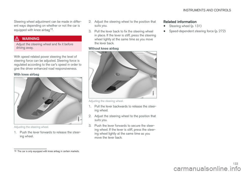
With knee airbag
Adjusting the steering wheel.
1. Push the lever forwards to release the steer- ing wheel. 2. Adjust the steering wheel to the position that
suits you.
3. Pull the lever back to fix the steering wheel in place. If the lever is stiff, press the steering wheel lightly at the same time as you movethe lever back.
Without knee airbag
Adjusting the steering wheel.
1. Pull the lever backwards to release the steer-ing wheel.
2. Adjust the steering wheel to the position that suits you.
3. Push the lever forwards to secure the steer- ing wheel. If the lever is stiff, press the steer- ing wheel lightly at the same time as youmove the lever back.
Related information
• Steering wheel (p. 131)
• Speed-dependent steering force (p. 272)
19
The car is only equipped with knee airbag in certain markets.
Page 136 of 594
INSTRUMENTS AND CONTROLS
* Option/accessory.
134
Headlamp control
Use the light controls in the left-hand stalk switch to activate external lighting. Use thethumbwheels in the instrument panel to adjust headlamp levelling 20
and the brightness of the
interior lighting.
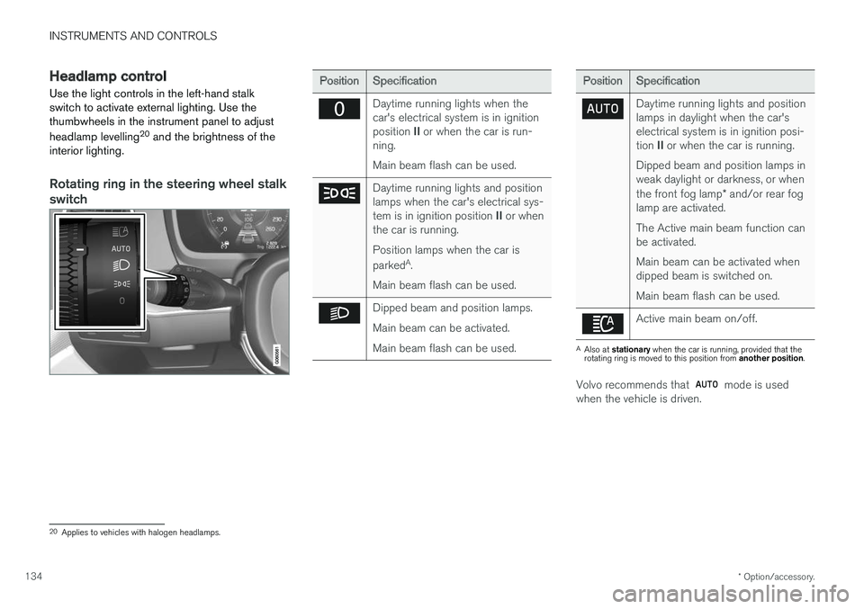
Rotating ring in the steering wheel stalk
switch
Position Specification
Daytime running lights when the car's electrical system is in ignition position II or when the car is run-
ning. Main beam flash can be used.
Daytime running lights and position lamps when the car's electrical sys- tem is in ignition position II or when
the car is running. Position lamps when the car is parked A
.
Main beam flash can be used.
Dipped beam and position lamps. Main beam can be activated.Main beam flash can be used.
Position Specification
Daytime running lights and position lamps in daylight when the car'selectrical system is in ignition posi- tion II or when the car is running.
Dipped beam and position lamps in weak daylight or darkness, or when the front fog lamp * and/or rear fog
lamp are activated. The Active main beam function can be activated. Main beam can be activated when dipped beam is switched on. Main beam flash can be used.
Active main beam on/off.
A Also at stationary when the car is running, provided that the
rotating ring is moved to this position from another position.
Volvo recommends that mode is used
when the vehicle is driven.
20 Applies to vehicles with halogen headlamps.
Page 137 of 594
INSTRUMENTS AND CONTROLS
}}
* Option/accessory.135
WARNING
The car's audio system is not able to deter- mine when daylight is too weak or sufficientlystrong, e.g. in fog and rain, in all situations. The driver is always responsible for ensuring that the car is driven with a beam pattern suit-able for the traffic situation and in accordancewith applicable traffic regulations.
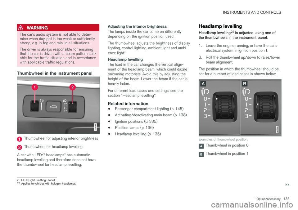
Thumbwheel in the instrument panel
Thumbwheel for adjusting interior brightness
Thumbwheel for headlamp levelling
A car with LED 21
headlamps * has automatic
headlamp levelling and therefore does not have the thumbwheel for headlamp levelling.
Adjusting the interior brightness
The lamps inside the car come on differently depending on the ignition position used. The thumbwheel adjusts the brightness of display lighting, control lighting, ambient light and ambi- ence light *.
Headlamp levelling
The load in the car changes the vertical align- ment of the headlamp beam, which could dazzleoncoming motorists. Avoid this by adjusting theheight of the beam. Lower the beam if the car isheavily laden. For different load cases and settings, see the section "Headlamp levelling".
Related information
• Passenger compartment lighting (p. 145)
• Activating/deactivating main beam (p. 138)
• Ignition positions (p. 385)
• Position lamps (p. 136)
• Headlamp levelling (p. 135)
Headlamp levelling
Headlamp levelling 22
is adjusted using one of
the thumbwheels in the instrument panel.
1. Leave the engine running, or have the car's
electrical system in ignition position I.
2. Roll the thumbwheel up/down to raise/lower beam alignment.
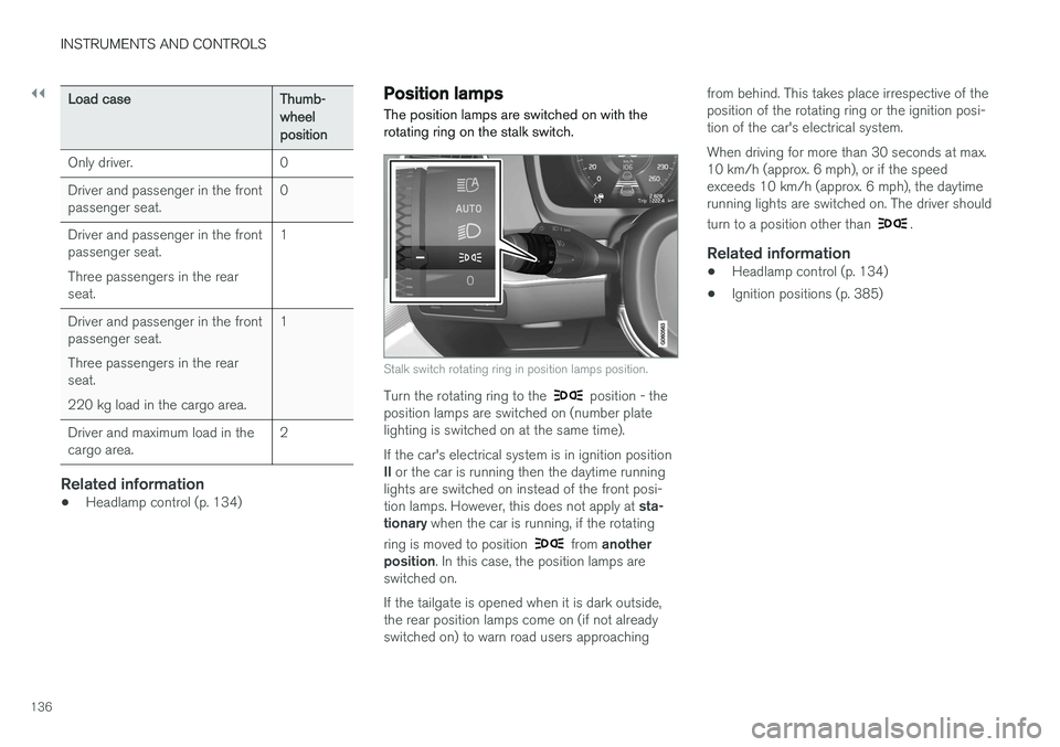
The position in which the thumbwheel should be set for a number of load cases is shown below.
Examples of thumbwheel position.
Thumbwheel in position 0
Thumbwheel in position 1
21 LED (Light Emitting Diode)
22 Applies to vehicles with halogen headlamps.
Page 138 of 594
||
INSTRUMENTS AND CONTROLS
136
Load caseThumb- wheelposition
Only driver. 0 Driver and passenger in the front passenger seat. 0
Driver and passenger in the frontpassenger seat. Three passengers in the rear seat. 1
Driver and passenger in the frontpassenger seat. Three passengers in the rear seat. 220 kg load in the cargo area. 1
Driver and maximum load in the cargo area. 2
Related information
•
Headlamp control (p. 134)
Position lamps
The position lamps are switched on with the rotating ring on the stalk switch.
Stalk switch rotating ring in position lamps position.
Turn the rotating ring to the position - the
position lamps are switched on (number plate lighting is switched on at the same time). If the car's electrical system is in ignition position II or the car is running then the daytime running
lights are switched on instead of the front posi-tion lamps. However, this does not apply at sta-
tionary when the car is running, if the rotating
ring is moved to position
from another
position . In this case, the position lamps are
switched on. If the tailgate is opened when it is dark outside, the rear position lamps come on (if not alreadyswitched on) to warn road users approaching from behind. This takes place irrespective of theposition of the rotating ring or the ignition posi-tion of the car's electrical system. When driving for more than 30 seconds at max. 10 km/h (approx. 6 mph), or if the speedexceeds 10 km/h (approx. 6 mph), the daytimerunning lights are switched on. The driver should turn to a position other than
.
Related information
•
Headlamp control (p. 134)
• Ignition positions (p. 385)
Page 139 of 594
INSTRUMENTS AND CONTROLS
}}
* Option/accessory.137
Daytime running lights The daytime running lights are switched on when the rotating ring on the stalk switch is in position
, or as well as when
the car's electrical system is in ignition position II
or when the car is running. For the
posi-
tion, this only applies in daylight. In weak daylight or darkness, dipped beam is switched oninstead.
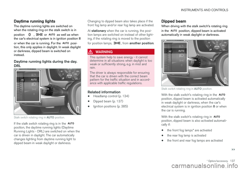
Daytime running lights during the day.
DRL
Stalk switch rotating ring in AUTO position.
If the stalk switch rotating ring is in the position, the daytime running lights (Daytime Running Lights - DRL) are switched on when thecar is driven in daylight. The car automaticallychanges lighting from daytime running light todipped beam in weak daylight or darkness. Changing to dipped beam also takes place if thefront fog lamp and/or rear fog lamp are activated. At
stationary when the car is running, the posi-
tion lamps are switched on instead of other light- ing, if the rotating ring is moved to the position for position lamps,
, from another position .
WARNING
This system help to save energy - it cannot determine in all situations when daylight is tooweak or sufficiently strong, e.g. in mist andrain. The driver is always responsible for ensuring that the car is driven with the correct beampattern for the traffic situation and in accord-ance with applicable traffic regulations.
Related information
•Headlamp control (p. 134)
• Dipped beam (p. 137)
• Ignition positions (p. 385)
Dipped beam
When driving with the stalk switch's rotating ring in the
position, dipped beam is activated
automatically in weak daylight or darkness.
Stalk switch rotating ring in AUTO position.
With the stalk switch's rotating ring in the position, dipped beam is activated automatically in weak daylight or darkness, when the car's electrical system is in ignition position II or when
the car is running. With the stalk switch's rotating ring in
position, dipped beam is also activated automati- cally if:
• the front fog lamps
* are activated
• the rear fog lamp is activated
• the front and rear fog lamps are activated
Page 140 of 594

||
INSTRUMENTS AND CONTROLS
138Dipped beam is always switched on when the rotating ring on the stalk switch is in position
when the car's electrical system is in igni-
tion position II or when the car is running.
Tunnel detection
The car detects when it is driven into a tunnel and switches from daytime running lights todipped beam. Note that the rotating ring in the left-hand stalk switch must be in
mode for tunnel detec-
tion to work.
Related information
• Daytime running lights (p. 137)
• Headlamp control (p. 134)
• Ignition positions (p. 385)
Activating/deactivating main beam Main beam is activated with the stalk switch. Active main beam is activated with the rotating ring on the stalk switch.
Steering wheel stalk switch with rotating ring.
Position for main beam flash
Position for main beam
Main beam flashMove the stalk switch backwards slightly to main beam flash position. Main beam comes on untilthe stalk switch is released.
Main beamMain beam can be activated when the steeringwheel stalk switch's rotating ring is in position
23
or . Activate main beam by moving
the stalk switch forwards. Deactivate by moving the stalk switch backwards. When main beam has been activated the
symbol illuminates in the driver display.
Active main beamActive main beam is a function which uses a camera sensor at the top edge of the windscreento detect the headlamp beams from oncomingtraffic or the rear lights of vehicles in front, andthen switches from main beam to dipped beam.The function can also take streetlights intoaccount. Main beam is reactivated when the camera sen- sor no longer sees any oncoming vehicles orvehicles ahead.
Car with halogen headlamps
The lighting returns to main beam about a sec- ond after the camera sensor no longer detectsthe headlamp beams from oncoming traffic or therear lights from vehicles in front.
23 When dipped beam is activated.