ACURA NSX 1991 Service Repair Manual
Manufacturer: ACURA, Model Year: 1991, Model line: NSX, Model: ACURA NSX 1991Pages: 1640, PDF Size: 60.48 MB
Page 1081 of 1640
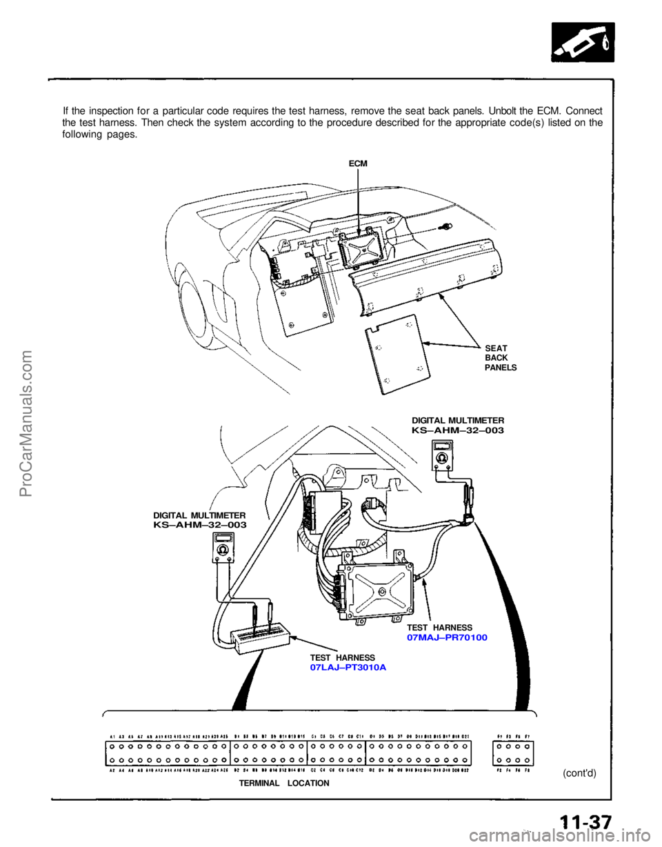
If the inspection for a particular code requires the test harness, remove the seat back panels. Unbolt the ECM. Connect
the test harness. Then check the system according to the procedure described for the appropriate code(s) listed on the
following pages.
ECM
SEAT
BACK
PANELS
DIGITAL MULTIMETER
KS–AHM–32–003
TEST HARNESS
07MAJ–PR 70100
TEST HARNESS
07LAJ–PT3010A
TERMINAL LOCATION (cont'd)
DIGITAL MULTIMETER
KS–AHM–32–003ProCarManuals.com
Page 1082 of 1640
Troubleshooting
Self-diagnostic Procedures (cont'd)
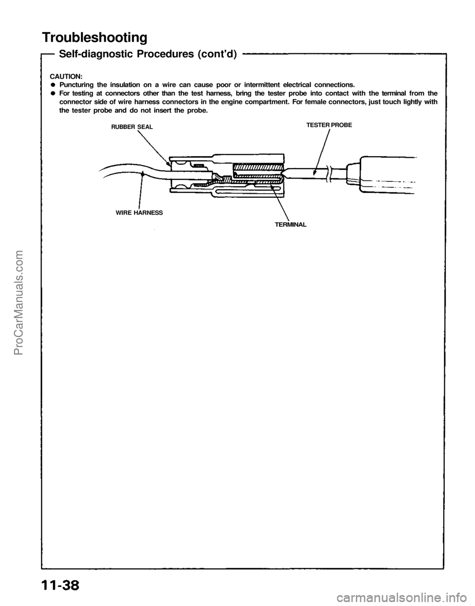
CAUTION:
Puncturing the insulation on a wire can cause poor or intermittent electrical connections.
For testing at connectors other than the test harness, bring the tester probe into contact with the terminal from the
connector side of wire harness connectors in the engine compartment. For female connectors, just touch lightly with
the tester probe and do not insert the probe.
TESTER PROBE
TERMINAL
WIRE HARNESS
RUBBER SEALProCarManuals.com
Page 1083 of 1640
How to Read Flowcharts
A flowchart is designed to be used from start to final repair. It's like a map showing you the shortest distance. But
beware: if you go off the "map" anywhere but a "stop" symbol, you can easily get lost.
(bold type)
(bold type)
Describes the conditions or situation to start a troubleshooting flowchart.
Asks you to do something; perform a test, set up a condition etc.
Asks you about the result of an action, then sends you in the appropriate troubleshooting direction.
The end of a series of actions and decisions, describes a final repair action and sometimes directs you
to an earlier part of the flowchart to confirm your repair.
NOTE:
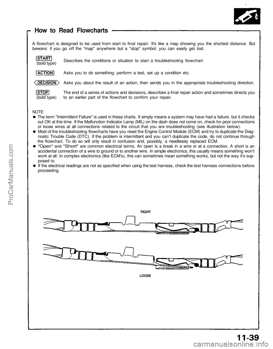
The term "Intermittent Failure" is used in these charts. It simply means a system may have had a failure, but it checks
out OK at this time. If the Malfunction Indicator Lamp (MIL) on the dash does not come on, check for poor connections
or loose wires at all connections related to the circuit that you are troubleshooting (see illustration below).
Most of the troubleshooting flowcharts have you reset the Engine Control Module (ECM) and try to duplicate the Diag-
nostic Trouble Code (DTC). If the problem is intermittent and you can't duplicate the code, do not continue through
the flowchart. To do so will only result in confusion and, possibly, a needlessly replaced ECM.
"Open"
and
"Short"
are
common electrical terms.
An
open
is a
break
in a
wire
or at a
connection.
A
short
is an
accidental connection of a wire to ground or to another wire. In simple electronics, this usually means something won't
work at all. In complex electronics (like ECM's), this can sometimes mean something works, but not the way it's sup-
posed to.
If the electrical readings are not as specified when using the test harness, check the test harness connections before
proceeding.
TIGHT
LOOSEProCarManuals.com
Page 1084 of 1640
PGM-FI System
System Description
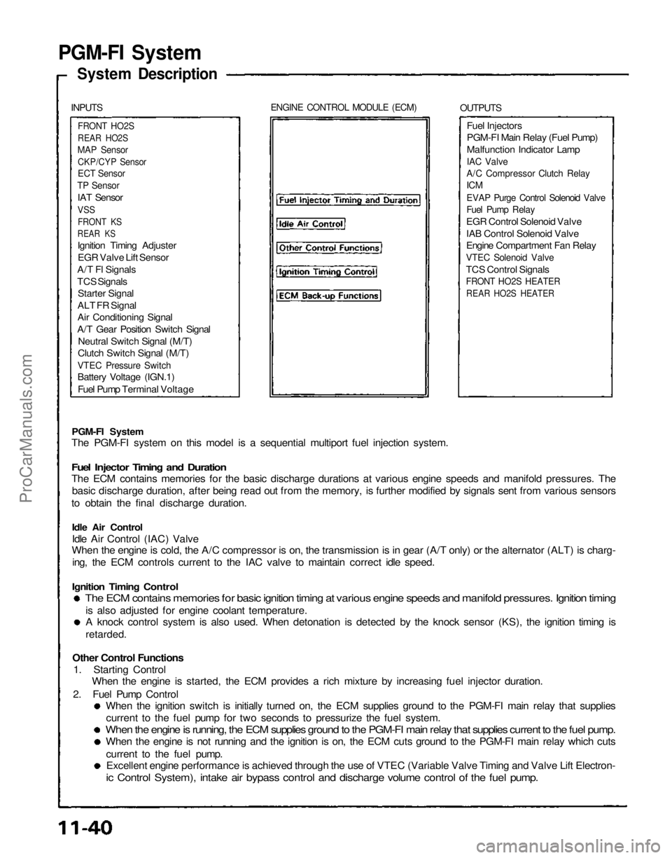
INPUTS
ENGINE CONTROL MODULE (ECM)
OUTPUTS
FRONT HO2S
REAR HO2S
MAP Sensor
CKP/CYP Sensor
ECT Sensor
TP Sensor
IAT Sensor
VSS
FRONT KS
REAR KS
Ignition Timing Adjuster
EGR Valve Lift Sensor
A/T Fl Signals
TCS Signals
Starter Signal
ALT FR Signal
Air Conditioning Signal
A/T Gear Position Switch Signal
Neutral Switch Signal (M/T)
Clutch Switch Signal (M/T)
VTEC Pressure Switch
Battery Voltage (IGN.1)
Fuel Pump Terminal Voltage
Fuel Injectors
PGM-FI Main Relay (Fuel Pump)
Malfunction Indicator Lamp
IAC Valve
A/C Compressor Clutch Relay
ICM
EVAP Purge Control Solenoid Valve
Fuel Pump Relay
EGR Control Solenoid Valve
IAB Control Solenoid Valve
Engine Compartment Fan Relay
VTEC Solenoid Valve
TCS Control Signals
FRONT HO2S HEATER
REAR HO2S HEATER
PGM-FI System
The PGM-FI system on this model is a sequential multiport fuel injection system.
Fuel Injector Timing and Duration
The ECM contains memories for the basic discharge durations at various engine speeds and manifold pressures. The
basic discharge duration, after being read out from the memory, is further modified by signals sent from various sensors
to obtain the final discharge duration.
Idle Air Control
Idle Air Control (IAC) Valve
When the engine is cold, the A/C compressor is on, the transmission is in gear (A/T only) or the alternator (ALT) is charg-
ing, the ECM controls current to the IAC valve to maintain correct idle speed.
Ignition Timing Control
The ECM contains memories for basic ignition timing at various engine speeds and manifold pressures. Ignition timing
is also adjusted for engine coolant temperature.
A knock control system is also used. When detonation is detected by the knock sensor (KS), the ignition timing is
retarded.
Other Control Functions
1. Starting Control
When the engine is started, the ECM provides a rich mixture by increasing fuel injector duration.
2. Fuel Pump Control
When the ignition switch is initially turned on, the ECM supplies ground to the PGM-FI main relay that supplies
current to the fuel pump for two seconds to pressurize the fuel system.
When the engine is running, the ECM supplies ground to the PGM-FI main relay that supplies current to the fuel pump.
When the engine is not running and the ignition is on, the ECM cuts ground to the PGM-FI main relay which cuts
current to the fuel pump.
Excellent engine performance is achieved through the use of VTEC (Variable Valve Timing and Valve Lift Electron-
ic Control System), intake air bypass control and discharge volume control of the fuel pump.ProCarManuals.com
Page 1085 of 1640
3. Fuel Cut-off Control
During deceleration with the throttle valve closed, current to the fuel injectors is cut off to improve fuel economy
at speeds over 1,500 rpm.
Fuel cut-off action also takes place when engine speed exceeds, 8,300 rpm, regardless of the position of the
throttle valve, to protect the engine from over-revving.
4. A/C Compressor Clutch Relay
When the ECM receives a demand for cooling from the air conditioning system, it delays the compressor from being
energized, and enriches the mixture to assure smooth translation to the A/C mode.
5. Evaporative Emission (EVAP) Purge Control Solenoid Valve
When the engine coolant temperature is below 1 58 °F (70°C) the ECM supplies a ground to the EVAP purge control
solenoid valve which cuts vacuum to the EVAP purge control diaphragm valve.
6. Intake Air Bypass (IAB) Control Solenoid Valve
When the engine speed is below 4,800 rpm, the IAB control solenoid valve is activated by a signal from the ECM.
Intake air then flows through the smaller chamber, and hight torque is delivered. To increase air flow at engine speeds
higher than 4,800 rpm, the solenoid valve is deactivated by the ECM, and the intake air flows through the larger
chamber.
7. Exhaust Gas Recirculation (EGR) Control Solenoid Valve
When the EGR is required for control of oxides of nitrogen (NOx) emissions, the ECM supplies ground to the EGR
control solenoid valve which supplies regulated vacuum to the EGR valve.
ECM fail-safe/back-up Functions
1. Fail-Safe Function
When an abnormality occurs in a signal from a sensor, the ECM ignores that signal and assumes a pre-programmed
valve for that sensor that allows the engine to continue to run.
2. Back-up Function
When an abnormality occurs in the ECM itself, the fuel injectors are controlled by a back-up circuit independent of
the system in order to permit minimal driving.
3. Self-diagnosis Function [Malfunction Indicator Lamp (MIL)]
When an abnormality occurs in a signal from a sensor, the ECM lights the MIL and stores the diagnostic trouble code
in erasable memory. When the ignition is initially turned in, the ECM supplies ground for the MIL for two seconds
to check the MIL bulb condition.ProCarManuals.com
Page 1086 of 1640
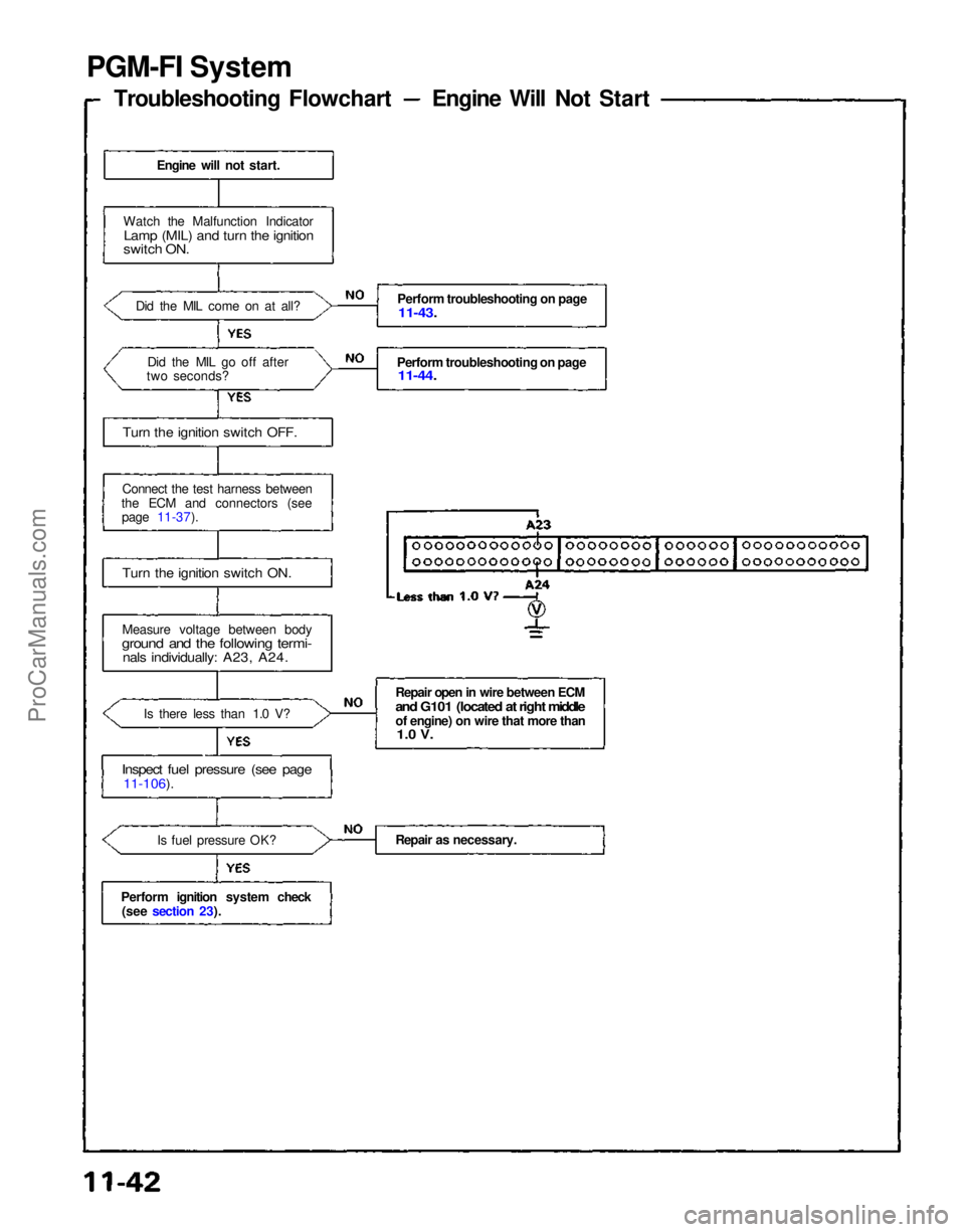
PGM-FI System
Troubleshooting Flowchart Engine Will Not Start
Engine will not start.
Watch the Malfunction Indicator
Lamp (MIL) and turn the ignition
switch ON.
Did the MIL come on at all?Did the MIL go off after
two seconds?
Turn the ignition switch OFF.
Connect the test harness between
the ECM and connectors (see page 11-37).
Turn the ignition switch ON.
Measure voltage between body
ground and the following termi-
nals individually: A23, A24.
Is there less than 1.0 V?
Inspect fuel pressure (see page
11-106).
Is fuel pressure OK?
Perform ignition system check (see section 23
).
Perform troubleshooting on page
11-43.
Perform troubleshooting on page
11-44.
Repair open in wire between ECM
and G101 (located at right middle
of engine) on wire that more than
1.0 V.
Repair as necessary.ProCarManuals.com
Page 1087 of 1640
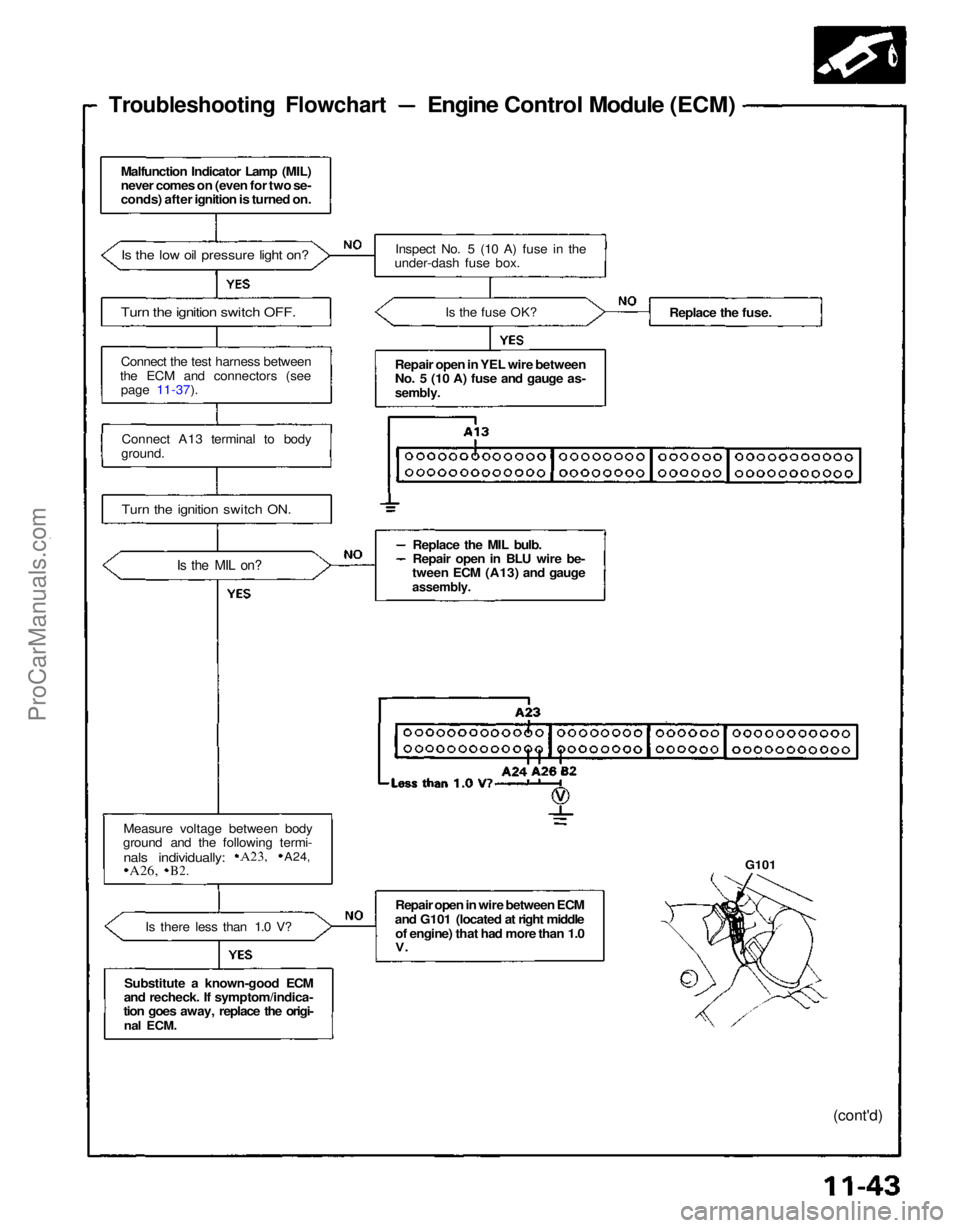
Troubleshooting Flowchart
Engine Control Module (ECM)
Malfunction Indicator Lamp (MIL)
never comes on (even for two se-
conds) after ignition is turned on.
Is the low oil pressure light on?
Turn the ignition switch OFF.
Connect the test harness between
the ECM and connectors (see page 11-37).
Connect A13 terminal to body
ground.
Turn the ignition switch ON.
Is the MIL on?
Measure voltage between body
ground and the following termi-
Is there less than 1.0 V?
Substitute a known-good ECM
and recheck. If symptom/indica-
tion goes away, replace the origi-
nal
ECM. Inspect No. 5 (10 A) fuse in the
under-dash fuse box.
Is the fuse OK?
Repair open in YEL wire between
No. 5 (10 A) fuse and gauge as-
sembly.
Replace the MIL bulb.
Repair open in BLU wire be-
tween ECM (A13) and gauge
assembly.
Repair open in wire between ECM
and G101 (located at right middle of engine) that had more than 1.0
V.
Replace the fuse.
G101
(cont'd)
nals individually:
A23,
A24,
A26,
B2.ProCarManuals.com
Page 1088 of 1640
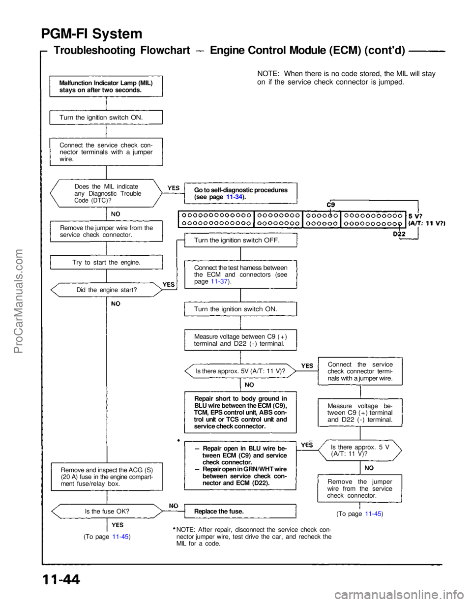
PGM-FI System
Troubleshooting Flowchart
Engine Control Module (ECM) (cont'd)
Malfunction Indicator Lamp (MIL) stays on after two seconds.
Turn the ignition switch ON.
Connect the service check con-
nector terminals with a jumper
wire.
Does the MIL indicate
any Diagnostic Trouble
Code (DTC)?
Remove the jumper wire from the
service check connector.
Try to start the engine.Did the engine start?
Remove and inspect the ACG (S) (20 A) fuse in the engine compart-
ment fuse/relay box.
Is the fuse OK?
(To page 11-45) Go to self-diagnostic procedures
(see page 11-34).
Turn the ignition switch OFF.
Connect the test harness between
the ECM and connectors (see page 11-37).
Turn the ignition switch ON.
Measure voltage between C9 (+)
terminal and D22 (-) terminal.
Is there approx. 5V (A/T: 11 V)?
Repair short to body ground in
BLU wire between the ECM (C9),
TCM, EPS control unit, ABS con-
trol unit or TCS control unit and service check connector.
Repair open in BLU wire be-
tween ECM (C9) and service check connector.
Repair open in GRN/WHT wire
between service check con-
nector and ECM (D22).
Replace the fuse.
NOTE: After repair, disconnect the service check con-
nector jumper wire, test drive the car, and recheck the
MIL for a code. NOTE: When there is no code stored, the MIL will stay
on if the service check connector is jumped.
Connect the service
check connector termi-
nals with a jumper wire.
Measure voltage be-
tween C9 (+) terminal
and D22 (-) terminal.
Is there approx. 5 V(A/T:
11 V)?
Remove the jumper
wire from the service
check connector.
(To page 11-45)ProCarManuals.com
Page 1089 of 1640
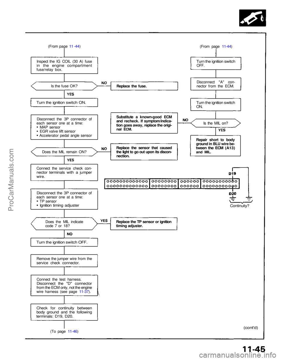
(From page 11 -44)
Inspect the IG COIL (30 A) fuse
in the engine compartment
fuse/relay box.
Is the fuse OK?
Turn the ignition switch ON.
Disconnect the 3P connector of
each sensor one at a time: MAP sensor
EGR
valve
lift
sensor
Accelerator pedal angle sensor
Does the MIL remain ON?
Connect the service check con-
nector terminals with a jumper
wire.
Disconnect the 3P connector of
each sensor one at a time:
TP sensor
Ignition timing adjuster
Does the MIL indicate
code 7 or 18?
Turn the ignition switch OFF.
Remove the jumper wire from the
service check connector.
Connect the test harness.
Disconnect the "D" connector
from the ECM only, not the engine
wire harness (see page 11-37).
Check for continuity between
body ground and the following
terminals: D19, D20.
(To page 11-46) Replace the fuse.
Substitute a known-good ECM
and recheck. If symptom/indica-
tion goes away, replace the origi-
nal
ECM.
Replace the sensor that caused
the light to go out upon its discon- nection.
Replace the TP sensor or ignition
timing adjuster. (From page 11-44)
Turn the ignition switch
OFF.
Disconnect "A" con-
nector from the ECM.
Turn the ignition switch
ON.
Is the MIL on?
Repair short to body
ground in BLU wire be-
tween the ECM (A13)
and
MIL.
Continuity?
(cont'd)ProCarManuals.com
Page 1090 of 1640
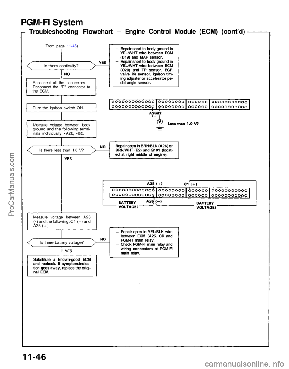
PGM-FI System
Troubleshooting Flowchart Engine Control Module (ECM) (cont'd)
(From page 11-45)
Is there continuity?
Reconnect all the connectors. Reconnect the "D" connector to
the
ECM.
Turn the ignition switch ON.
Measure voltage between body
ground and the following termi-
nals individually:
A26,
B2.
Is there less than 1.0 V?
Measure voltage between A26
(-) and the following: C1 (+) and
A25 ( + ).
Is there battery voltage?
Substitute a known-good ECM
and recheck. If symptom/indica-
tion goes away, replace the origi-
nal
ECM. Repair short to body ground in
YEL/WHT wire between ECM
(D19) and MAP sensor.
Repair short to body ground in
YEL/WHT wire between ECM
(O20) and TP sensor. EGR
valve life sensor, ignition tim-
ing adjuster or accelerator pe-
dal angle sensor.
Repair open in BRN/BLK (A26) or
BRN/WHT (B2) and G101 (locat-
ed at right middle of engine).
Repair open in YEL/BLK wire
between ECM (A25. CD and
PGM-FI main relay.
Check PGM-FI main relay and
wiring connectors at PGM-FI
main relay.ProCarManuals.com