ACURA TL 1995 Service Repair Manual
Manufacturer: ACURA, Model Year: 1995, Model line: TL, Model: ACURA TL 1995Pages: 1771, PDF Size: 62.49 MB
Page 1521 of 1771
Recovery
Use only service equipment that is U.L.-listed and is cer-
tified to meet the requirements of SAE J2210 to remove
HFC-134a (R-134a) from the air conditioner system.
CAUTION: Exposure to air conditioner refrigerant and
lubricant vapor or mist can irritate eyes, nose and
throat. Avoid breathing the air conditioner refrigerant
and lubricant vapor or mist.
If accidental system discharge occurs, ventilate work
area before resuming service.
R-134a service equipment or vehicle air conditioner sys-
tems should not be pressure tested or leak tested with
compressed air.
Some mixtures of air and R-134a have been
shown to be combustible at elevated pressures and can
result in fire or explosion causing injury or property dam-
age. Never use compressed air to pressure test R-134a
service equipment or vehicle air conditioner systems.
Additional health and safety information may be obtained
from the refrigerant and lubricant manufacturers.
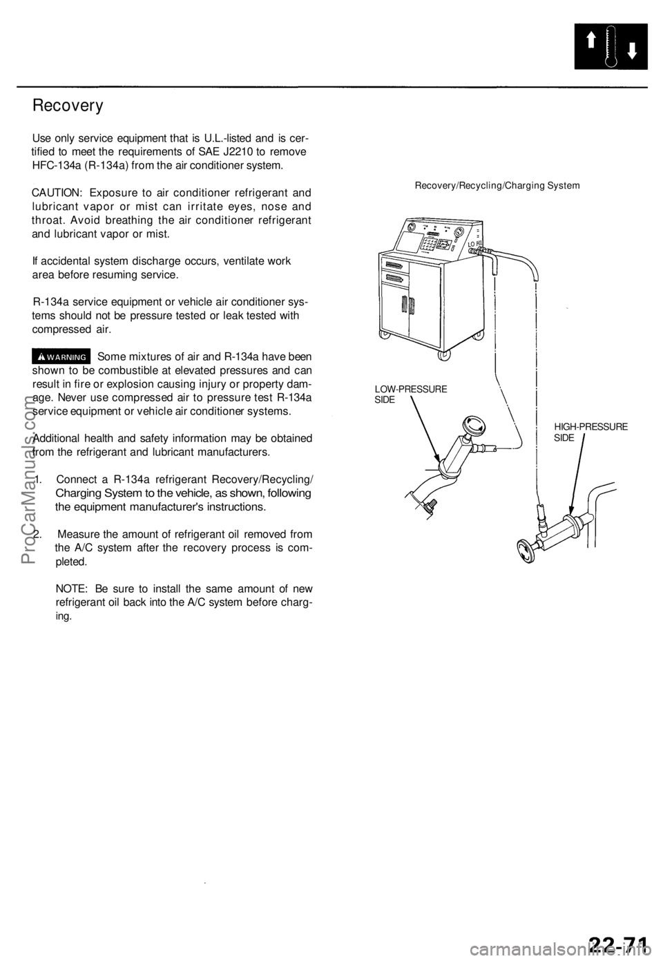
1. Connect a R-134a refrigerant Recovery/Recycling/
Charging System to the vehicle, as shown, following
the equipment manufacturer's instructions.
2. Measure the amount of refrigerant oil removed from
the A/C system after the recovery process is com-
pleted.
NOTE: Be sure to install the same amount of new
refrigerant oil back into the A/C system before charg-
ing.
Recovery/Recycling/Charging System
HIGH-PRESSURE
SIDE
LOW-PRESSURE
SIDEProCarManuals.com
Page 1522 of 1771
Compressor
Replacemen t
1. I f th e compresso r i s marginall y operable , ru n th e
engin e a t idl e speed , an d le t th e ai r conditione r
wor k fo r a fe w minutes , the n shu t th e engin e off .
2 . Disconnec t th e negativ e cabl e fro m th e battery .
3 . Recove r th e refrigeran t wit h a Recovery/Recycling /
Chargin g Syste m (se e pag e 22-71 ).
4 . Remov e th e intak e ai r duc t (se e sectio n 5) .
5 . Remov e th e A/ C compresso r bel t (se e pag e 22-78 ).
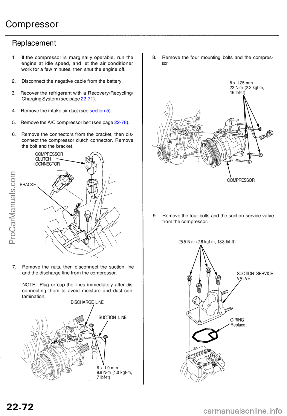
6 . Remov e th e connector s fro m th e bracket , the n dis -
connec t th e compresso r clutc h connector . Remov e
th e bol t an d th e bracket .
COMPRESSO R
CLUTC H
CONNECTO R
BRACKET
7. Remov e th e nuts , the n disconnec t th e suctio n lin e
an d th e discharg e lin e fro m th e compressor .
NOTE : Plu g o r ca p th e line s immediatel y afte r dis -
connectin g the m to avoi d moistur e an d dus t con -
tamination .
DISCHARG E LIN E
SUCTIO N LIN E
6 x 1. 0 m m9.8 N- m (1. 0 kgf-m ,
7 Ibf-ft )
8. Remov e th e fou r mountin g bolt s an d th e compres -
sor.
8 x 1.2 5 mm22 N- m (2. 2 kgf-m ,
1 6 Ibf-ft )
COMPRESSO R
9. Remov e th e fou r bolt s an d th e suctio n servic e valv e
fro m th e compressor .
25.5 N- m (2. 6 kgf-m , 18. 8 Ibf-ft )
SUCTIO N SERVIC E
VALV E
O-RIN G
Replace .
ProCarManuals.com
Page 1523 of 1771
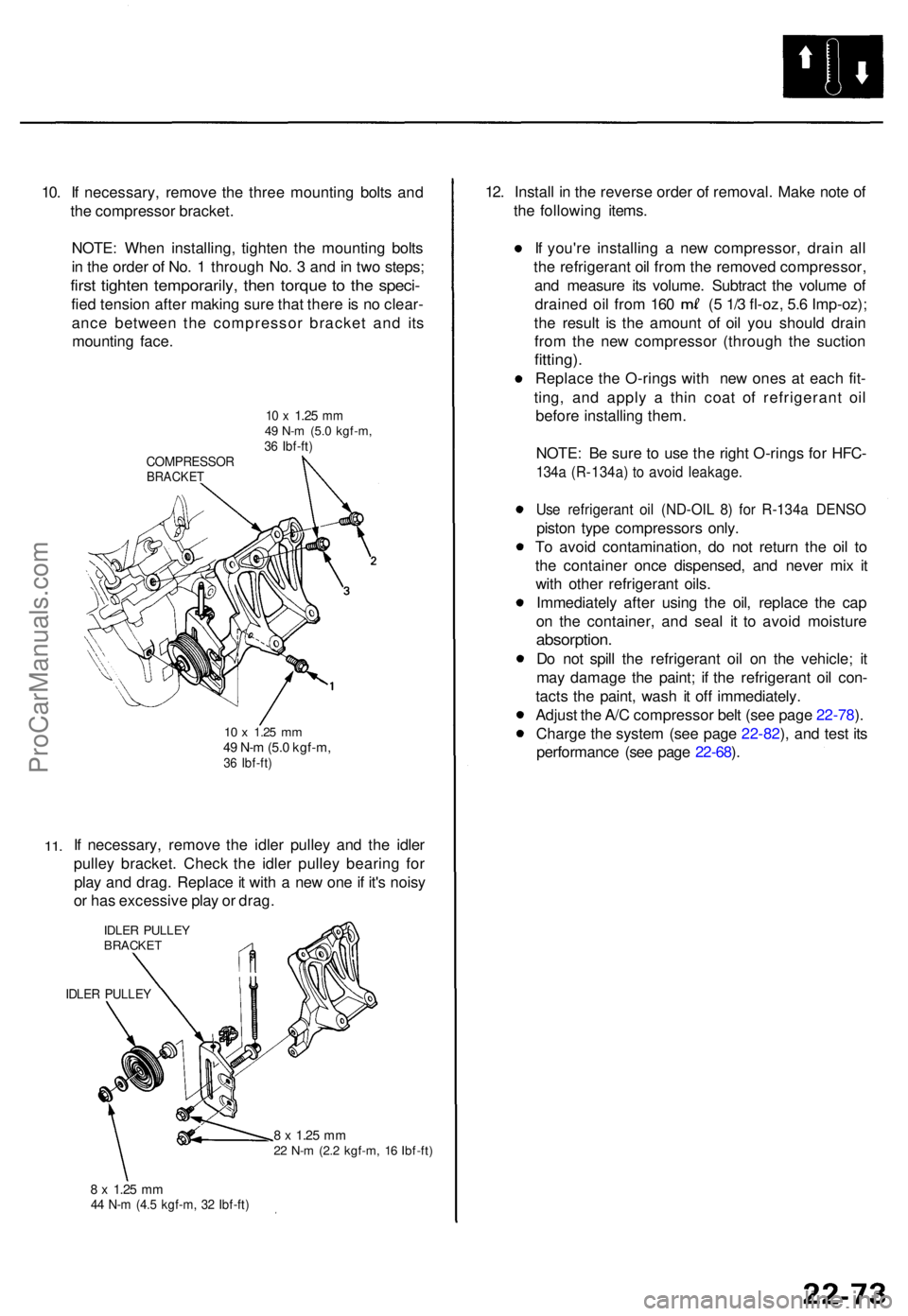
10. I f necessary , remov e th e thre e mountin g bolt s an d
th e compresso r bracket .
NOTE : Whe n installing , tighte n th e mountin g bolt s
i n th e orde r o f No . 1 throug h No . 3 an d in tw o steps ;
first tighte n temporarily , the n torqu e t o th e speci -
fied tensio n afte r makin g sur e tha t ther e is n o clear -
anc e betwee n th e compresso r bracke t an d it s
mountin g face .
10 x 1.2 5 mm49 N- m (5. 0 kgf-m ,36 Ibf-ft )COMPRESSO RBRACKET
11.
10 x 1.2 5 mm49 N- m (5. 0 kgf-m ,36 Ibf-ft )
If necessary , remov e th e idle r pulle y an d th e idle r
pulle y bracket . Chec k th e idle r pulle y bearin g fo r
pla y an d drag . Replac e it wit h a ne w on e if it' s nois y
o r ha s excessiv e pla y o r drag .
IDLER PULLE YBRACKE T
IDLER PULLE Y
8 x 1.2 5 mm22 N- m (2. 2 kgf-m , 1 6 Ibf-ft )
8 x 1.2 5 mm44 N- m (4. 5 kgf-m , 3 2 Ibf-ft )
12. Instal l i n th e revers e orde r o f removal . Mak e not e o f
th e followin g items .
I f you'r e installin g a ne w compressor , drai n al l
th e refrigeran t oi l fro m th e remove d compressor ,
an d measur e it s volume . Subtrac t th e volum e o f
draine d oi l fro m 16 0 ( 5 1/ 3 fl-oz , 5. 6 Imp-oz) ;
th e resul t i s th e amoun t o f oi l yo u shoul d drai n
fro m th e ne w compresso r (throug h th e suctio n
fitting).
Replac e th e O-ring s wit h ne w one s a t eac h fit -
ting , an d appl y a thi n coa t o f refrigeran t oi l
befor e installin g them .
NOTE : B e sur e t o us e th e righ t O-ring s fo r HFC -
134a (R-134a ) t o avoi d leakage .
Use refrigeran t oi l (ND-OI L 8 ) fo r R-134 a DENS O
piston typ e compressor s only .
T o avoi d contamination , d o no t retur n th e oi l t o
th e containe r onc e dispensed , an d neve r mi x i t
wit h othe r refrigeran t oils .
Immediatel y afte r usin g th e oil , replac e th e ca p
o n th e container , an d sea l i t t o avoi d moistur e
absorption .
Do no t spil l th e refrigeran t oi l o n th e vehicle ; i t
ma y damag e th e paint ; i f th e refrigeran t oi l con -
tact s th e paint , was h i t of f immediately .
Adjus t th e A/ C compresso r bel t (se e pag e 22-78 ).
Charg e th e syste m (se e pag e 22-82 ), an d tes t it s
performanc e (se e pag e 22-68 ).
ProCarManuals.com
Page 1524 of 1771
Compressor
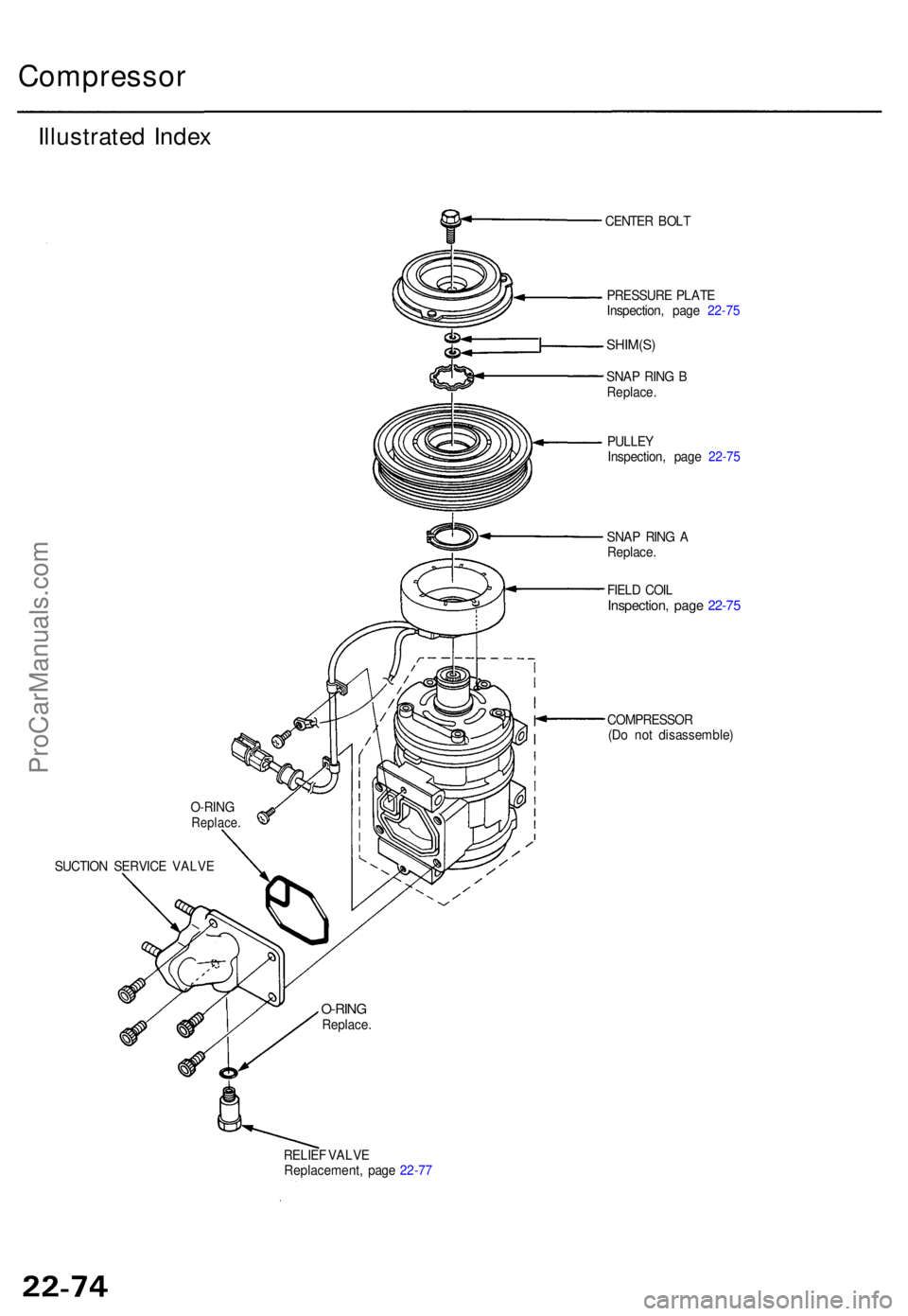
Illustrated Inde x
SUCTIO N SERVIC E VALV E CENTE
R BOL T
PRESSUR E PLAT E
Inspection , pag e 22-7 5
SHIM(S )
SNAP RIN G B
Replace .
PULLE Y
Inspection , pag e 22-7 5
SNA P RIN G A
Replace .
FIEL D COI L
Inspection , pag e 22-7 5
COMPRESSO R
(D o no t disassemble )
RELIE F VALV E
Replacement , pag e 22-7 7
O-RIN
G
Replace .
O-RINGReplace .
ProCarManuals.com
Page 1525 of 1771
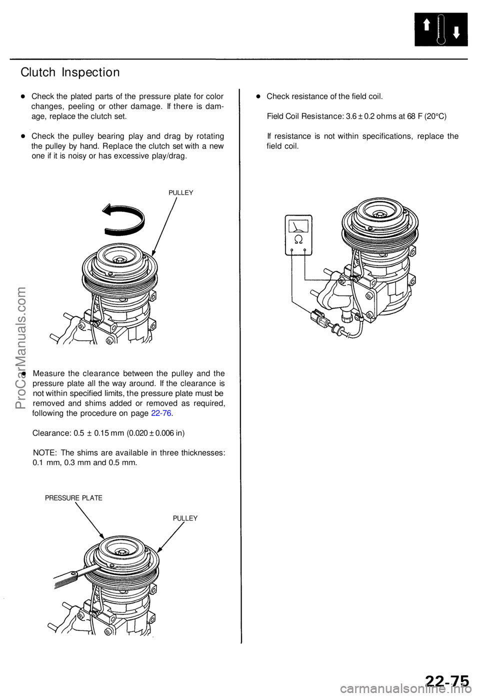
Clutch Inspectio n
Check th e plate d part s o f th e pressur e plat e fo r colo r
changes , peelin g o r othe r damage . I f ther e i s dam -
age , replac e th e clutc h set .
Chec k th e pulle y bearin g pla y an d dra g b y rotatin g
th e pulle y b y hand . Replac e th e clutc h se t wit h a ne w
on e if i t i s nois y o r ha s excessive play/drag.
PULLEY
Measur e th e clearanc e betwee n th e pulle y an d th e
pressur e plat e al l th e wa y around . I f th e clearanc e i s
no t withi n specifie d limits , th e pressur e plat e mus t b e
remove d an d shim s added or remove d a s required ,
followin g th e procedur e o n pag e 22-76 .
Clearance : 0. 5 ± 0.1 5 m m (0.02 0 ± 0.00 6 in )
NOTE : Th e shim s ar e availabl e i n thre e thicknesses :
0.1 mm , 0. 3 m m an d 0. 5 mm .
PRESSUR E PLAT E
PULLE Y
Check resistanc e o f th e fiel d coil .
Fiel d Coi l Resistance : 3. 6 ± 0. 2 ohm s a t 6 8 F (20°C )
I f resistanc e i s no t withi n specifications , replac e th e
fiel d coil .
ProCarManuals.com
Page 1526 of 1771
Compressor
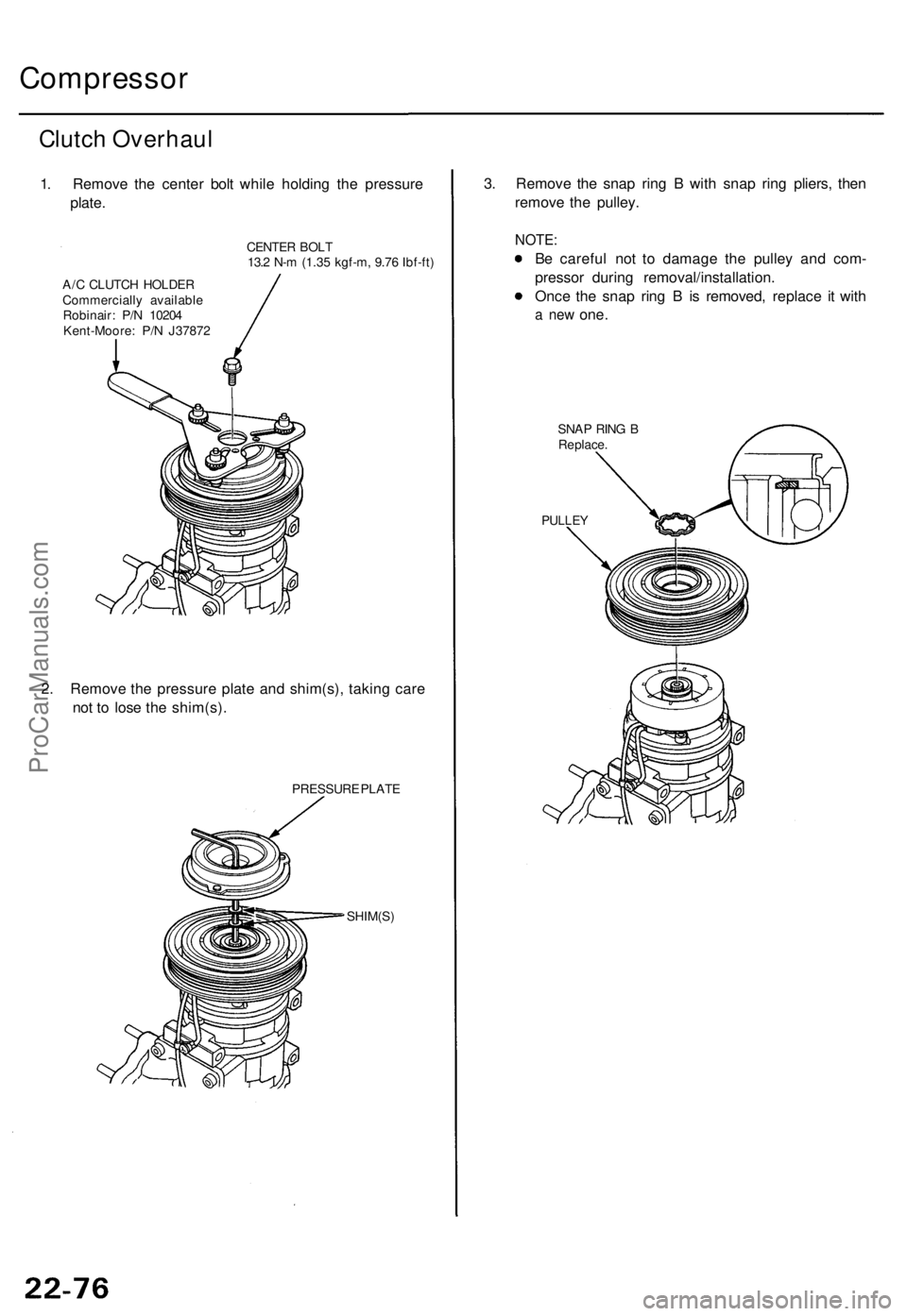
Clutch Overhau l
1. Remov e th e cente r bol t whil e holdin g th e pressur e
plate .
CENTE R BOL T
13. 2 N- m (1.3 5 kgf-m , 9.7 6 Ibf-ft )
A/ C CLUTC H HOLDE R
Commerciall y availabl e
Robinair : P/ N 1020 4
Kent-Moore : P/ N J3787 2
2. Remov e th e pressur e plat e an d shim(s) , takin g car e
no t t o los e th e shim(s) .
PRESSUR E PLAT E
SHIM(S )
3. Remov e th e sna p rin g B wit h sna p rin g pliers , the n
remov e th e pulley .
NOTE:
Be carefu l no t t o damag e th e pulle y an d com -
presso r durin g removal/installation .
Onc e th e sna p rin g B is removed , replac e i t wit h
a ne w one .
SNA P RIN G B
Replace .
PULLEY
ProCarManuals.com
Page 1527 of 1771
4.
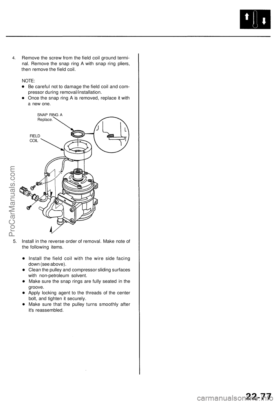
Remove the screw from the field coil ground termi-
nal. Remove the snap ring A with snap ring pliers,
then remove the field coil.
NOTE:
Be careful not to damage the field coil and com-
pressor during removal/installation.
Once the snap ring A is removed, replace it with
a new
one.
SNAP RING A
Replace.
FIELD
COIL
5. Install in the reverse order of removal. Make note of
the following items.
Install the field coil with the wire side facing
down (see above).
Clean the pulley and compressor sliding surfaces
with non-petroleum solvent.
Make sure the snap rings are fully seated in the
groove.
Apply locking agent to the threads of the center
bolt, and tighten it securely.
Make sure that the pulley turns smoothly after
it's reassembled.ProCarManuals.com
Page 1528 of 1771
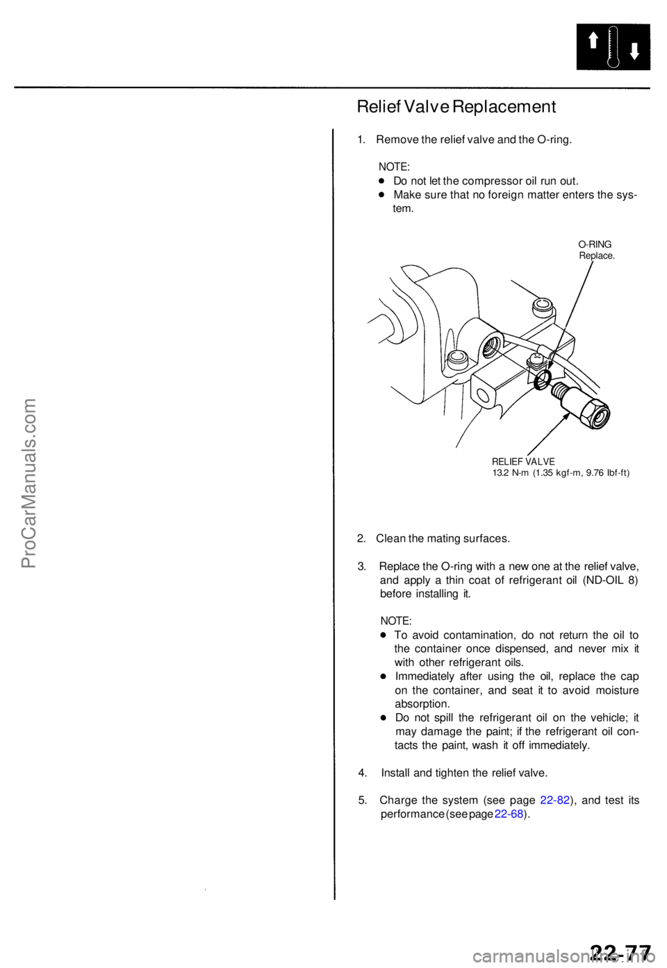
Relief Valv e Replacemen t
1. Remov e th e relie f valv e an d th e O-ring .
NOTE:
Do no t le t th e compresso r oi l ru n out .
Mak e sur e tha t n o foreig n matte r enter s th e sys -
tem.
O-RIN GReplace .
RELIEF VALV E13.2 N- m (1.3 5 kgf-m , 9.7 6 Ibf-ft )
2. Clea n th e matin g surfaces .
3 . Replac e th e O-rin g wit h a ne w on e a t th e relie f valve ,
an d appl y a thi n coa t o f refrigeran t oi l (ND-OI L 8 )
befor e installin g it .
NOTE :
To avoi d contamination , d o no t retur n th e oi l t o
th e containe r onc e dispensed , an d neve r mi x i t
wit h othe r refrigeran t oils .
Immediatel y afte r usin g th e oil , replac e th e cap
o n th e container , an d sea t i t t o avoi d moistur e
absorption .
D o no t spil l th e refrigeran t oi l o n th e vehicle ; i t
ma y damag e th e paint ; i f th e refrigeran t oi l con -
tact s th e paint , was h i t of f immediately .
4 . Instal l an d tighte n th e relie f valve .
5 . Charg e th e syste m (se e pag e 22-82 ), an d tes t it s
performanc e (se e pag e 22-68 ).
ProCarManuals.com
Page 1529 of 1771
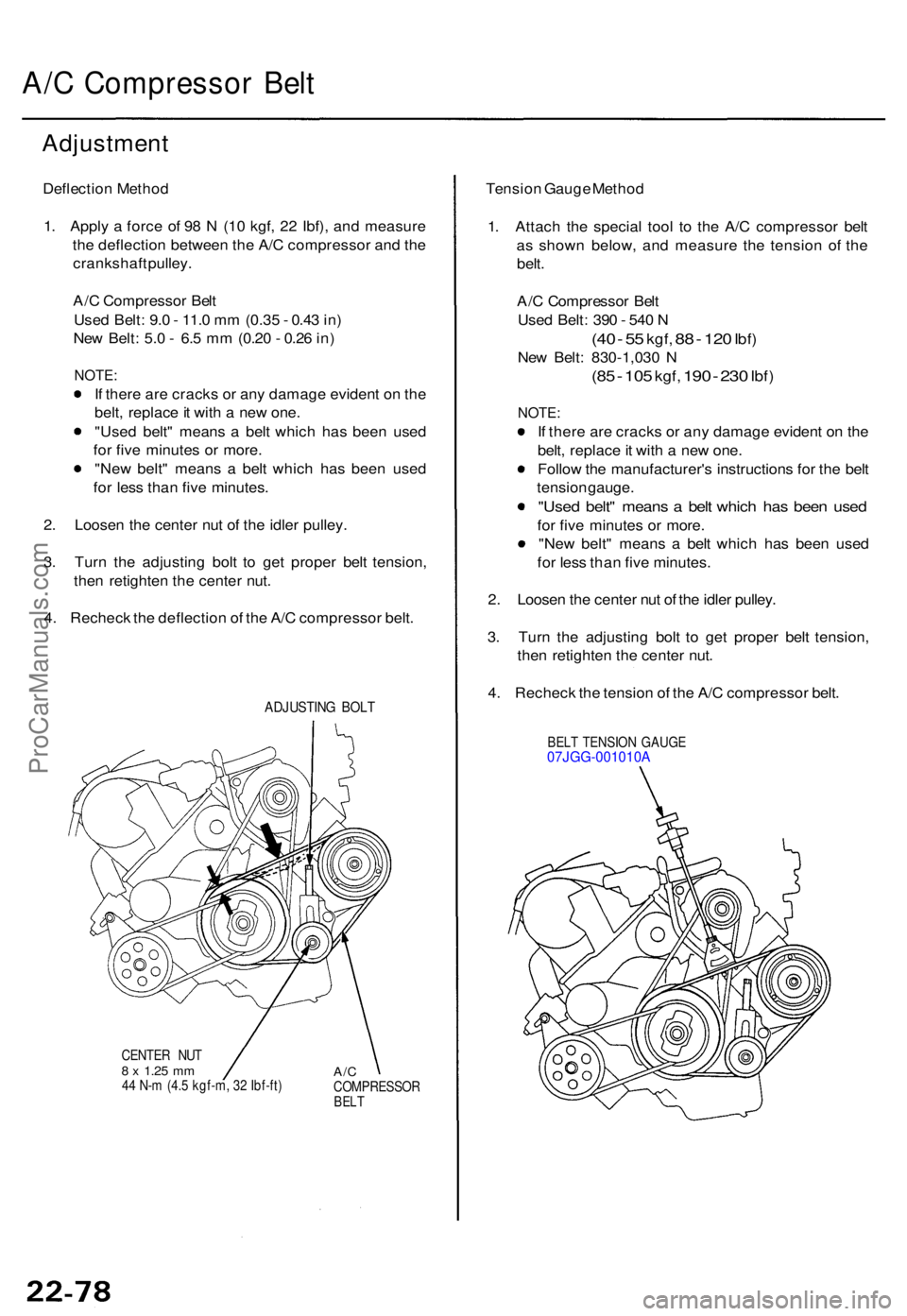
A/C Compresso r Bel t
Adjustmen t
Deflection Metho d
1 . Appl y a forc e o f 9 8 N (1 0 kgf , 2 2 Ibf) , an d measur e
th e deflectio n betwee n th e A/ C compresso r an d th e
crankshaf t pulley .
A/ C Compresso r Bel t
Use d Belt : 9. 0 - 11. 0 m m (0.3 5 - 0.4 3 in )
Ne w Belt : 5. 0 - 6. 5 m m (0.2 0 - 0.2 6 in )
NOTE :
If ther e ar e crack s o r an y damag e eviden t o n th e
belt , replac e it wit h a ne w one .
"Use d belt " mean s a bel t whic h ha s bee n use d
fo r fiv e minute s o r more .
"Ne w belt " mean s a bel t whic h ha s bee n use d
fo r les s tha n fiv e minutes .
2 . Loose n th e cente r nu t o f th e idle r pulley .
3 . Tur n th e adjustin g bol t t o ge t prope r bel t tension ,
the n retighte n th e cente r nut .
4 . Rechec k th e deflectio n o f th e A/ C compresso r belt .
ADJUSTIN G BOL T
CENTE R NU T8 x 1.2 5 mm44 N- m (4. 5 kgf-m , 3 2 Ibf-ft )A/CCOMPRESSO RBELT
Tensio n Gaug e Metho d
1 . Attac h th e specia l too l t o th e A/ C compresso r bel t
a s show n below , an d measur e th e tensio n of the
belt .
A/ C Compresso r Bel t
Use d Belt : 39 0 - 54 0 N
(4 0 - 5 5 kgf , 88 - 12 0 Ibf )
New Belt : 830-1,03 0 N
(8 5 - 10 5 kgf , 190 - 230 Ibf )
NOTE :
If ther e ar e crack s o r an y damag e eviden t o n th e
belt , replac e it wit h a ne w one .
Follo w th e manufacturer' s instruction s fo r th e bel t
tensio n gauge .
"Used belt " mean s a bel t whic h ha s bee n use d
for fiv e minute s o r more .
"Ne w belt " mean s a bel t whic h ha s bee n use d
fo r les s tha n fiv e minutes .
2 . Loose n th e cente r nu t o f th e idle r pulley .
3 . Tur n th e adjustin g bol t t o ge t prope r bel t tension ,
the n retighte n th e cente r nut .
4 . Rechec k th e tensio n o f th e A/ C compresso r belt .
BEL T TENSIO N GAUG E07JGG-001010 A
ProCarManuals.com
Page 1530 of 1771
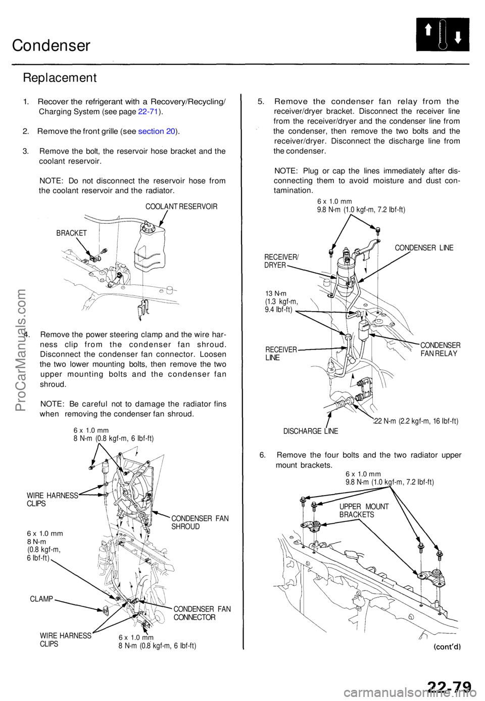
Condenser
Replacemen t
1. Recove r th e refrigeran t wit h a Recovery/Recycling /
Charging Syste m (se e pag e 22-71 ).
2 . Remov e th e fron t grill e (se e sectio n 20 ).
3 . Remov e th e bolt , th e reservoi r hos e bracke t an d th e
coolan t reservoir .
NOTE : D o no t disconnec t th e reservoi r hos e fro m
th e coolan t reservoi r an d th e radiator .
COOLAN T RESERVOI R
BRACKET
4. Remov e th e powe r steerin g clam p an d th e wir e har -
nes s cli p fro m th e condense r fa n shroud .
Disconnec t th e condense r fa n connector . Loose n
th e tw o lowe r mountin g bolts , the n remov e th e tw o
uppe r mountin g bolt s an d th e condense r fa n
shroud .
NOTE : B e carefu l no t t o damag e th e radiato r fin s
whe n removin g th e condense r fa n shroud .
6 x 1. 0 m m8 N- m (0. 8 kgf-m , 6 Ibf-ft )
WIR E HARNES S
CLIPS
6 x 1. 0 m m8 N- m(0.8 kgf-m ,
6 Ibf-ft )
CLAM P
WIR E HARNES S
CLIP S CONDENSE
R FA N
SHROU D
CONDENSE R FA N
CONNECTO R
6 x 1. 0 m m8 N- m (0. 8 kgf-m , 6 Ibf-ft )
5. Remov e th e condense r fa n rela y fro m th e
receiver/drye r bracket . Disconnec t th e receive r lin e
fro m th e receiver/drye r an d th e condense r lin e fro m
th e condenser , the n remov e th e tw o bolt s an d th e
receiver/dryer . Disconnec t th e discharg e lin e fro m
th e condenser .
NOTE : Plu g o r ca p th e line s immediatel y afte r dis -
connectin g the m to avoi d moistur e an d dus t con -
tamination .
6 x 1. 0 m m9.8 N- m (1. 0 kgf-m , 7. 2 Ibf-ft )
RECEIVER /DRYER
13 N- m(1.3 kgf-m ,
9. 4 Ibf-ft )
RECEIVE RLINE
CONDENSE R LIN E
CONDENSE R
FA N RELA Y
2 2 N- m (2. 2 kgf-m , 1 6 Ibf-ft )
DISCHARG E LIN E
6. Remov e th e fou r bolt s an d th e tw o radiato r uppe r
moun t brackets .
6 x 1. 0 m m9.8 N- m (1. 0 kgf-m , 7. 2 Ibf-ft )
UPPE R MOUN T
BRACKET S
ProCarManuals.com