DODGE NEON 1999 Service Repair Manual
Manufacturer: DODGE, Model Year: 1999,
Model line: NEON,
Model: DODGE NEON 1999
Pages: 1200, PDF Size: 35.29 MB
DODGE NEON 1999 Service Repair Manual
NEON 1999
DODGE
DODGE
https://www.carmanualsonline.info/img/12/56911/w960_56911-0.png
DODGE NEON 1999 Service Repair Manual
Trending: transmission fluid, engine oil capacity, open hood, drain bolt, key fob, battery capacity, clock
Page 1031 of 1200
DETERMINING SHIM THICKNESS
Shim thickness need be determined only if any of
the following parts are replaced:
²Transaxle case
²Transfer shaft
²Transfer shaft gear
²Transfer shaft bearings
²Governor support retainer
²Transfer shaft bearing retainer
²Retainer snap ring
²Governor support
Refer to Bearing Adjustment Procedure in rear of
this section to determine proper shim thickness.STIRRUP AND STRAP INSTALLATION
Once bearing shim selection has been adjusted,
install stirrup and strap assembly onto transfer gear.
NOTE: Once the stirrup assembly is positioned
onto the transfer gear, it is necessary to ªclockº the
stirrup against the flats of the transfer gear retain-
ing nut.
(1) Position the stirrup on the transfer gear.
(2) Position strap.
(3) Install retaining bolts into transfer gear. Fin-
ger±tighten bolts.
(4) Turn stirrup clockwise against the flats of the
transfer gear retaining nut.
(5) Tighten retaining bolts to 23 N´m (200 in. lbs.).
(6) Bend tabs of strap up against ªflatsºof retain-
ing bolts.
ASSEMBLY
To install transfer shaft, reverse the above proce-
dure.
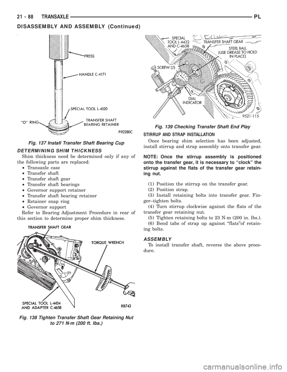
Fig. 137 Install Transfer Shaft Bearing Cup
Fig. 138 Tighten Transfer Shaft Gear Retaining Nut
to 271 N´m (200 ft. lbs.)
Fig. 139 Checking Transfer Shaft End Play
21 - 88 TRANSAXLEPL
DISASSEMBLY AND ASSEMBLY (Continued)
Page 1032 of 1200
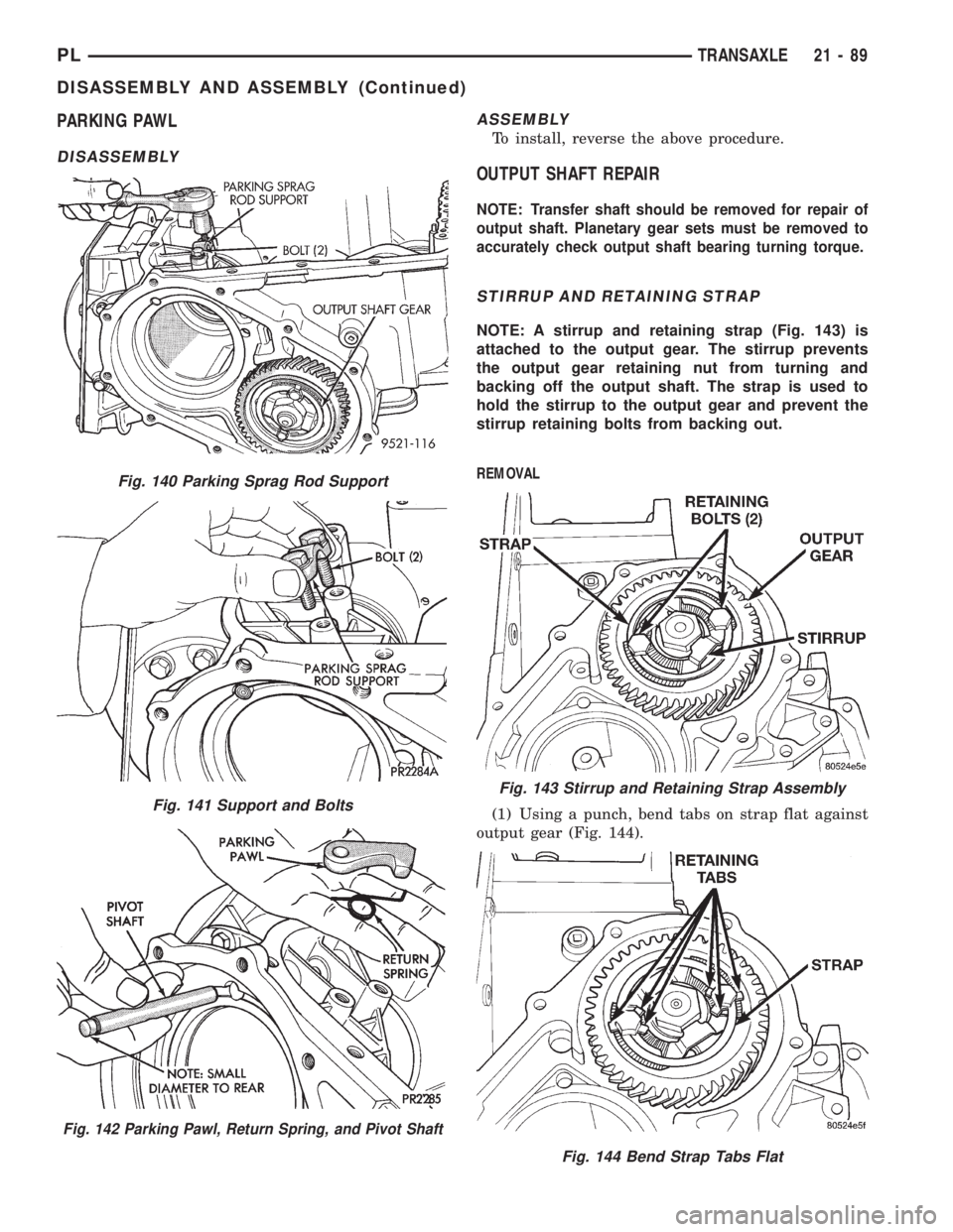
PARKING PAWL
DISASSEMBLYASSEMBLY
To install, reverse the above procedure.
OUTPUT SHAFT REPAIR
NOTE: Transfer shaft should be removed for repair of
output shaft. Planetary gear sets must be removed to
accurately check output shaft bearing turning torque.
STIRRUP AND RETAINING STRAP
NOTE: A stirrup and retaining strap (Fig. 143) is
attached to the output gear. The stirrup prevents
the output gear retaining nut from turning and
backing off the output shaft. The strap is used to
hold the stirrup to the output gear and prevent the
stirrup retaining bolts from backing out.
REMOVAL
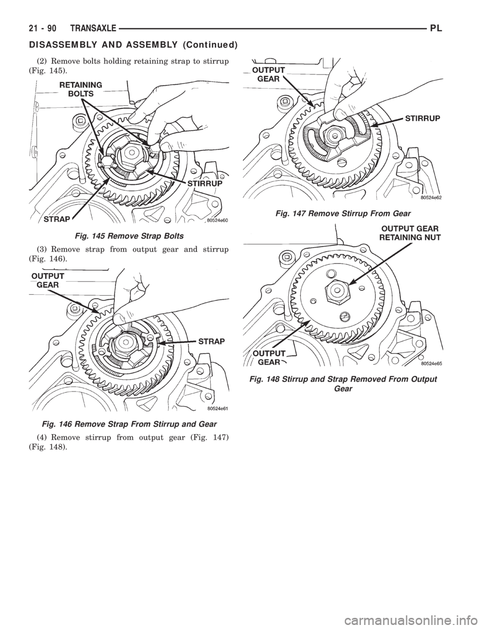
(1) Using a punch, bend tabs on strap flat against
output gear (Fig. 144).
Fig. 140 Parking Sprag Rod Support
Fig. 141 Support and Bolts
Fig. 142 Parking Pawl, Return Spring, and Pivot Shaft
Fig. 143 Stirrup and Retaining Strap Assembly
Fig. 144 Bend Strap Tabs Flat
PLTRANSAXLE 21 - 89
DISASSEMBLY AND ASSEMBLY (Continued)
Page 1033 of 1200
(2) Remove bolts holding retaining strap to stirrup
(Fig. 145).
(3) Remove strap from output gear and stirrup
(Fig. 146).
(4) Remove stirrup from output gear (Fig. 147)
(Fig. 148).
Fig. 145 Remove Strap Bolts
Fig. 146 Remove Strap From Stirrup and Gear
Fig. 147 Remove Stirrup From Gear
Fig. 148 Stirrup and Strap Removed From Output
Gear
21 - 90 TRANSAXLEPL
DISASSEMBLY AND ASSEMBLY (Continued)
Page 1034 of 1200
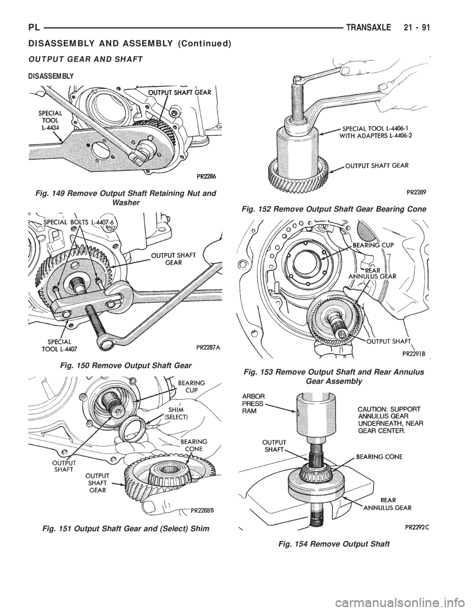
OUTPUT GEAR AND SHAFT
DISASSEMBLY
Fig. 149 Remove Output Shaft Retaining Nut and
Washer
Fig. 150 Remove Output Shaft Gear
Fig. 151 Output Shaft Gear and (Select) Shim
Fig. 152 Remove Output Shaft Gear Bearing Cone
Fig. 153 Remove Output Shaft and Rear Annulus
Gear Assembly
Fig. 154 Remove Output Shaft
PLTRANSAXLE 21 - 91
DISASSEMBLY AND ASSEMBLY (Continued)
Page 1035 of 1200
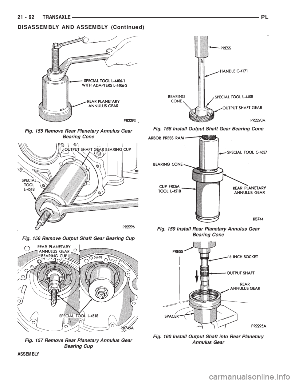
ASSEMBLY
Fig. 155 Remove Rear Planetary Annulus Gear
Bearing Cone
Fig. 156 Remove Output Shaft Gear Bearing Cup
Fig. 157 Remove Rear Planetary Annulus Gear
Bearing Cup
Fig. 158 Install Output Shaft Gear Bearing Cone
Fig. 159 Install Rear Planetary Annulus Gear
Bearing Cone
Fig. 160 Install Output Shaft into Rear Planetary
Annulus Gear
21 - 92 TRANSAXLEPL
DISASSEMBLY AND ASSEMBLY (Continued)
Page 1036 of 1200
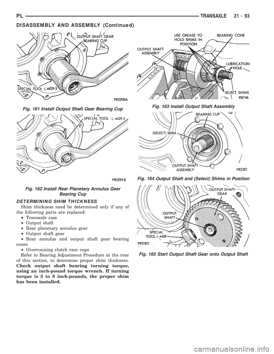
DETERMINING SHIM THICKNESS
Shim thickness need be determined only if any of
the following parts are replaced:
²Transaxle case
²Output shaft
²Rear planetary annulus gear
²Output shaft gear
²Rear annulus and output shaft gear bearing
cones
²Overrunning clutch race cups
Refer to Bearing Adjustment Procedure at the rear
of this section, to determine proper shim thickness.
Check output shaft bearing turning torque,
using an inch-pound torque wrench. If turning
torque is 3 to 8 inch-pounds, the proper shim
has been installed.
Fig. 161 Install Output Shaft Gear Bearing Cup
Fig. 162 Install Rear Planetary Annulus Gear
Bearing Cup
Fig. 163 Install Output Shaft Assembly
Fig. 164 Output Shaft and (Select) Shims in Position
Fig. 165 Start Output Shaft Gear onto Output Shaft
PLTRANSAXLE 21 - 93
DISASSEMBLY AND ASSEMBLY (Continued)
Page 1037 of 1200
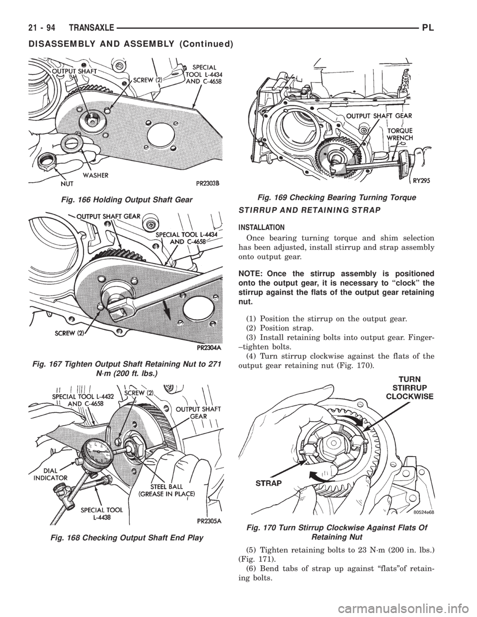
STIRRUP AND RETAINING STRAP
INSTALLATION
Once bearing turning torque and shim selection
has been adjusted, install stirrup and strap assembly
onto output gear.
NOTE: Once the stirrup assembly is positioned
onto the output gear, it is necessary to ªclockº the
stirrup against the flats of the output gear retaining
nut.
(1) Position the stirrup on the output gear.
(2) Position strap.
(3) Install retaining bolts into output gear. Finger-
±tighten bolts.
(4) Turn stirrup clockwise against the flats of the
output gear retaining nut (Fig. 170).
(5) Tighten retaining bolts to 23 N´m (200 in. lbs.)
(Fig. 171).
(6) Bend tabs of strap up against ªflatsºof retain-
ing bolts.
Fig. 166 Holding Output Shaft Gear
Fig. 167 Tighten Output Shaft Retaining Nut to 271
N´m (200 ft. lbs.)
Fig. 168 Checking Output Shaft End Play
Fig. 169 Checking Bearing Turning Torque
Fig. 170 Turn Stirrup Clockwise Against Flats Of
Retaining Nut
21 - 94 TRANSAXLEPL
DISASSEMBLY AND ASSEMBLY (Continued)
Page 1038 of 1200
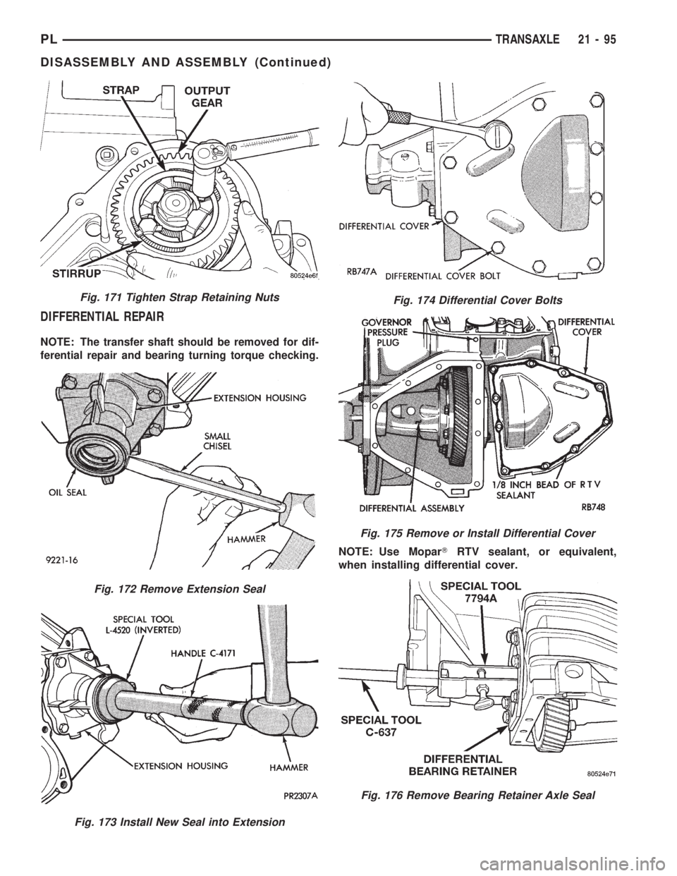
DIFFERENTIAL REPAIR
NOTE: The transfer shaft should be removed for dif-
ferential repair and bearing turning torque checking.
NOTE: Use MoparTRTV sealant, or equivalent,
when installing differential cover.
Fig. 171 Tighten Strap Retaining Nuts
Fig. 172 Remove Extension Seal
Fig. 173 Install New Seal into Extension
Fig. 174 Differential Cover Bolts
Fig. 175 Remove or Install Differential Cover
Fig. 176 Remove Bearing Retainer Axle Seal
PLTRANSAXLE 21 - 95
DISASSEMBLY AND ASSEMBLY (Continued)
Page 1039 of 1200
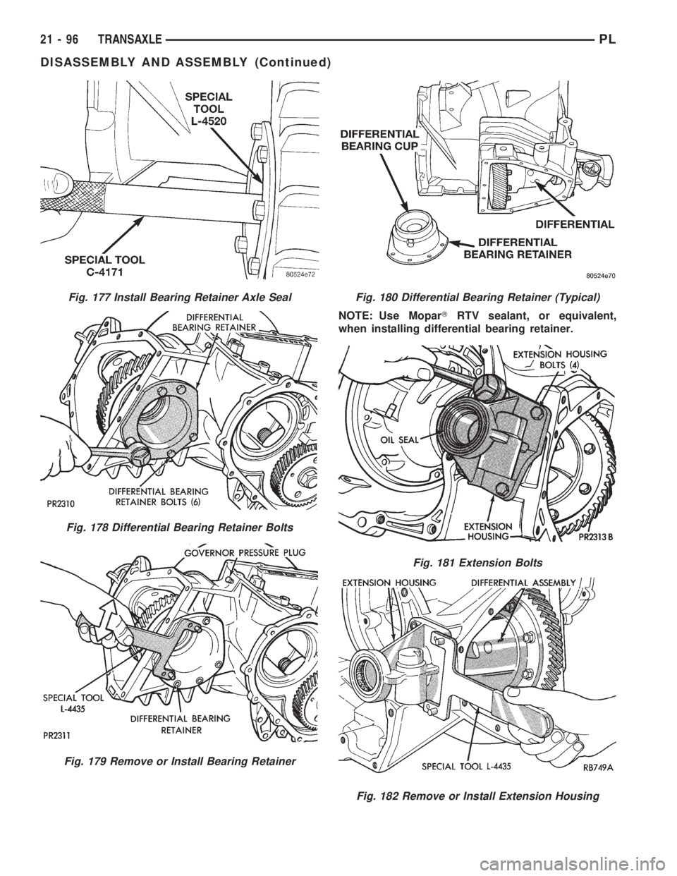
NOTE: Use MoparTRTV sealant, or equivalent,
when installing differential bearing retainer.
Fig. 177 Install Bearing Retainer Axle Seal
Fig. 178 Differential Bearing Retainer Bolts
Fig. 179 Remove or Install Bearing Retainer
Fig. 180 Differential Bearing Retainer (Typical)
Fig. 181 Extension Bolts
Fig. 182 Remove or Install Extension Housing
21 - 96 TRANSAXLEPL
DISASSEMBLY AND ASSEMBLY (Continued)
Page 1040 of 1200
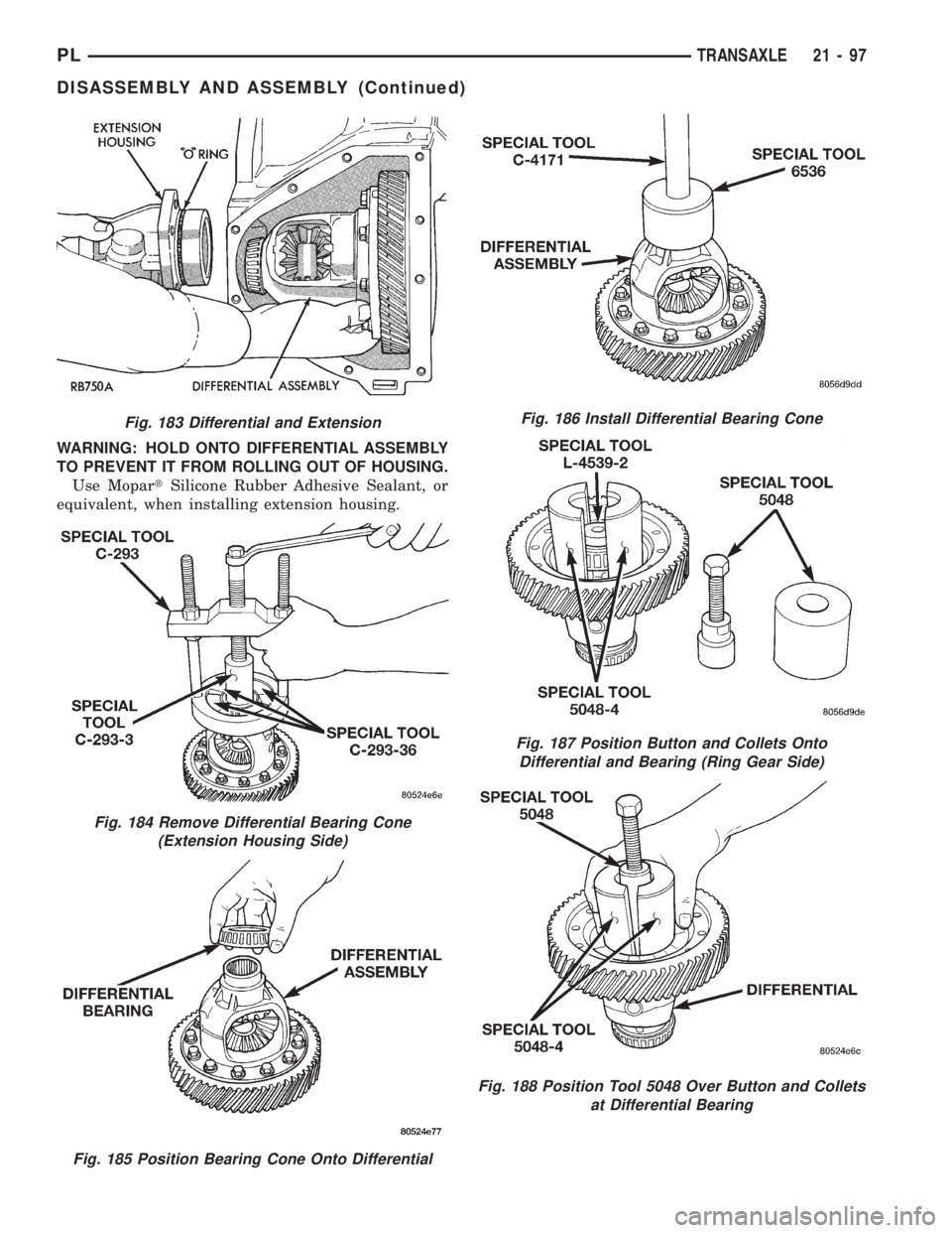
WARNING: HOLD ONTO DIFFERENTIAL ASSEMBLY
TO PREVENT IT FROM ROLLING OUT OF HOUSING.
Use MopartSilicone Rubber Adhesive Sealant, or
equivalent, when installing extension housing.
Fig. 183 Differential and Extension
Fig. 184 Remove Differential Bearing Cone
(Extension Housing Side)
Fig. 185 Position Bearing Cone Onto Differential
Fig. 186 Install Differential Bearing Cone
Fig. 187 Position Button and Collets Onto
Differential and Bearing (Ring Gear Side)
Fig. 188 Position Tool 5048 Over Button and Collets
at Differential Bearing
PLTRANSAXLE 21 - 97
DISASSEMBLY AND ASSEMBLY (Continued)
Trending: ignition, coolant reservoir, key fob, four wheel drive, fuel cap, spare wheel, low beam

