DODGE NEON 1999 Service Repair Manual
Manufacturer: DODGE, Model Year: 1999, Model line: NEON, Model: DODGE NEON 1999Pages: 1200, PDF Size: 35.29 MB
Page 881 of 1200
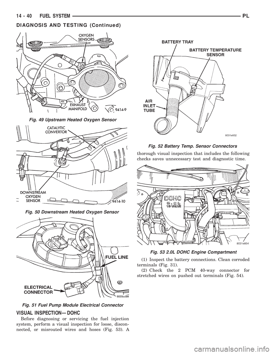
VISUAL INSPECTIONÐDOHC
Before diagnosing or servicing the fuel injection
system, perform a visual inspection for loose, discon-
nected, or misrouted wires and hoses (Fig. 53). Athorough visual inspection that includes the following
checks saves unnecessary test and diagnostic time.
(1) Inspect the battery connections. Clean corroded
terminals (Fig. 31).
(2) Check the 2 PCM 40-way connector for
stretched wires on pushed out terminals (Fig. 54).
Fig. 49 Upstream Heated Oxygen Sensor
Fig. 50 Downstream Heated Oxygen Sensor
Fig. 51 Fuel Pump Module Electrical Connector
Fig. 52 Battery Temp. Sensor Connectors
Fig. 53 2.0L DOHC Engine Compartment
14 - 40 FUEL SYSTEMPL
DIAGNOSIS AND TESTING (Continued)
Page 882 of 1200
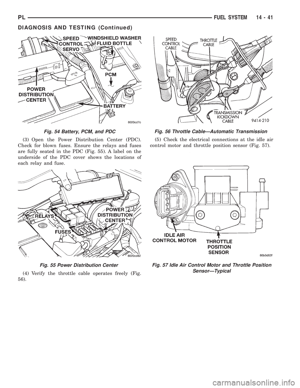
(3) Open the Power Distribution Center (PDC).
Check for blown fuses. Ensure the relays and fuses
are fully seated in the PDC (Fig. 55). A label on the
underside of the PDC cover shows the locations of
each relay and fuse.
(4) Verify the throttle cable operates freely (Fig.
56).(5) Check the electrical connections at the idle air
control motor and throttle position sensor (Fig. 57).
Fig. 54 Battery, PCM, and PDC
Fig. 55 Power Distribution Center
Fig. 56 Throttle CableÐAutomatic Transmission
Fig. 57 Idle Air Control Motor and Throttle Position
SensorÐTypical
PLFUEL SYSTEM 14 - 41
DIAGNOSIS AND TESTING (Continued)
Page 883 of 1200
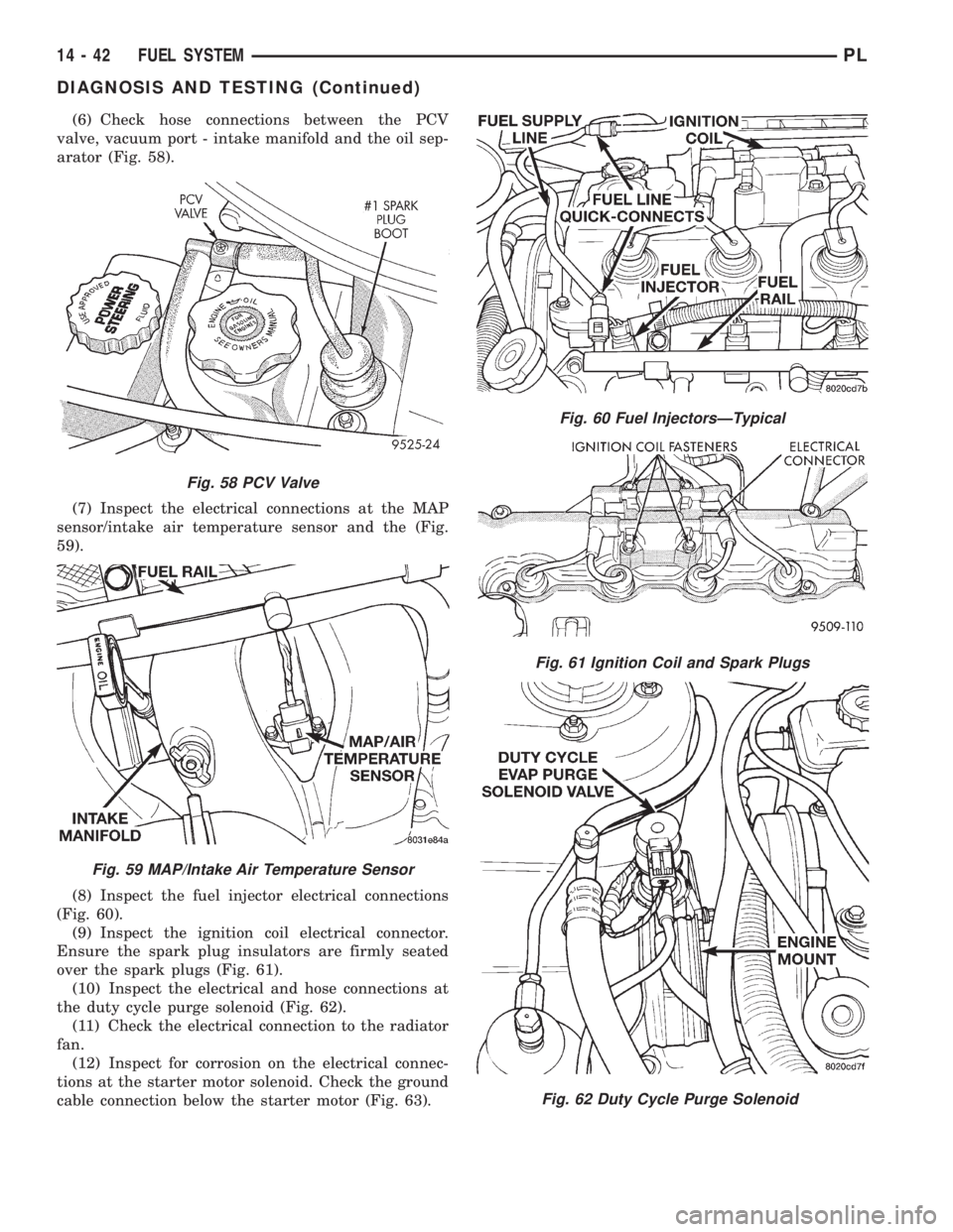
(6) Check hose connections between the PCV
valve, vacuum port - intake manifold and the oil sep-
arator (Fig. 58).
(7) Inspect the electrical connections at the MAP
sensor/intake air temperature sensor and the (Fig.
59).
(8) Inspect the fuel injector electrical connections
(Fig. 60).
(9) Inspect the ignition coil electrical connector.
Ensure the spark plug insulators are firmly seated
over the spark plugs (Fig. 61).
(10) Inspect the electrical and hose connections at
the duty cycle purge solenoid (Fig. 62).
(11) Check the electrical connection to the radiator
fan.
(12) Inspect for corrosion on the electrical connec-
tions at the starter motor solenoid. Check the ground
cable connection below the starter motor (Fig. 63).
Fig. 58 PCV Valve
Fig. 59 MAP/Intake Air Temperature Sensor
Fig. 60 Fuel InjectorsÐTypical
Fig. 61 Ignition Coil and Spark Plugs
Fig. 62 Duty Cycle Purge Solenoid
14 - 42 FUEL SYSTEMPL
DIAGNOSIS AND TESTING (Continued)
Page 884 of 1200
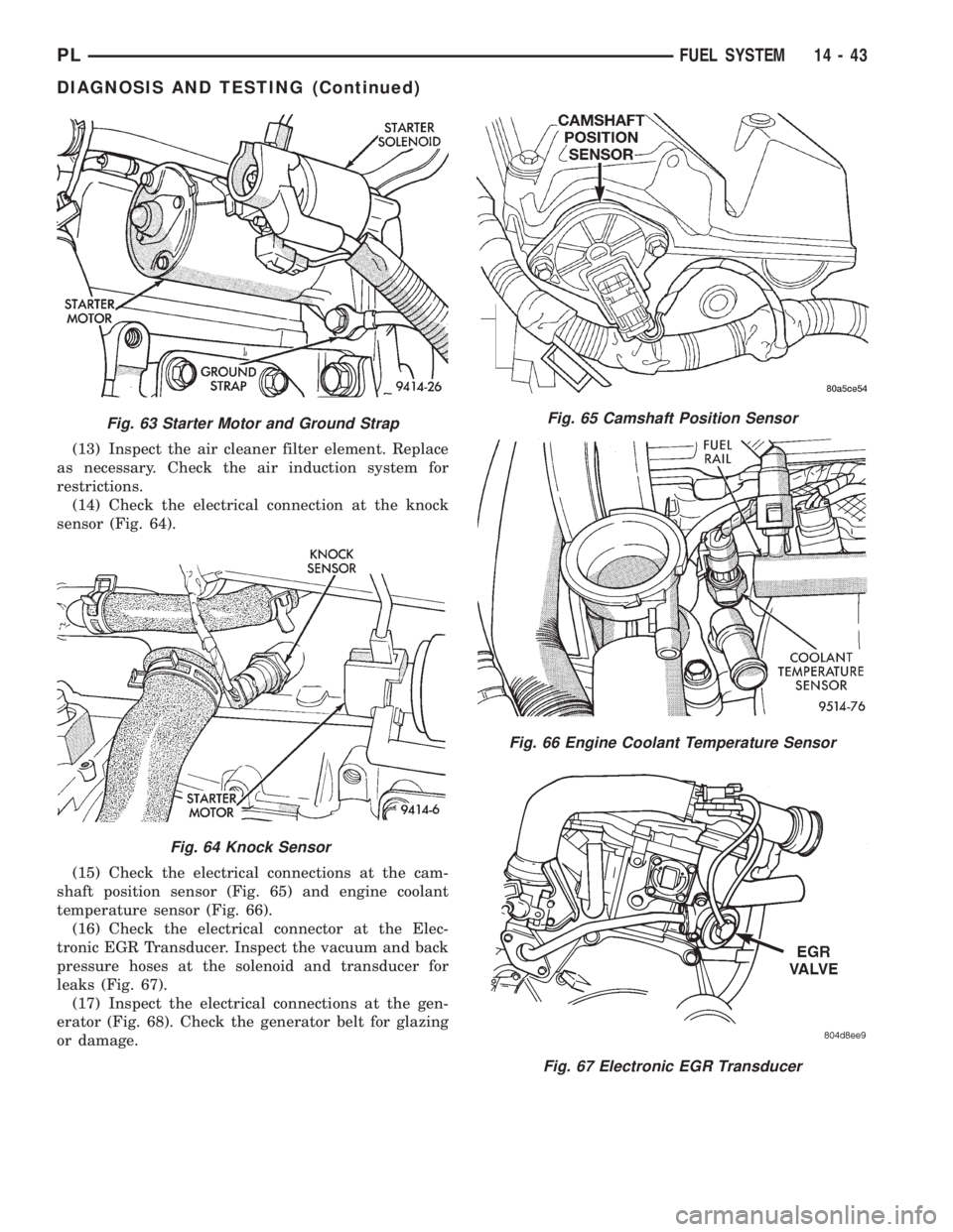
(13) Inspect the air cleaner filter element. Replace
as necessary. Check the air induction system for
restrictions.
(14) Check the electrical connection at the knock
sensor (Fig. 64).
(15) Check the electrical connections at the cam-
shaft position sensor (Fig. 65) and engine coolant
temperature sensor (Fig. 66).
(16) Check the electrical connector at the Elec-
tronic EGR Transducer. Inspect the vacuum and back
pressure hoses at the solenoid and transducer for
leaks (Fig. 67).
(17) Inspect the electrical connections at the gen-
erator (Fig. 68). Check the generator belt for glazing
or damage.
Fig. 63 Starter Motor and Ground Strap
Fig. 64 Knock Sensor
Fig. 65 Camshaft Position Sensor
Fig. 66 Engine Coolant Temperature Sensor
Fig. 67 Electronic EGR Transducer
PLFUEL SYSTEM 14 - 43
DIAGNOSIS AND TESTING (Continued)
Page 885 of 1200
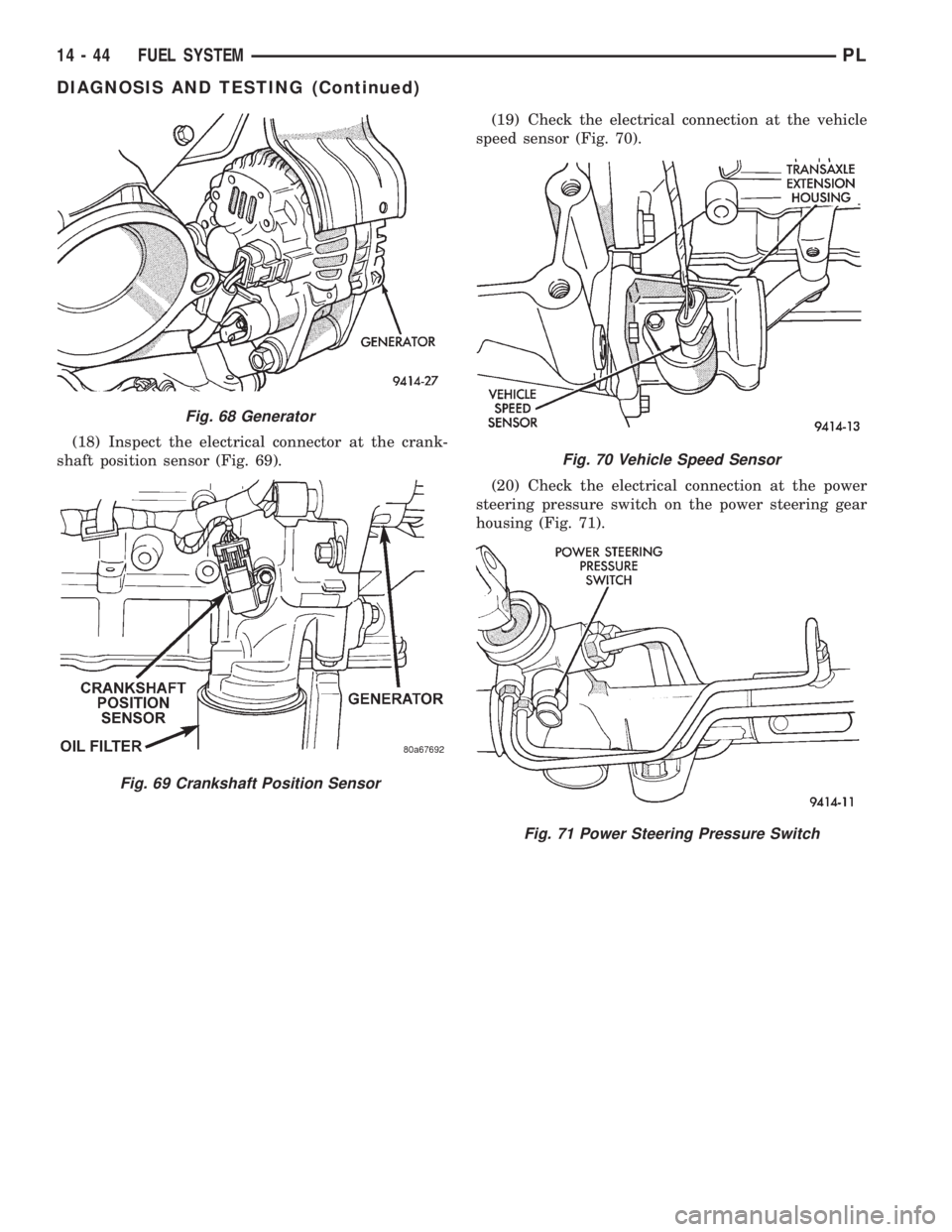
(18) Inspect the electrical connector at the crank-
shaft position sensor (Fig. 69).(19) Check the electrical connection at the vehicle
speed sensor (Fig. 70).
(20) Check the electrical connection at the power
steering pressure switch on the power steering gear
housing (Fig. 71).
Fig. 68 Generator
Fig. 69 Crankshaft Position Sensor
Fig. 70 Vehicle Speed Sensor
Fig. 71 Power Steering Pressure Switch
14 - 44 FUEL SYSTEMPL
DIAGNOSIS AND TESTING (Continued)
Page 886 of 1200
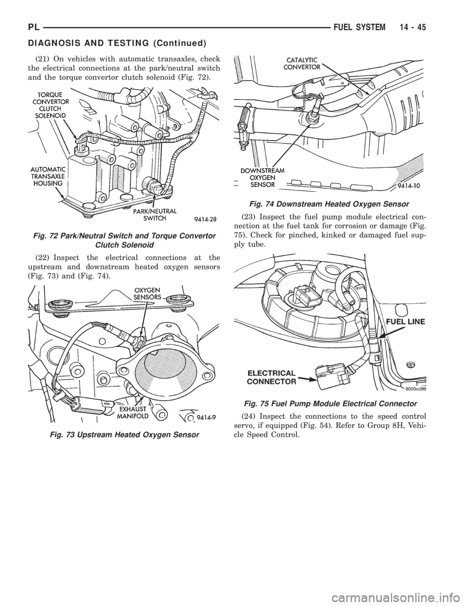
(21) On vehicles with automatic transaxles, check
the electrical connections at the park/neutral switch
and the torque convertor clutch solenoid (Fig. 72).
(22) Inspect the electrical connections at the
upstream and downstream heated oxygen sensors
(Fig. 73) and (Fig. 74).(23) Inspect the fuel pump module electrical con-
nection at the fuel tank for corrosion or damage (Fig.
75). Check for pinched, kinked or damaged fuel sup-
ply tube.
(24) Inspect the connections to the speed control
servo, if equipped (Fig. 54). Refer to Group 8H, Vehi-
cle Speed Control.
Fig. 72 Park/Neutral Switch and Torque Convertor
Clutch Solenoid
Fig. 73 Upstream Heated Oxygen Sensor
Fig. 74 Downstream Heated Oxygen Sensor
Fig. 75 Fuel Pump Module Electrical Connector
PLFUEL SYSTEM 14 - 45
DIAGNOSIS AND TESTING (Continued)
Page 887 of 1200
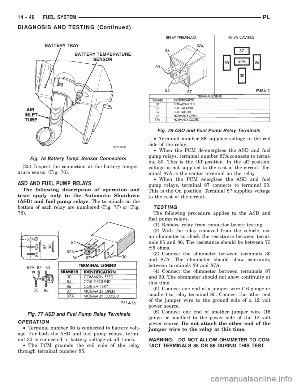
(25) Inspect the connection at the battery temper-
ature sensor (Fig. 76).
ASD AND FUEL PUMP RELAYS
The following description of operation and
tests apply only to the Automatic Shutdown
(ASD) and fuel pump relays. The terminals on the
bottom of each relay are numbered (Fig. 77) or (Fig.
78).
OPERATION
²Terminal number 30 is connected to battery volt-
age. For both the ASD and fuel pump relays, termi-
nal 30 is connected to battery voltage at all times.
²The PCM grounds the coil side of the relay
through terminal number 85.²Terminal number 86 supplies voltage to the coil
side of the relay.
²When the PCM de-energizes the ASD and fuel
pump relays, terminal number 87A connects to termi-
nal 30. This is the Off position. In the off position,
voltage is not supplied to the rest of the circuit. Ter-
minal 87A is the center terminal on the relay.
²When the PCM energizes the ASD and fuel
pump relays, terminal 87 connects to terminal 30.
This is the On position. Terminal 87 supplies voltage
to the rest of the circuit.
TESTING
The following procedure applies to the ASD and
fuel pump relays.
(1) Remove relay from connector before testing.
(2) With the relay removed from the vehicle, use
an ohmmeter to check the resistance between termi-
nals 85 and 86. The resistance should be between 75
65 ohms.
(3) Connect the ohmmeter between terminals 30
and 87A. The ohmmeter should show continuity
between terminals 30 and 87A.
(4) Connect the ohmmeter between terminals 87
and 30. The ohmmeter should not show continuity at
this time.
(5) Connect one end of a jumper wire (16 gauge or
smaller) to relay terminal 85. Connect the other end
of the jumper wire to the ground side of a 12 volt
power source.
(6) Connect one end of another jumper wire (16
gauge or smaller) to the power side of the 12 volt
power source.Do not attach the other end of the
jumper wire to the relay at this time.
WARNING: DO NOT ALLOW OHMMETER TO CON-
TACT TERMINALS 85 OR 86 DURING THIS TEST.
Fig. 76 Battery Temp. Sensor Connectors
Fig. 77 ASD and Fuel Pump Relay Terminals
Fig. 78 ASD and Fuel Pump Relay Terminals
14 - 46 FUEL SYSTEMPL
DIAGNOSIS AND TESTING (Continued)
Page 888 of 1200
(7) Attach the other end of the jumper wire to
relay terminal 86. This activates the relay. The ohm-
meter should now show continuity between relay ter-
minals 87 and 30. The ohmmeter should not show
continuity between relay terminals 87A and 30.
(8) Disconnect jumper wires.
(9) Replace the relay if it did not pass the continu-
ity and resistance tests. If the relay passed the tests,
it operates properly. Check the remainder of the ASD
and fuel pump relay circuits. Refer to group 8W, Wir-
ing Diagrams.
CAMSHAFT AND CRANKSHAFT POSITION SENSOR
Refer to Group 8D, Ignition for Diagnosis and Test-
ing of Camshaft and Crankshaft Sensors.
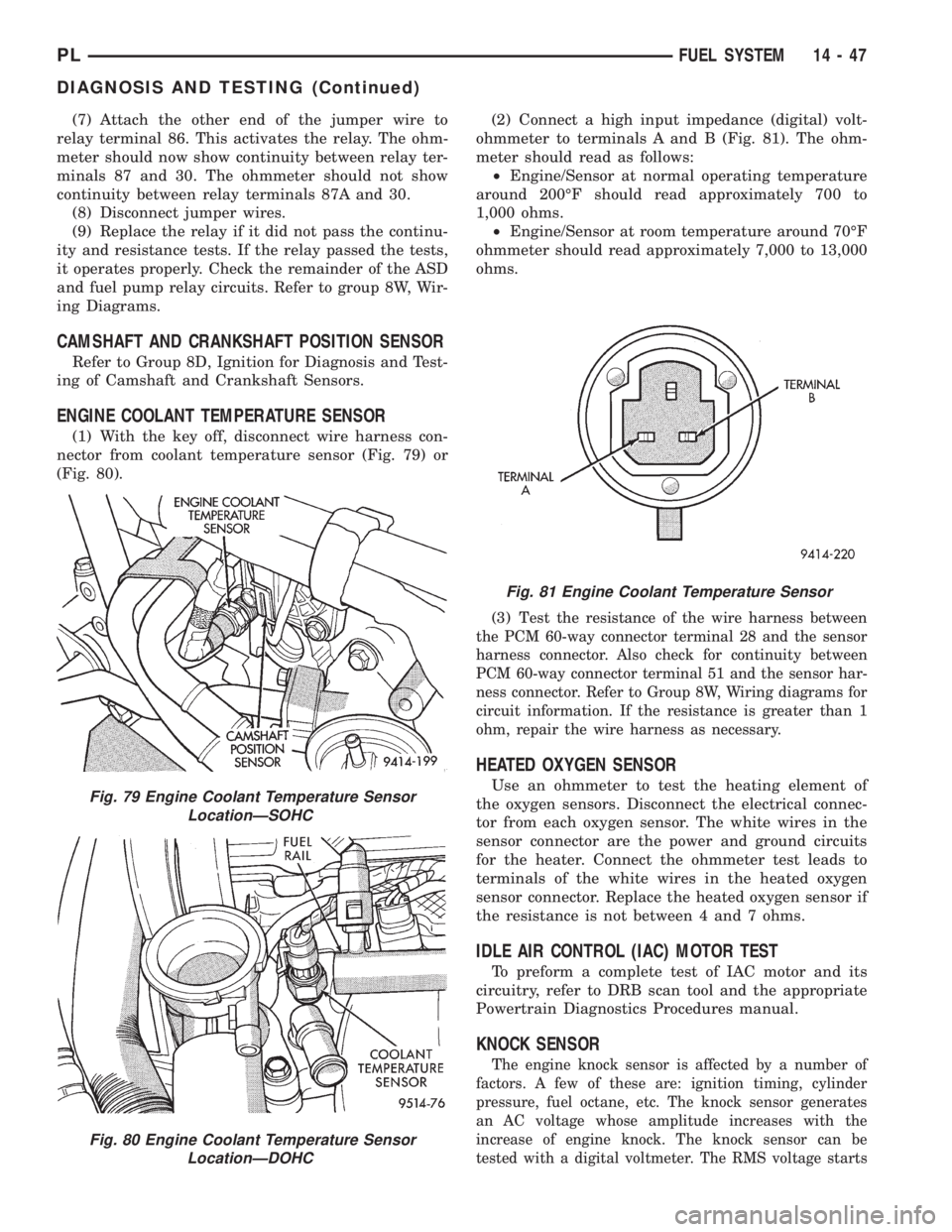
ENGINE COOLANT TEMPERATURE SENSOR
(1) With the key off, disconnect wire harness con-
nector from coolant temperature sensor (Fig. 79) or
(Fig. 80).(2) Connect a high input impedance (digital) volt-
ohmmeter to terminals A and B (Fig. 81). The ohm-
meter should read as follows:
²Engine/Sensor at normal operating temperature
around 200ÉF should read approximately 700 to
1,000 ohms.
²Engine/Sensor at room temperature around 70ÉF
ohmmeter should read approximately 7,000 to 13,000
ohms.
(3) T
est the resistance of the wire harness between
the PCM 60-way connector terminal 28 and the sensor
harness connector. Also check for continuity between
PCM 60-way connector terminal 51 and the sensor har-
ness connector. Refer to Group 8W, Wiring diagrams for
circuit information. If the resistance is greater than 1
ohm, repair the wire harness as necessary.
HEATED OXYGEN SENSOR
Use an ohmmeter to test the heating element of
the oxygen sensors. Disconnect the electrical connec-
tor from each oxygen sensor. The white wires in the
sensor connector are the power and ground circuits
for the heater. Connect the ohmmeter test leads to
terminals of the white wires in the heated oxygen
sensor connector. Replace the heated oxygen sensor if
the resistance is not between 4 and 7 ohms.
IDLE AIR CONTROL (IAC) MOTOR TEST
To preform a complete test of IAC motor and its
circuitry, refer to DRB scan tool and the appropriate
Powertrain Diagnostics Procedures manual.
KNOCK SENSOR
The engine knock sensor is affected by a number of
factors. A few of these are: ignition timing, cylinder
pressure, fuel octane, etc. The knock sensor generates
an AC voltage whose amplitude increases with the
increase of engine knock. The knock sensor can be
tested with a digital voltmeter. The RMS voltage starts
Fig. 79 Engine Coolant Temperature Sensor
LocationÐSOHC
Fig. 80 Engine Coolant Temperature Sensor
LocationÐDOHC
Fig. 81 Engine Coolant Temperature Sensor
PLFUEL SYSTEM 14 - 47
DIAGNOSIS AND TESTING (Continued)
Page 889 of 1200
at about 20mVac (at about 700 rpm) and increases to
approximately 600 mVac (5000 rpm). If the output falls
outside of this range a DTC will be set.
MANIFOLD ABSOLUTE PRESSURE (MAP) SENSOR
To perform a complete test of the MAP sensor and
its circuitry, refer to the DRB scan tool and appropri-
ate Powertrain Diagnostics Procedures manual. To
test the MAP sensor only, refer to the following:
CAUTION: When testing the MAP sensor, be sure
that the harness wires are not damaged by the test
meter probes.
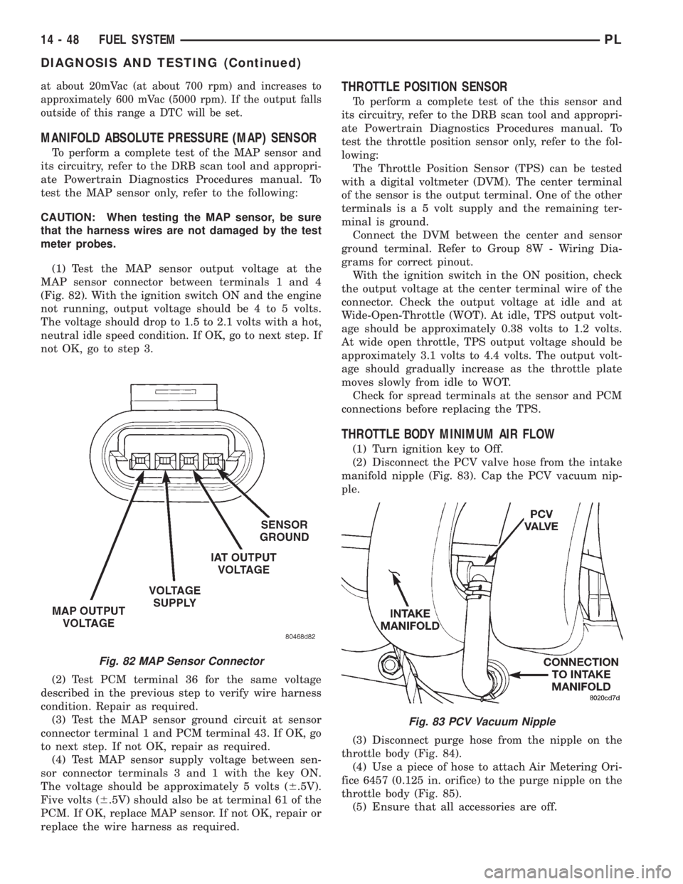
(1) Test the MAP sensor output voltage at the
MAP sensor connector between terminals 1 and 4
(Fig. 82). With the ignition switch ON and the engine
not running, output voltage should be 4 to 5 volts.
The voltage should drop to 1.5 to 2.1 volts with a hot,
neutral idle speed condition. If OK, go to next step. If
not OK, go to step 3.
(2) Test PCM terminal 36 for the same voltage
described in the previous step to verify wire harness
condition. Repair as required.
(3) Test the MAP sensor ground circuit at sensor
connector terminal 1 and PCM terminal 43. If OK, go
to next step. If not OK, repair as required.
(4) Test MAP sensor supply voltage between sen-
sor connector terminals 3 and 1 with the key ON.
The voltage should be approximately 5 volts (6.5V).
Five volts (6.5V) should also be at terminal 61 of the
PCM. If OK, replace MAP sensor. If not OK, repair or
replace the wire harness as required.
THROTTLE POSITION SENSOR
To perform a complete test of the this sensor and
its circuitry, refer to the DRB scan tool and appropri-
ate Powertrain Diagnostics Procedures manual. To
test the throttle position sensor only, refer to the fol-
lowing:
The Throttle Position Sensor (TPS) can be tested
with a digital voltmeter (DVM). The center terminal
of the sensor is the output terminal. One of the other
terminals is a 5 volt supply and the remaining ter-
minal is ground.
Connect the DVM between the center and sensor
ground terminal. Refer to Group 8W - Wiring Dia-
grams for correct pinout.
With the ignition switch in the ON position, check
the output voltage at the center terminal wire of the
connector. Check the output voltage at idle and at
Wide-Open-Throttle (WOT). At idle, TPS output volt-
age should be approximately 0.38 volts to 1.2 volts.
At wide open throttle, TPS output voltage should be
approximately 3.1 volts to 4.4 volts. The output volt-
age should gradually increase as the throttle plate
moves slowly from idle to WOT.
Check for spread terminals at the sensor and PCM
connections before replacing the TPS.
THROTTLE BODY MINIMUM AIR FLOW
(1) Turn ignition key to Off.
(2) Disconnect the PCV valve hose from the intake
manifold nipple (Fig. 83). Cap the PCV vacuum nip-
ple.
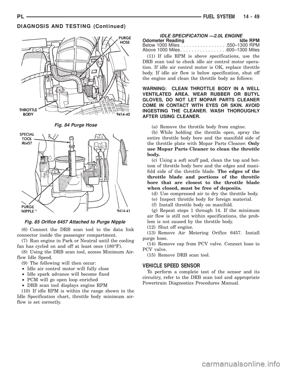
(3) Disconnect purge hose from the nipple on the
throttle body (Fig. 84).
(4) Use a piece of hose to attach Air Metering Ori-
fice 6457 (0.125 in. orifice) to the purge nipple on the
throttle body (Fig. 85).
(5) Ensure that all accessories are off.
Fig. 82 MAP Sensor Connector
Fig. 83 PCV Vacuum Nipple
14 - 48 FUEL SYSTEMPL
DIAGNOSIS AND TESTING (Continued)
Page 890 of 1200
(6) Connect the DRB scan tool to the data link
connector inside the passenger compartment.
(7) Run engine in Park or Neutral until the cooling
fan has cycled on and off at least once (180ÉF).
(8) Using the DRB scan tool, access Minimum Air-
flow Idle Speed.
(9) The following will then occur:
²Idle air control motor will fully close
²Idle spark advance will become fixed
²PCM will go open loop enriched
²DRB scan tool displays engine RPM
(10) If idle RPM is within the range shown in the
Idle Specification chart, throttle body minimum air-
flow is set correctly.
IDLE SPECIFICATION Ð2.0L ENGINEOdometer Reading Idle RPM
Below 1000 Miles.................550±1300 RPM
Above 1000 Miles.................600±1300 Miles
(11) If idle RPM is above specifications, use the
DRB scan tool to check idle air control motor opera-
tion. If idle air control motor is OK, replace throttle
body. If idle air flow is below specification, shut off
the engine and clean the throttle body as follows:
WARNING: CLEAN THROTTLE BODY IN A WELL
VENTILATED AREA. WEAR RUBBER OR BUTYL
GLOVES, DO NOT LET MOPAR PARTS CLEANER
COME IN CONTACT WITH EYES OR SKIN. AVOID
INGESTING THE CLEANER. WASH THOROUGHLY
AFTER USING CLEANER.
(a) Remove the throttle body from engine.
(b) While holding the throttle open, spray the
entire throttle body bore and the manifold side of
the throttle plate with Mopar Parts Cleaner.Only
use Mopar Parts Cleaner to clean the throttle
body.
(c) Using a soft scuff pad, clean the top and bot-
tom of throttle body bore and the edges and mani-
fold side of the throttle blade.The edges of the
throttle blade and portions of the throttle
bore that are closest to the throttle blade
when closed, must be free of deposits.
(d) Use compressed air to dry the throttle body.
(e) Inspect throttle body for foreign material.
(f) Install throttle body on manifold.
(g) Repeat steps 1 through 14. If the minimum
air flow is still not within specifications, the prob-
lem is not caused by the throttle body.
(12) Shut off engine.
(13) Remove Air Metering Orifice 6457. Install
purge hose.
(14) Remove cap from PCV valve. Connect hose to
PCV valve.
(15) Remove DRB scan tool.
VEHICLE SPEED SENSOR
To perform a complete test of the sensor and its
circuitry, refer to the DRB scan tool and appropriate
Powertrain Diagnostics Procedures Manual.
Fig. 84 Purge Hose
Fig. 85 Orifice 6457 Attached to Purge Nipple
PLFUEL SYSTEM 14 - 49
DIAGNOSIS AND TESTING (Continued)