DODGE NEON 1999 Service Repair Manual
Manufacturer: DODGE, Model Year: 1999, Model line: NEON, Model: DODGE NEON 1999Pages: 1200, PDF Size: 35.29 MB
Page 921 of 1200
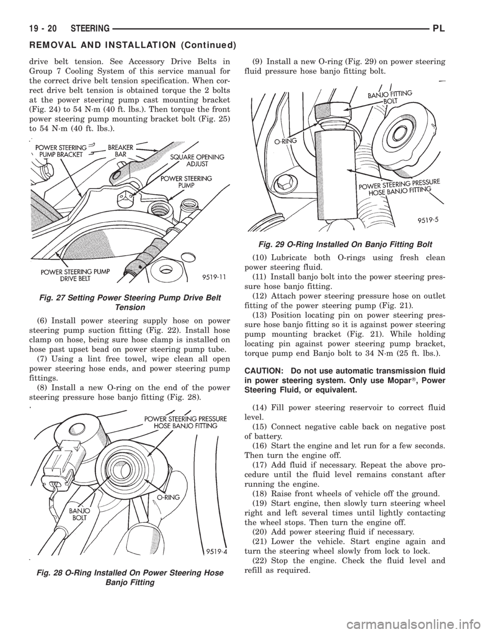
drive belt tension. See Accessory Drive Belts in
Group 7 Cooling System of this service manual for
the correct drive belt tension specification. When cor-
rect drive belt tension is obtained torque the 2 bolts
at the power steering pump cast mounting bracket
(Fig. 24) to 54 N´m (40 ft. lbs.). Then torque the front
power steering pump mounting bracket bolt (Fig. 25)
to 54 N´m (40 ft. lbs.).
(6) Install power steering supply hose on power
steering pump suction fitting (Fig. 22). Install hose
clamp on hose, being sure hose clamp is installed on
hose past upset bead on power steering pump tube.
(7) Using a lint free towel, wipe clean all open
power steering hose ends, and power steering pump
fittings.
(8) Install a new O-ring on the end of the power
steering pressure hose banjo fitting (Fig. 28).(9) Install a new O-ring (Fig. 29) on power steering
fluid pressure hose banjo fitting bolt.
(10) Lubricate both O-rings using fresh clean
power steering fluid.
(11) Install banjo bolt into the power steering pres-
sure hose banjo fitting.
(12) Attach power steering pressure hose on outlet
fitting of the power steering pump (Fig. 21).
(13) Position locating pin on power steering pres-
sure hose banjo fitting so it is against power steering
pump mounting bracket (Fig. 21). While holding
locating pin against power steering pump bracket,
torque pump end Banjo bolt to 34 N´m (25 ft. lbs.).
CAUTION: Do not use automatic transmission fluid
in power steering system. Only use MoparT, Power
Steering Fluid, or equivalent.
(14) Fill power steering reservoir to correct fluid
level.
(15) Connect negative cable back on negative post
of battery.
(16) Start the engine and let run for a few seconds.
Then turn the engine off.
(17) Add fluid if necessary. Repeat the above pro-
cedure until the fluid level remains constant after
running the engine.
(18) Raise front wheels of vehicle off the ground.
(19) Start engine, then slowly turn steering wheel
right and left several times until lightly contacting
the wheel stops. Then turn the engine off.
(20) Add power steering fluid if necessary.
(21) Lower the vehicle. Start engine again and
turn the steering wheel slowly from lock to lock.
(22) Stop the engine. Check the fluid level and
refill as required.
Fig. 27 Setting Power Steering Pump Drive Belt
Tension
Fig. 28 O-Ring Installed On Power Steering Hose
Banjo Fitting
Fig. 29 O-Ring Installed On Banjo Fitting Bolt
19 - 20 STEERINGPL
REMOVAL AND INSTALLATION (Continued)
Page 922 of 1200
(23) If the fluid is extremely foamy, allow the vehi-
cle to stand a few minutes and repeat the above pro-
cedure.
(24) After power steering pump is installed, check
for leaks at all hose connections and power steering
pump fittings.
POWER STEERING FLUID RESERVOIR
REMOVE
(1) Raise vehicle on jack stands or on a frame con-
tact type hoist. See Hoisting in the Lubrication And
Maintenance Section of this service manual for the
required lifting procedure to be used for this vehicle.
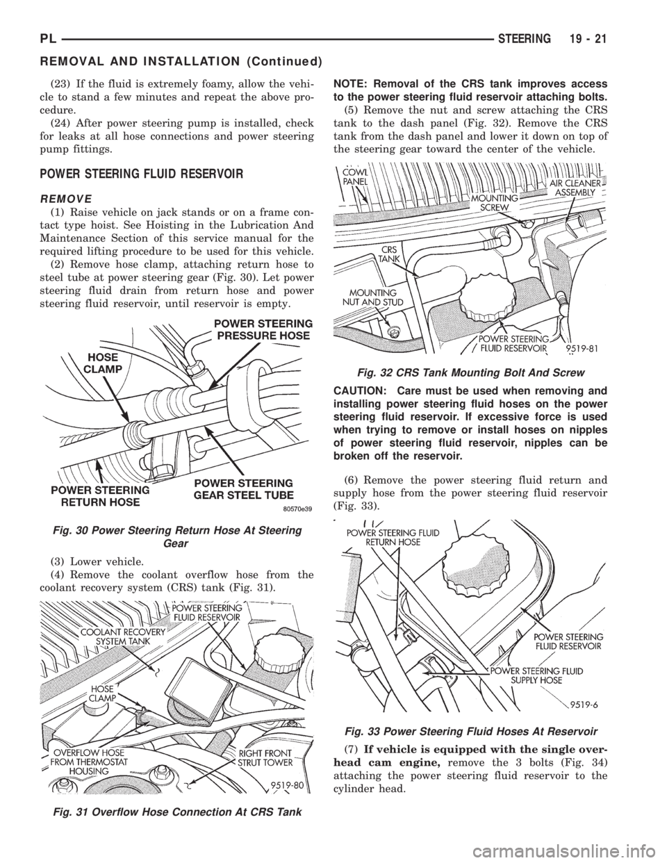
(2) Remove hose clamp, attaching return hose to
steel tube at power steering gear (Fig. 30). Let power
steering fluid drain from return hose and power
steering fluid reservoir, until reservoir is empty.
(3) Lower vehicle.
(4) Remove the coolant overflow hose from the
coolant recovery system (CRS) tank (Fig. 31).NOTE: Removal of the CRS tank improves access
to the power steering fluid reservoir attaching bolts.
(5) Remove the nut and screw attaching the CRS
tank to the dash panel (Fig. 32). Remove the CRS
tank from the dash panel and lower it down on top of
the steering gear toward the center of the vehicle.
CAUTION: Care must be used when removing and
installing power steering fluid hoses on the power
steering fluid reservoir. If excessive force is used
when trying to remove or install hoses on nipples
of power steering fluid reservoir, nipples can be
broken off the reservoir.
(6) Remove the power steering fluid return and
supply hose from the power steering fluid reservoir
(Fig. 33).
(7)If vehicle is equipped with the single over-
head cam engine,remove the 3 bolts (Fig. 34)
attaching the power steering fluid reservoir to the
cylinder head.
Fig. 30 Power Steering Return Hose At Steering
Gear
Fig. 31 Overflow Hose Connection At CRS Tank
Fig. 32 CRS Tank Mounting Bolt And Screw
Fig. 33 Power Steering Fluid Hoses At Reservoir
PLSTEERING 19 - 21
REMOVAL AND INSTALLATION (Continued)
Page 923 of 1200
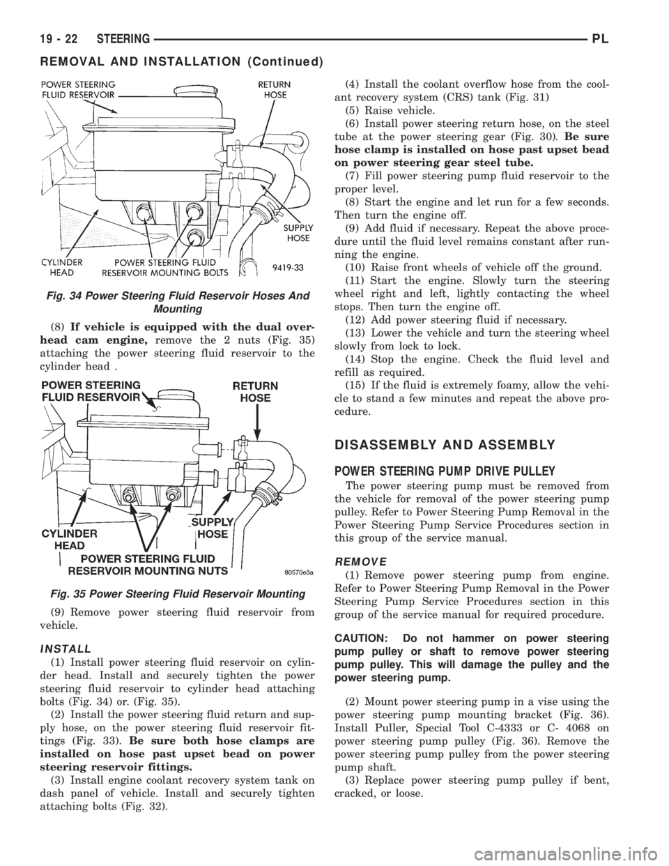
(8)If vehicle is equipped with the dual over-
head cam engine,remove the 2 nuts (Fig. 35)
attaching the power steering fluid reservoir to the
cylinder head .
(9) Remove power steering fluid reservoir from
vehicle.
INSTALL
(1) Install power steering fluid reservoir on cylin-
der head. Install and securely tighten the power
steering fluid reservoir to cylinder head attaching
bolts (Fig. 34) or. (Fig. 35).
(2) Install the power steering fluid return and sup-
ply hose, on the power steering fluid reservoir fit-
tings (Fig. 33).Be sure both hose clamps are
installed on hose past upset bead on power
steering reservoir fittings.
(3) Install engine coolant recovery system tank on
dash panel of vehicle. Install and securely tighten
attaching bolts (Fig. 32).(4) Install the coolant overflow hose from the cool-
ant recovery system (CRS) tank (Fig. 31)
(5) Raise vehicle.
(6) Install power steering return hose, on the steel
tube at the power steering gear (Fig. 30).Be sure
hose clamp is installed on hose past upset bead
on power steering gear steel tube.
(7) Fill power steering pump fluid reservoir to the
proper level.
(8) Start the engine and let run for a few seconds.
Then turn the engine off.
(9) Add fluid if necessary. Repeat the above proce-
dure until the fluid level remains constant after run-
ning the engine.
(10) Raise front wheels of vehicle off the ground.
(11) Start the engine. Slowly turn the steering
wheel right and left, lightly contacting the wheel
stops. Then turn the engine off.
(12) Add power steering fluid if necessary.
(13) Lower the vehicle and turn the steering wheel
slowly from lock to lock.
(14) Stop the engine. Check the fluid level and
refill as required.
(15) If the fluid is extremely foamy, allow the vehi-
cle to stand a few minutes and repeat the above pro-
cedure.
DISASSEMBLY AND ASSEMBLY
POWER STEERING PUMP DRIVE PULLEY
The power steering pump must be removed from
the vehicle for removal of the power steering pump
pulley. Refer to Power Steering Pump Removal in the
Power Steering Pump Service Procedures section in
this group of the service manual.
REMOVE
(1) Remove power steering pump from engine.
Refer to Power Steering Pump Removal in the Power
Steering Pump Service Procedures section in this
group of the service manual for required procedure.
CAUTION: Do not hammer on power steering
pump pulley or shaft to remove power steering
pump pulley. This will damage the pulley and the
power steering pump.
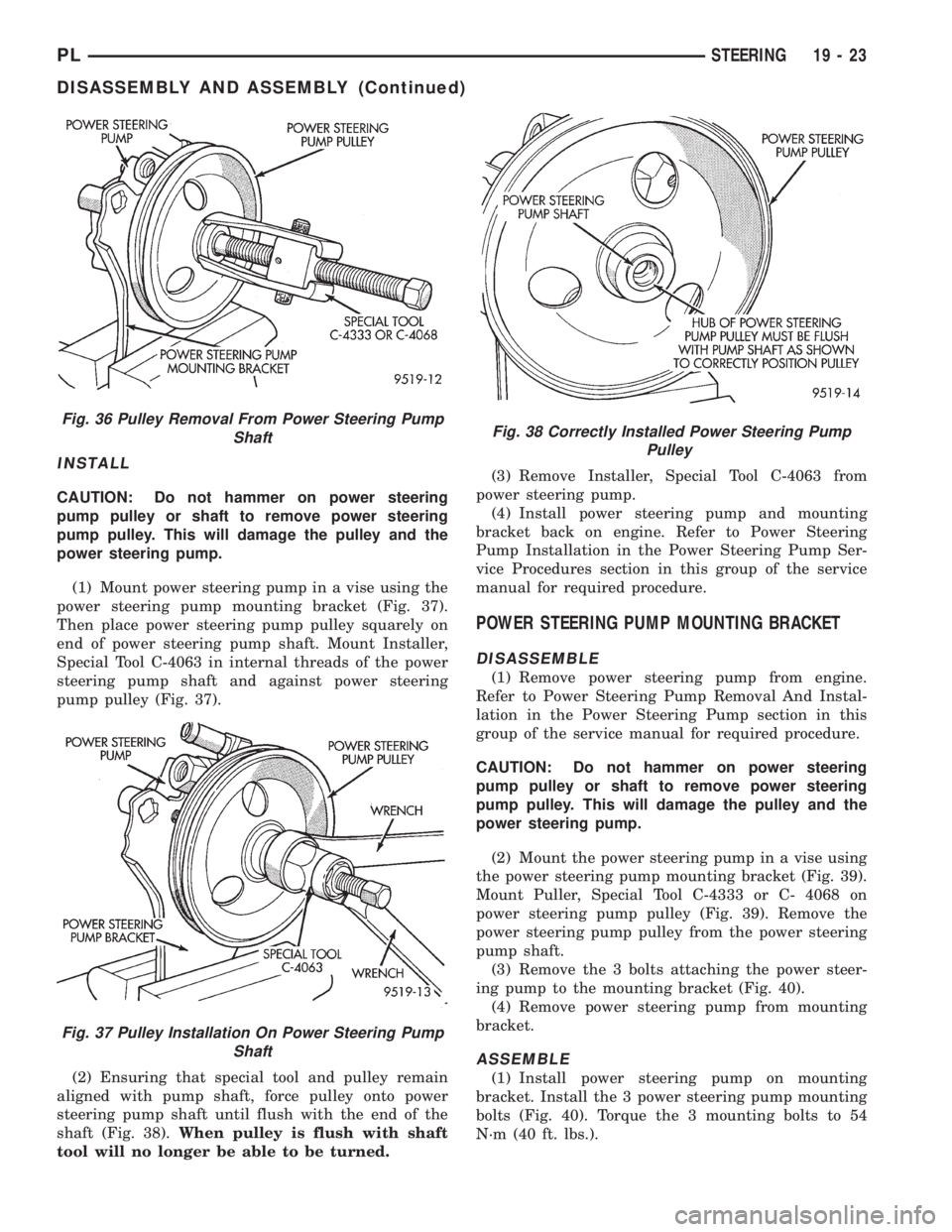
(2) Mount power steering pump in a vise using the
power steering pump mounting bracket (Fig. 36).
Install Puller, Special Tool C-4333 or C- 4068 on
power steering pump pulley (Fig. 36). Remove the
power steering pump pulley from the power steering
pump shaft.
(3) Replace power steering pump pulley if bent,
cracked, or loose.
Fig. 34 Power Steering Fluid Reservoir Hoses And
Mounting
Fig. 35 Power Steering Fluid Reservoir Mounting
19 - 22 STEERINGPL
REMOVAL AND INSTALLATION (Continued)
Page 924 of 1200
INSTALL
CAUTION: Do not hammer on power steering
pump pulley or shaft to remove power steering
pump pulley. This will damage the pulley and the
power steering pump.
(1) Mount power steering pump in a vise using the
power steering pump mounting bracket (Fig. 37).
Then place power steering pump pulley squarely on
end of power steering pump shaft. Mount Installer,
Special Tool C-4063 in internal threads of the power
steering pump shaft and against power steering
pump pulley (Fig. 37).
(2) Ensuring that special tool and pulley remain
aligned with pump shaft, force pulley onto power
steering pump shaft until flush with the end of the
shaft (Fig. 38).When pulley is flush with shaft
tool will no longer be able to be turned.(3) Remove Installer, Special Tool C-4063 from
power steering pump.
(4) Install power steering pump and mounting
bracket back on engine. Refer to Power Steering
Pump Installation in the Power Steering Pump Ser-
vice Procedures section in this group of the service
manual for required procedure.
POWER STEERING PUMP MOUNTING BRACKET
DISASSEMBLE
(1) Remove power steering pump from engine.
Refer to Power Steering Pump Removal And Instal-
lation in the Power Steering Pump section in this
group of the service manual for required procedure.
CAUTION: Do not hammer on power steering
pump pulley or shaft to remove power steering
pump pulley. This will damage the pulley and the
power steering pump.
(2) Mount the power steering pump in a vise using
the power steering pump mounting bracket (Fig. 39).
Mount Puller, Special Tool C-4333 or C- 4068 on
power steering pump pulley (Fig. 39). Remove the
power steering pump pulley from the power steering
pump shaft.
(3) Remove the 3 bolts attaching the power steer-
ing pump to the mounting bracket (Fig. 40).
(4) Remove power steering pump from mounting
bracket.
ASSEMBLE
(1) Install power steering pump on mounting
bracket. Install the 3 power steering pump mounting
bolts (Fig. 40). Torque the 3 mounting bolts to 54
N´m (40 ft. lbs.).
Fig. 36 Pulley Removal From Power Steering Pump
Shaft
Fig. 37 Pulley Installation On Power Steering Pump
Shaft
Fig. 38 Correctly Installed Power Steering Pump
Pulley
PLSTEERING 19 - 23
DISASSEMBLY AND ASSEMBLY (Continued)
Page 925 of 1200
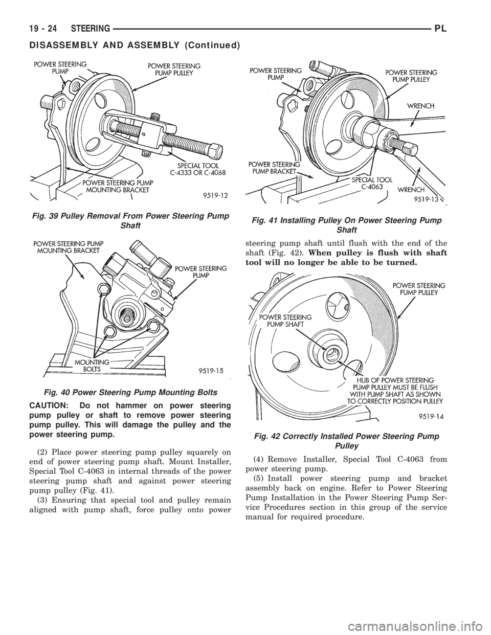
CAUTION: Do not hammer on power steering
pump pulley or shaft to remove power steering
pump pulley. This will damage the pulley and the
power steering pump.
(2) Place power steering pump pulley squarely on
end of power steering pump shaft. Mount Installer,
Special Tool C-4063 in internal threads of the power
steering pump shaft and against power steering
pump pulley (Fig. 41).
(3) Ensuring that special tool and pulley remain
aligned with pump shaft, force pulley onto powersteering pump shaft until flush with the end of the
shaft (Fig. 42).When pulley is flush with shaft
tool will no longer be able to be turned.
(4) Remove Installer, Special Tool C-4063 from
power steering pump.
(5) Install power steering pump and bracket
assembly back on engine. Refer to Power Steering
Pump Installation in the Power Steering Pump Ser-
vice Procedures section in this group of the service
manual for required procedure.
Fig. 41 Installing Pulley On Power Steering Pump
Shaft
Fig. 42 Correctly Installed Power Steering Pump
Pulley
Fig. 39 Pulley Removal From Power Steering Pump
Shaft
Fig. 40 Power Steering Pump Mounting Bolts
19 - 24 STEERINGPL
DISASSEMBLY AND ASSEMBLY (Continued)
Page 926 of 1200
SPECIFICATIONS
POWER STEERING PUMP FLOW SPECIFICATIONS
Power Steering Pump Flow:
At 1500 RPM And
Minimum Pressure.........4.9 to 5.3 Liters/Min
(1.3 to 1.9 GPM)
Control Valve Pressure Relief....8240 to 8920 kPa
(1195 to 1293 psi)
POWER STEERING PUMP FASTENER TORQUE
SPECIFICATIONS
DESCRIPTION TORQUE
Power Steering Hose:
Tube Nuts Pressure And Return...........31N´m
(275 in. lbs.)
Bracket To Front Crossmember
Attaching Bolt.............23N´m(17ft.lbs.).
Power Steering Pump:
Pressure Hose Banjo Bolt......34N´m(25ft.lbs.).
Discharge Fitting.............75N´m(55ft.lbs.)
To Bracket Mounting Bolts.....54N´m(40. ft. lbs.)
Brackets To Engine Mounting Bolts.......54N´m
(40 ft. lbs.)
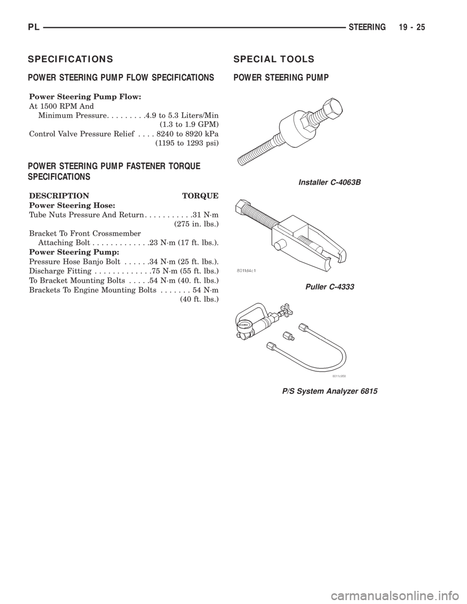
SPECIAL TOOLS
POWER STEERING PUMP
Installer C-4063B
Puller C-4333
P/S System Analyzer 6815
PLSTEERING 19 - 25
Page 927 of 1200
STEERING GEAR
INDEX
page page
DESCRIPTION AND OPERATION
STEERING GEAR........................ 26
DIAGNOSIS AND TESTING
POWER STEERING SYSTEM
TEST PROCEDURE.................... 27
REMOVAL AND INSTALLATION
MANUAL AND POWER STEERING GEAR..... 28DISASSEMBLY AND ASSEMBLY
OUTER TIE ROD........................ 32
SPECIFICATIONS
STEERING GEAR FASTENER
TORQUE SPECIFICATIONS.............. 34
SPECIAL TOOLS
POWER STEERING GEAR................. 34
DESCRIPTION AND OPERATION
STEERING GEAR
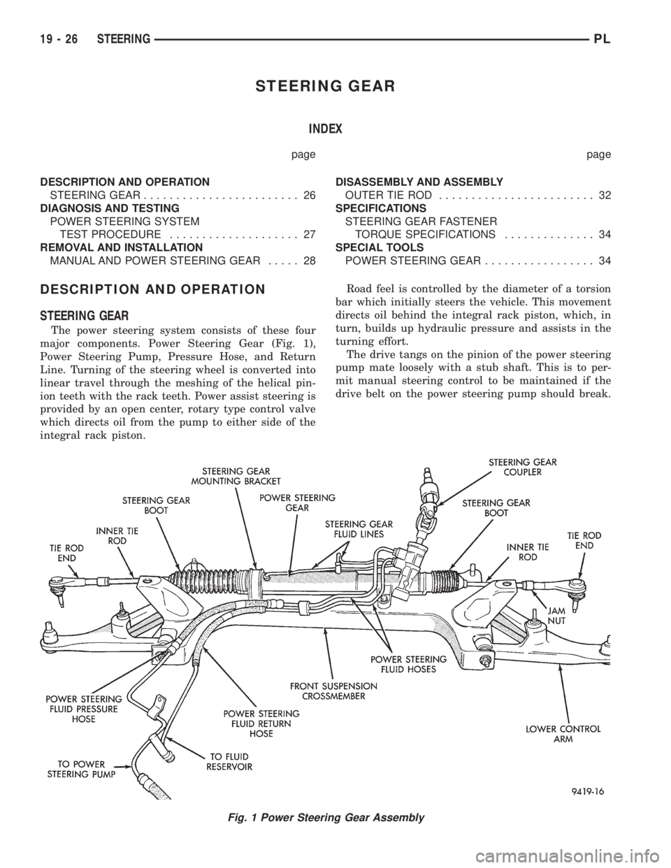
The power steering system consists of these four
major components. Power Steering Gear (Fig. 1),
Power Steering Pump, Pressure Hose, and Return
Line. Turning of the steering wheel is converted into
linear travel through the meshing of the helical pin-
ion teeth with the rack teeth. Power assist steering is
provided by an open center, rotary type control valve
which directs oil from the pump to either side of the
integral rack piston.Road feel is controlled by the diameter of a torsion
bar which initially steers the vehicle. This movement
directs oil behind the integral rack piston, which, in
turn, builds up hydraulic pressure and assists in the
turning effort.
The drive tangs on the pinion of the power steering
pump mate loosely with a stub shaft. This is to per-
mit manual steering control to be maintained if the
drive belt on the power steering pump should break.
Fig. 1 Power Steering Gear Assembly
19 - 26 STEERINGPL
Page 928 of 1200
However, under these conditions, steering effort will
be increased.
NOTE: The power steering gear (Fig. 1) should NOT
be serviced or adjusted. If a malfunction or oil leak
occurs with the steering gear, the complete steering
gear needs to be replaced.
DIAGNOSIS AND TESTING
POWER STEERING SYSTEM TEST PROCEDURE
The following procedure can be used to test the
operation of the power steering system on the vehi-
cle. This test will provide the flow rate of the power
steering pump along with the maximum relief pres-
sure. This test is to be performed any time a power
steering system problem is present to determine if
the power steering pump or power steering gear is
not functioning properly. The following pressure and
flow test is performed using Pressure/Flow Tester,
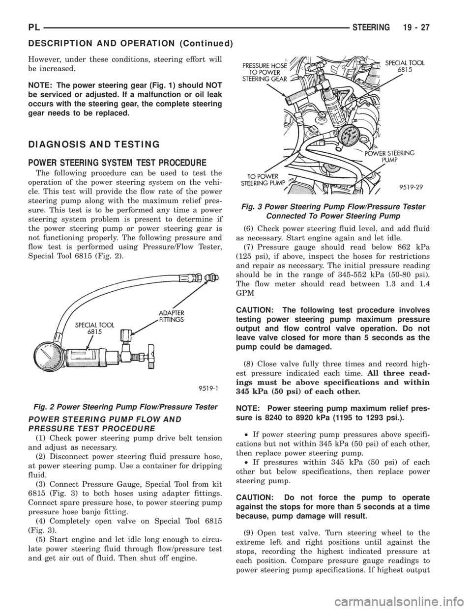
Special Tool 6815 (Fig. 2).
POWER STEERING PUMP FLOW AND
PRESSURE TEST PROCEDURE
(1) Check power steering pump drive belt tension
and adjust as necessary.
(2) Disconnect power steering fluid pressure hose,
at power steering pump. Use a container for dripping
fluid.
(3) Connect Pressure Gauge, Special Tool from kit
6815 (Fig. 3) to both hoses using adapter fittings.
Connect spare pressure hose, to power steering pump
pressure hose banjo fitting.
(4) Completely open valve on Special Tool 6815
(Fig. 3).
(5) Start engine and let idle long enough to circu-
late power steering fluid through flow/pressure test
and get air out of fluid. Then shut off engine.(6) Check power steering fluid level, and add fluid
as necessary. Start engine again and let idle.
(7) Pressure gauge should read below 862 kPa
(125 psi), if above, inspect the hoses for restrictions
and repair as necessary. The initial pressure reading
should be in the range of 345-552 kPa (50-80 psi).
The flow meter should read between 1.3 and 1.4
GPM
CAUTION: The following test procedure involves
testing power steering pump maximum pressure
output and flow control valve operation. Do not
leave valve closed for more than 5 seconds as the
pump could be damaged.
(8) Close valve fully three times and record high-
est pressure indicated each time.All three read-
ings must be above specifications and within
345 kPa (50 psi) of each other.
NOTE: Power steering pump maximum relief pres-
sure is 8240 to 8920 kPa (1195 to 1293 psi.).
²If power steering pump pressures above specifi-
cations but not within 345 kPa (50 psi) of each other,
then replace power steering pump.
²If pressures within 345 kPa (50 psi) of each
other but below specifications, then replace power
steering pump.
CAUTION: Do not force the pump to operate
against the stops for more than 5 seconds at a time
because, pump damage will result.
(9) Open test valve. Turn steering wheel to the
extreme left and right positions until against the
stops, recording the highest indicated pressure at
each position. Compare pressure gauge readings to
power steering pump specifications. If highest output
Fig. 3 Power Steering Pump Flow/Pressure Tester
Connected To Power Steering Pump
Fig. 2 Power Steering Pump Flow/Pressure Tester
PLSTEERING 19 - 27
DESCRIPTION AND OPERATION (Continued)
Page 929 of 1200
pressures are not the same against either stop, the
steering gear is leaking internally and must be
replaced.
REMOVAL AND INSTALLATION
MANUAL AND POWER STEERING GEAR
The removal and replacement procedure for both
the manual and power steering gears is the same.
The only additional steps of the procedure for the
power steering gear, is the removal and replacement
of the power steering fluid lines at the steering gear.
REMOVE
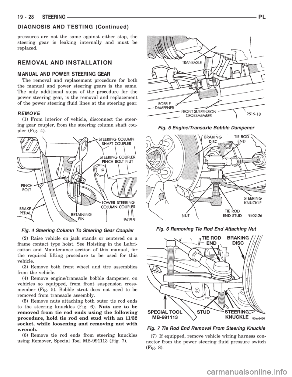
(1) From interior of vehicle, disconnect the steer-
ing gear coupler, from the steering column shaft cou-
pler (Fig. 4).
(2) Raise vehicle on jack stands or centered on a
frame contact type hoist. See Hoisting in the Lubri-
cation and Maintenance section of this manual, for
the required lifting procedure to be used for this
vehicle.
(3) Remove both front wheel and tire assemblies
from the vehicle.
(4) Remove engine/transaxle bobble dampener, on
vehicles so equipped, from front suspension cross-
member (Fig. 5). Bobble strut does not need to be
removed from transaxle assembly.
(5) Remove nuts attaching both outer tie rod ends
to the steering knuckles (Fig. 6).Nuts are to be
removed from tie rod ends using the following
procedure, hold tie rod end stud with an 11/32
socket, while loosening and removing nut with
wrench.
(6) Remove tie rod ends from steering knuckles
using Remover, Special Tool MB-991113 (Fig. 7).(7) If equipped, remove vehicle wiring harness con-
nector from the power steering fluid pressure switch
(Fig. 8).
Fig. 4 Steering Column To Steering Gear Coupler
Fig. 5 Engine/Transaxle Bobble Dampener
Fig. 6 Removing Tie Rod End Attaching Nut
Fig. 7 Tie Rod End Removal From Steering Knuckle
19 - 28 STEERINGPL
DIAGNOSIS AND TESTING (Continued)
Page 930 of 1200
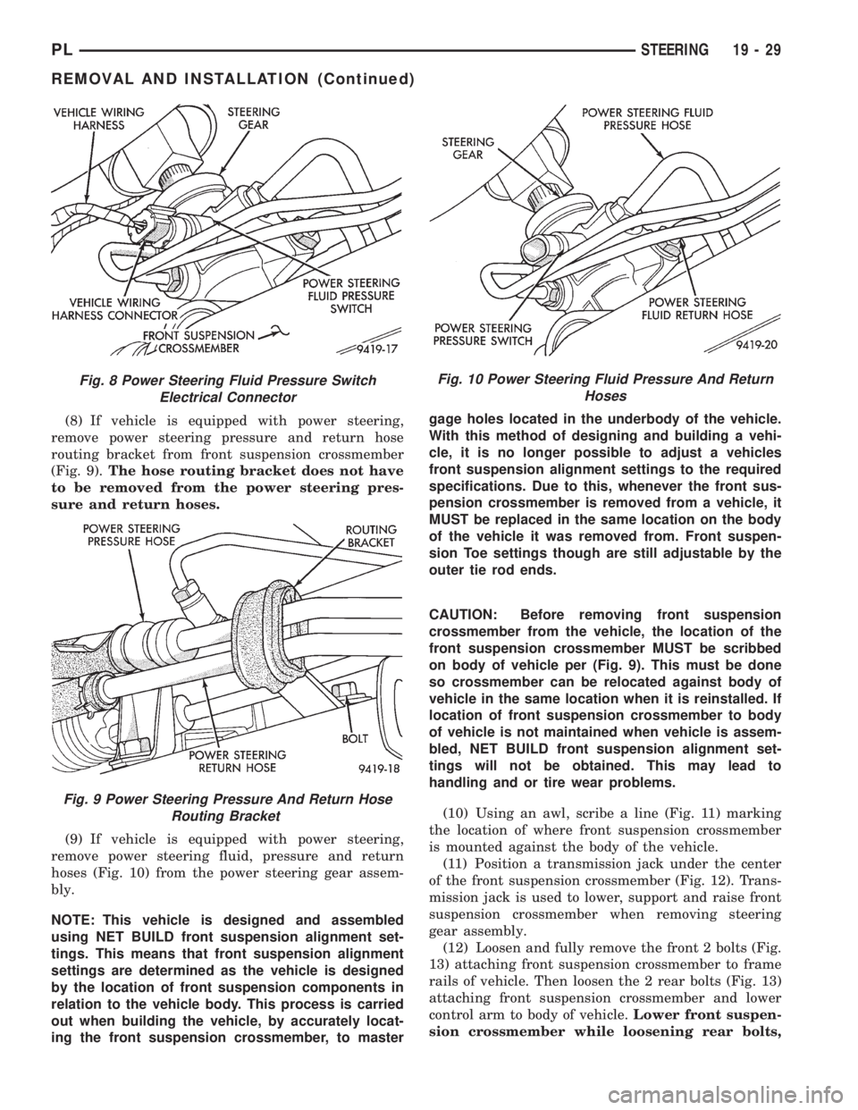
(8) If vehicle is equipped with power steering,
remove power steering pressure and return hose
routing bracket from front suspension crossmember
(Fig. 9).The hose routing bracket does not have
to be removed from the power steering pres-
sure and return hoses.
(9) If vehicle is equipped with power steering,
remove power steering fluid, pressure and return
hoses (Fig. 10) from the power steering gear assem-
bly.
NOTE: This vehicle is designed and assembled
using NET BUILD front suspension alignment set-
tings. This means that front suspension alignment
settings are determined as the vehicle is designed
by the location of front suspension components in
relation to the vehicle body. This process is carried
out when building the vehicle, by accurately locat-
ing the front suspension crossmember, to mastergage holes located in the underbody of the vehicle.
With this method of designing and building a vehi-
cle, it is no longer possible to adjust a vehicles
front suspension alignment settings to the required
specifications. Due to this, whenever the front sus-
pension crossmember is removed from a vehicle, it
MUST be replaced in the same location on the body
of the vehicle it was removed from. Front suspen-
sion Toe settings though are still adjustable by the
outer tie rod ends.
CAUTION: Before removing front suspension
crossmember from the vehicle, the location of the
front suspension crossmember MUST be scribbed
on body of vehicle per (Fig. 9). This must be done
so crossmember can be relocated against body of
vehicle in the same location when it is reinstalled. If
location of front suspension crossmember to body
of vehicle is not maintained when vehicle is assem-
bled, NET BUILD front suspension alignment set-
tings will not be obtained. This may lead to
handling and or tire wear problems.
(10) Using an awl, scribe a line (Fig. 11) marking
the location of where front suspension crossmember
is mounted against the body of the vehicle.
(11) Position a transmission jack under the center
of the front suspension crossmember (Fig. 12). Trans-
mission jack is used to lower, support and raise front
suspension crossmember when removing steering
gear assembly.
(12) Loosen and fully remove the front 2 bolts (Fig.
13) attaching front suspension crossmember to frame
rails of vehicle. Then loosen the 2 rear bolts (Fig. 13)
attaching front suspension crossmember and lower
control arm to body of vehicle.Lower front suspen-
sion crossmember while loosening rear bolts,
Fig. 8 Power Steering Fluid Pressure Switch
Electrical Connector
Fig. 9 Power Steering Pressure And Return Hose
Routing Bracket
Fig. 10 Power Steering Fluid Pressure And Return
Hoses
PLSTEERING 19 - 29
REMOVAL AND INSTALLATION (Continued)