INFINITI QX56 2011 Factory Service Manual
Manufacturer: INFINITI, Model Year: 2011, Model line: QX56, Model: INFINITI QX56 2011Pages: 5598, PDF Size: 94.53 MB
Page 2701 of 5598
SERVICE DATA AND SPECIFICATIONS (SDS)
EM-139
< SERVICE DATA AND SPECIFICATIONS (SDS)
C
D E
F
G H
I
J
K L
M A
EM
NP
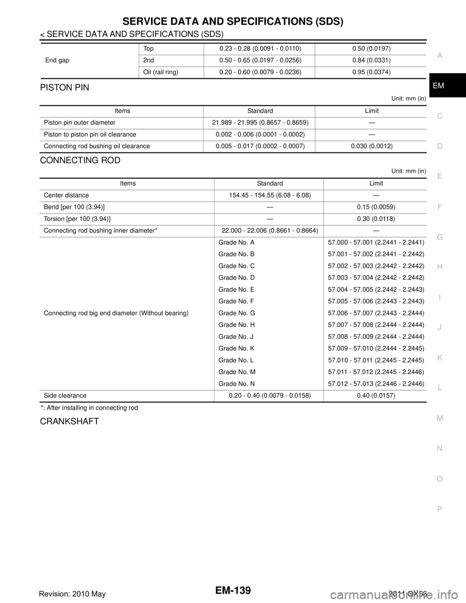
OPISTON PIN
Unit: mm (in)
CONNECTING ROD
Unit: mm (in)
*: After installing in connecting rod
CRANKSHAFT
End gap
Top 0.23 - 0.28 (0.0091 - 0.0110) 0.50 (0.0197)
2nd 0.50 - 0.65 (0.0197 - 0.0256) 0.84 (0.0331)
Oil (rail ring) 0.20 - 0.60 (0.0079 - 0.0236) 0.95 (0.0374)
Items Standard Limit
Piston pin outer diameter 21.989 - 21.995 (0.8657 - 0.8659) —
Piston to piston pin oil clearance 0.002 - 0.006 (0.0001 - 0.0002) —
Connecting rod bushing oil clearance 0.005 - 0.017 (0.0002 - 0.0007) 0.030 (0.0012)
Items Standard Limit
Center distance 154.45 - 154.55 (6.08 - 6.08) —
Bend [per 100 (3.94)] — 0.15 (0.0059)
Torsion [per 100 (3.94)] — 0.30 (0.0118)
Connecting rod bushing inner diameter* 22.000 - 22.006 (0.8661 - 0.8664) —
Connecting rod big end diameter (Without bearing) Grade No. A 57.000 - 57.001 (2.2441 - 2.2441)
Grade No. B 57.001 - 57.002 (2.2441 - 2.2442)
Grade No. C 57.002 - 57.003 (2.2442 - 2.2442)
Grade No. D 57.003 - 57.004 (2.2442 - 2.2442)
Grade No. E 57.004 - 57.005 (2.2442 - 2.2443)
Grade No. F 57.005 - 57.006 (2.2443 - 2.2443)
Grade No. G 57.006 - 57.007 (2.2443 - 2.2444)
Grade No. H 57.007 - 57.008 (2.2444 - 2.2444)
Grade No. J 57.008 - 57.009 (2.2444 - 2.2444)
Grade No. K 57.009 - 57.010 (2.2444 - 2.2445)
Grade No. L 57.010 - 57.011 (2.2445 - 2.2445)
Grade No. M 57.011 - 57.012 (2.2445 - 2.2446)
Grade No. N 57.012 - 57.013 (2.2446 - 2.2446)
Side clearance 0.20 - 0.40 (0.0079 - 0.0158) 0.40 (0.0157)
Revision: 2010 May2011 QX56
Page 2702 of 5598
EM-140
< SERVICE DATA AND SPECIFICATIONS (SDS)
SERVICE DATA AND SPECIFICATIONS (SDS)
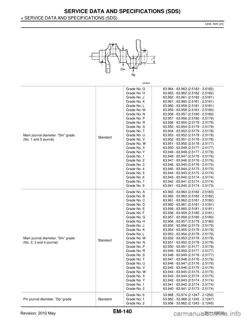
Unit: mm (in)
Main journal diameter. “Dm” grade
(No. 1 and 5 journal)StandardGrade No. G
Grade No. H
Grade No. J
Grade No. K
Grade No. L
Grade No. M
Grade No. N
Grade No. P
Grade No. R
Grade No. S
Grade No. T
Grade No. U
Grade No. V
Grade No. W
Grade No. X
Grade No. Y
Grade No. 1
Grade No. 2
Grade No. 3
Grade No. 4
Grade No. 5
Grade No. 6
Grade No. 7
Grade No. 9 63.964 - 63.963 (2.5183 - 2.5182)
63.963 - 63.962 (2.5182 - 2.5182)
63.962 - 63.961 (2.5182 - 2.5181)
63.961 - 63.960 (2.5181 - 2.5181)
63.960 - 63.959 (2.5181 - 2.5181)
63.959 - 63.958 (2.5181 - 2.5180)
63.958 - 63.957 (2.5180 - 2.5180)
63.957 - 63.956 (2.5180 - 2.5179)
63.956 - 63.955 (2.5179 - 2.5179)
63.955 - 63.954 (2.5179 - 2.5179)
63.954 - 63.953 (2.5179 - 2.5178)
63.953 - 63.952 (2.5178 - 2.5178)
63.952 - 63.951 (2.5178 - 2.5178)
63.951 - 63.950 (2.5178 - 2.5177)
63.950 - 63.949 (2.5177 - 2.5177)
63.949 - 63.948 (2.5177 - 2.5176)
63.948 - 63.947 (2.5176 - 2.5176)
63.947 - 63.946 (2.5176 - 2.5176)
63.946 - 63.945 (2.5176 - 2.5175)
63.945 - 63.944 (2.5175 - 2.5175)
63.944 - 63.943 (2.5175 - 2.5174)
63.943 - 63.942 (2.5174 - 2.5174)
63.942 - 63.941 (2.5174 - 2.5174)
63.941 - 63.940 (2.5174 - 2.5173)
Main journal diameter. “Dm” grade
(No. 2, 3 and 4 journal) StandardGrade No. A
Grade No. B
Grade No. C
Grade No. D
Grade No. E
Grade No. F
Grade No. G
Grade No. H
Grade No. J
Grade No. K
Grade No. L
Grade No. M
Grade No. N
Grade No. P
Grade No. R
Grade No. S
Grade No. T
Grade No. U
Grade No. V
Grade No. W
Grade No. X
Grade No. Y
Grade No. 1
Grade No. 2 63.963 - 63.964 (2.5182 - 2.5183)
63.962 - 63.963 (2.5182 - 2.5182)
63.961 - 63.962 (2.5181 - 2.5182)
63.960 - 63.961 (2.5181 - 2.5181)
63.959 - 63.960 (2.5181 - 2.5181)
63.958 - 63.959 (2.5180 - 2.5181)
63.957 - 63.958 (2.5180 - 2.5180)
63.956 - 63.957 (2.5179 - 2.5180)
63.955 - 63.956 (2.5179 - 2.5179)
63.954 - 63.955 (2.5179 - 2.5179)
63.953 - 63.954 (2.5178 - 2.5179)
63.952 - 63.953 (2.5178 - 2.5178)
63.951 - 63.952 (2.5178 - 2.5178)
63.950 - 63.951 (2.5177 - 2.5178)
63.949 - 63.950 (2.5177 - 2.5177)
63.948 - 63.949 (2.5176 - 2.5177)
63.947 - 63.948 (2.5176 - 2.5176)
63.946 - 63.947 (2.5176 - 2.5176)
63.945 - 63.946 (2.5175 - 2.5176)
63.944 - 63.945 (2.5175 - 2.5175)
63.943 - 63.944 (2.5174 - 2.5175)
63.942 - 63.943 (2.5174 - 2.5174)
63.941 - 63.942 (2.5174 - 2.5174)
63.940 - 63.941 (2.5173 - 2.5174)
Pin journal diameter. “Dp” grade Standard Grade No. 0
Grade No. 1
Grade No. 253.968 - 53.974 (2.1247 - 2.1250)
53.962 - 53.968 (2.1245 - 2.1247)
53.956 - 53.962 (2.1243 - 2.1245)
SEM645
Revision: 2010 May2011 QX56
Page 2703 of 5598
SERVICE DATA AND SPECIFICATIONS (SDS)
EM-141
< SERVICE DATA AND SPECIFICATIONS (SDS)
C
D E
F
G H
I
J
K L
M A
EM
NP
O
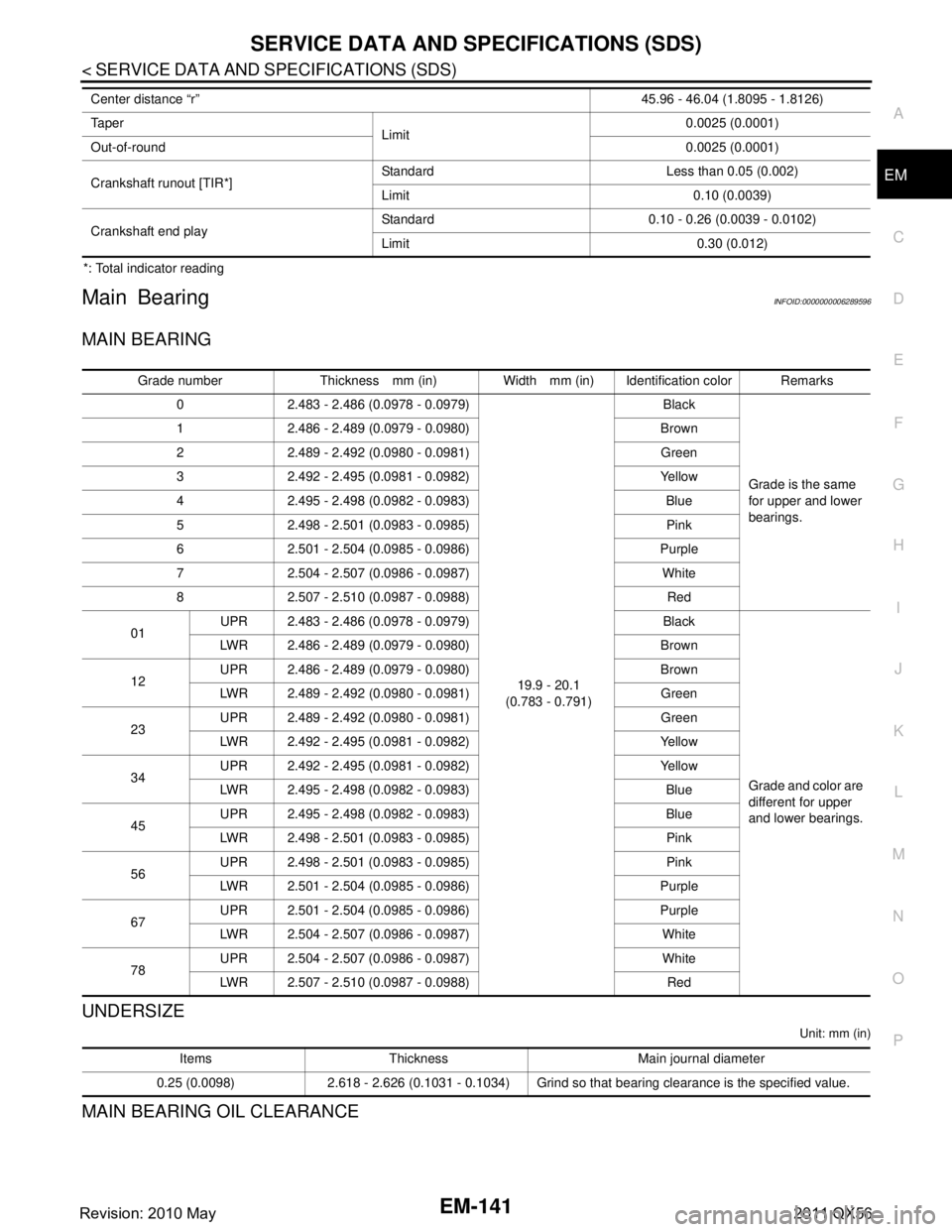
*: Total indicator reading
Main BearingINFOID:0000000006289596
MAIN BEARING
UNDERSIZE
Unit: mm (in)
MAIN BEARING OIL CLEARANCE
Center distance “r”
45.96 - 46.04 (1.8095 - 1.8126)
Ta p e r Limit 0.0025 (0.0001)
Out-of-round 0.0025 (0.0001)
Crankshaft runout [TIR*] Standard Less than 0.05 (0.002)
Limit 0.10 (0.0039)
Crankshaft end play Standard 0.10 - 0.26 (0.0039 - 0.0102)
Limit 0.30 (0.012)
Grade number Thickness mm (in) Width mm (in) Identification color Remarks
0 2.483 - 2.486 (0.0978 - 0.0979)
19.9 - 20.1
(0.783 - 0.791) Black
Grade is the same
for upper and lower
bearings.
1 2.486 - 2.489 (0.0979 - 0.0980) Brown
2 2.489 - 2.492 (0.0980 - 0.0981) Green
3 2.492 - 2.495 (0.0981 - 0.0982) Yellow
4 2.495 - 2.498 (0.0982 - 0.0983) Blue
5 2.498 - 2.501 (0.0983 - 0.0985) Pink
6 2.501 - 2.504 (0.0985 - 0.0986) Purple
7 2.504 - 2.507 (0.0986 - 0.0987) White
8 2.507 - 2.510 (0.0987 - 0.0988) Red
01 UPR 2.483 - 2.486 (0.0978 - 0.0979) Black
Grade and color are
different for upper
and lower bearings.
LWR 2.486 - 2.489 (0.0979 - 0.0980) Brown
12 UPR 2.486 - 2.489 (0.0979 - 0.0980) Brown
LWR 2.489 - 2.492 (0.0980 - 0.0981) Green
23 UPR 2.489 - 2.492 (0.0980 - 0.0981) Green
LWR 2.492 - 2.495 (0.0981 - 0.0982) Yellow
34 UPR 2.492 - 2.495 (0.0981 - 0.0982) Yellow
LWR 2.495 - 2.498 (0.0982 - 0.0983) Blue
45 UPR 2.495 - 2.498 (0.0982 - 0.0983) Blue
LWR 2.498 - 2.501 (0.0983 - 0.0985) Pink
56 UPR 2.498 - 2.501 (0.0983 - 0.0985) Pink
LWR 2.501 - 2.504 (0.0985 - 0.0986) Purple
67 UPR 2.501 - 2.504 (0.0985 - 0.0986) Purple
LWR 2.504 - 2.507 (0.0986 - 0.0987) White
78 UPR 2.504 - 2.507 (0.0986 - 0.0987) White
LWR 2.507 - 2.510 (0.0987 - 0.0988) Red
Items Thickness Main journal diameter
0.25 (0.0098) 2.618 - 2.626 (0.1031 - 0.1034) Grind so that bearing clearance is the specified value.
Revision: 2010 May2011 QX56
Page 2704 of 5598

EM-142
< SERVICE DATA AND SPECIFICATIONS (SDS)
SERVICE DATA AND SPECIFICATIONS (SDS)
Unit: mm (in)
*: Actual clearance
Connecting Rod BearingINFOID:0000000006289597
CONNECTING ROD BEARING
UNDERSIZE
Unit: mm (in)
CONNECTING ROD BEARING OIL CLEARANCE
Unit: mm (in)
*: Actual clearanceItems Standard Limit
Main bearing oil clearance No.1 and 5 0.001 - 0.011 (0.00004 - 0.00043)*
0.065 (0.0026)
No.2, 3 and 4 0.007 - 0.017 (0.0003 - 0.0007)*
Grade number Thickness mm (in) Width mm (in) Identification color (mark)
1 1.500 - 1.503 (0.0591 - 0.0592)
18.1 - 18.3
(0.713 - 0.720) Black
2 1.503 - 1.506 (0.0592 - 0.0593) Brown
3 1.506 - 1.509 (0.0593 - 0.0594) Green
4 1.509 - 1.512 (0.0594 - 0.0595) Yellow
Items Thickness Pin journal diameter
0.25 (0.0098) 1.627 - 1.635 (0.0641 - 0.0644) Grind so that bearing clearance is the specified value.
Items Standard Limit
Connecting rod bearing oil clearance 0.020 - 0.039 (0.0008 - 0.0015)* 0.070 (0.0028)
Revision: 2010 May2011 QX56
Page 2705 of 5598
EX-1
ENGINE
C
DE
F
G H
I
J
K L
M
SECTION EX
A
EX
N
O P
CONTENTS
EXHAUST SYSTEM
PRECAUTION ................ ...............................2
PRECAUTIONS .............................................. .....2
Removal and Installation ..................................... ......2
PREPARATION ............................................3
PREPARATION .............................................. .....3
Special Service Tool ........................................... ......3
Commercial Service Tool ..........................................3
PERIODIC MAINTENANCE .........................4
EXHAUST SYSTEM ...........................................4
Inspection ............................................................ .....4
REMOVAL AND INSTALLATION ................5
EXHAUST SYSTEM ...........................................5
Exploded View ..................................................... .....5
Removal and Installation ..........................................5
Inspection .................................................................6
Revision: 2010 May2011 QX56
Page 2706 of 5598
EX-2
< PRECAUTION >
PRECAUTIONS
PRECAUTION
PRECAUTIONS
Removal and InstallationINFOID:0000000006289691
CAUTION:
• Be sure to use genuine exhaust system parts or equivalents which are specially designed for heat
resistance, corrosion resistance, and shape.
Perform the operation with the exhaust system fully cooled down because the system will be hot
just after engine stops.
Be careful not to cut your hand on the heat insulator edge.
Revision: 2010 May2011 QX56
Page 2707 of 5598
PREPARATIONEX-3
< PREPARATION >
C
DE
F
G H
I
J
K L
M A
EX
NP
O
PREPARATION
PREPARATION
Special Service ToolINFOID:0000000006289692
Commercial Service ToolINFOID:0000000006289693
Tool number
(Kent-Moore No.)
Tool name
Description
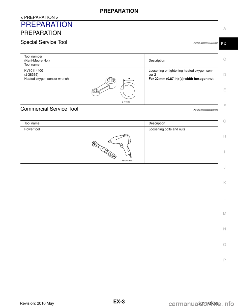
KV10114400
(J-38365)
Heated oxygen sensor wrench Loosening or tightening heated oxygen sen-
sor 2
For 22 mm (0.87 in) (a) width hexagon nut
S-NT636
Tool name
Description
Power tool Loosening bolts and nuts
PBIC0190E
Revision: 2010 May2011 QX56
Page 2708 of 5598
EX-4
< PERIODIC MAINTENANCE >
EXHAUST SYSTEM
PERIODIC MAINTENANCE
EXHAUST SYSTEM
InspectionINFOID:0000000006289694
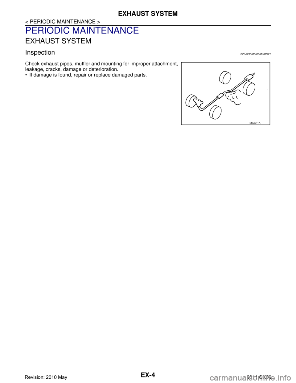
Check exhaust pipes, muffler and mounting for improper attachment,
leakage, cracks, damage or deterioration.
• If damage is found, repair or replace damaged parts.
SMA211A
Revision: 2010 May2011 QX56
Page 2709 of 5598
EXHAUST SYSTEMEX-5
< REMOVAL AND INSTALLATION >
C
DE
F
G H
I
J
K L
M A
EX
NP
O
REMOVAL AND INSTALLATION
EXHAUST SYSTEM
Exploded ViewINFOID:0000000006289695
Removal and InstallationINFOID:0000000006289696
REMOVAL
Disconnect each joint and mounting using power tool.
Remove heated oxygen sens
or 2, as follows:.
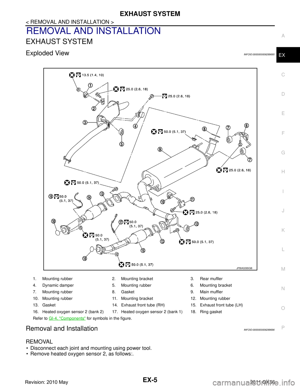
1. Mounting rubber 2. Mounting bracket 3. Rear mufller
4. Dynamic damper 5. Mounting rubber 6. Mounting bracket
7. Mounting rubber 8. Gasket 9. Main muffler
10. Mounting rubber 11. Mounting bracket 12. Mounting rubber
13. Gasket 14. Exhaust front tube (RH) 15. Exhaust front tube (LH)
16. Heated oxygen sensor 2 (bank 2) 17. Heated oxygen sensor 2 (bank 1) 18. Ring gasket
Refer to GI-4, "
Components" for symbols in the figure.
JPBIA3265GB
Revision: 2010 May2011 QX56
Page 2710 of 5598
![INFINITI QX56 2011 Factory Service Manual
EX-6
< REMOVAL AND INSTALLATION >
EXHAUST SYSTEM
- Using heated oxygen sensor wrench [SST: KV10114400] (C),removal heated oxygen sensor 2.
INSTALLATION
Note the following items, and install in the re INFINITI QX56 2011 Factory Service Manual
EX-6
< REMOVAL AND INSTALLATION >
EXHAUST SYSTEM
- Using heated oxygen sensor wrench [SST: KV10114400] (C),removal heated oxygen sensor 2.
INSTALLATION
Note the following items, and install in the re](/img/42/57033/w960_57033-2709.png)
EX-6
< REMOVAL AND INSTALLATION >
EXHAUST SYSTEM
- Using heated oxygen sensor wrench [SST: KV10114400] (C),removal heated oxygen sensor 2.
INSTALLATION
Note the following items, and install in the reverse order of removal.
Temporarily tighten bolts and nuts when installing exhaust pipe assembly. Tighten them to the specifiedtorque when connecting the vehicle rear to the vehicle front.
CAUTION:
Always replace exhaust tube gasket s with new ones when reassembling.
If heat insulator is badly deformed, repair or re place it. If deposits such as mud pile up on the heat
insulator, remove them.
When installing heat insulator avoid large gaps or interference between heat insulator and each
exhaust pipe.
Remove deposits from the sealing surface of each connection. Connect them securely to avoid
gases leakage.
Check each part for unusual interference, and then tighten them to the specified torque.
When installing each moun ting rubber, avoid twisting or unusua l extension in up/down and right/left
directions.
InspectionINFOID:0000000006289697
INSPECTION AFTER INSTALLATION
Check clearance between tail tube and rear bumper is even.
With engine running, check exhaust tube joints for gas leakage and unusual noises.
Check to ensure that mounting brackets and mounting rubbers are installed properly and free from undue stress. Improper installation could result in excessive noise and vibration.
A: Bank 1
B: Bank 2
: Vehicle front
JPBIA3395ZZ
Revision: 2010 May2011 QX56