INFINITI QX56 2011 Factory Service Manual
Manufacturer: INFINITI, Model Year: 2011, Model line: QX56, Model: INFINITI QX56 2011Pages: 5598, PDF Size: 94.53 MB
Page 3821 of 5598
MWI-78
< SYMPTOM DIAGNOSIS >
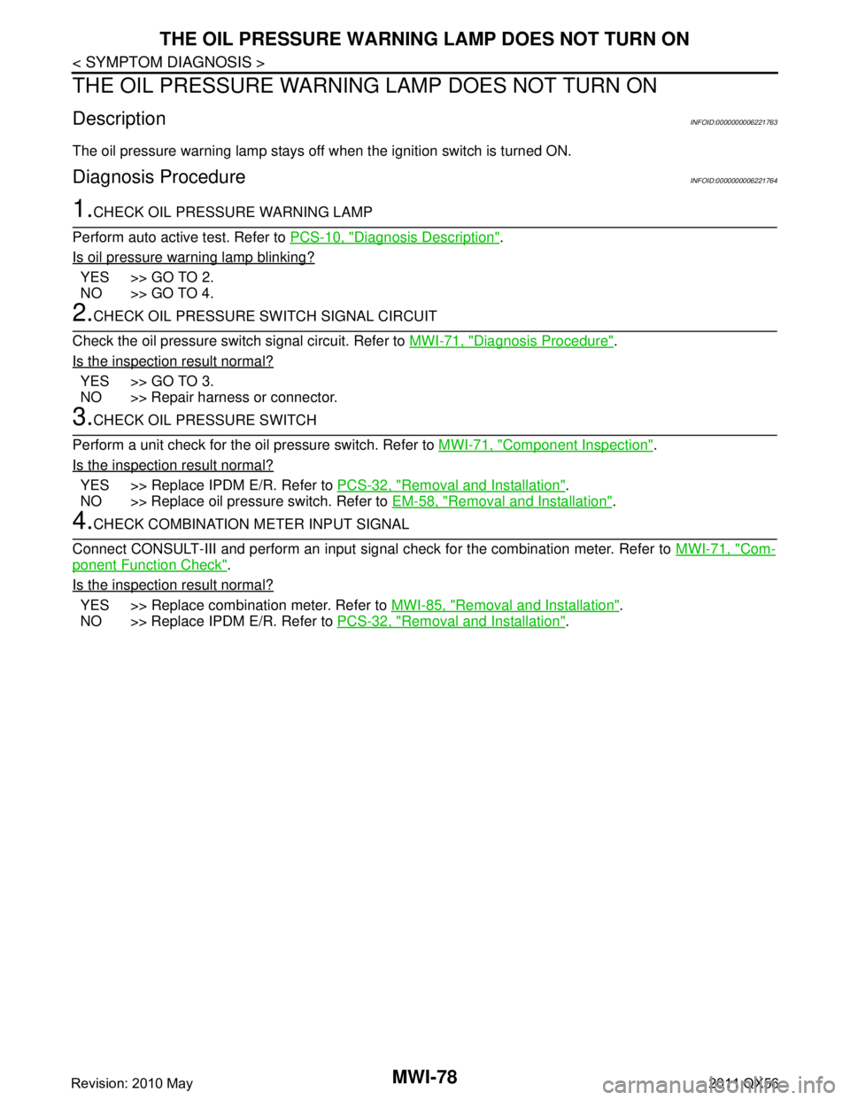
THE OIL PRESSURE WARNING LAMP DOES NOT TURN ON
THE OIL PRESSURE WARNING LAMP DOES NOT TURN ON
DescriptionINFOID:0000000006221763
The oil pressure warning lamp stays off when the ignition switch is turned ON.
Diagnosis ProcedureINFOID:0000000006221764
1.CHECK OIL PRESSURE WARNING LAMP
Perform auto active test. Refer to PCS-10, "
Diagnosis Description".
Is oil pressure warning lamp blinking?
YES >> GO TO 2.
NO >> GO TO 4.
2.CHECK OIL PRESSURE SWITCH SIGNAL CIRCUIT
Check the oil pressure switch signal circuit. Refer to MWI-71, "
Diagnosis Procedure".
Is the inspection result normal?
YES >> GO TO 3.
NO >> Repair harness or connector.
3.CHECK OIL PRESSURE SWITCH
Perform a unit check for the oil pressure switch. Refer to MWI-71, "
Component Inspection".
Is the inspection result normal?
YES >> Replace IPDM E/R. Refer to PCS-32, "Removal and Installation".
NO >> Replace oil pressure switch. Refer to EM-58, "
Removal and Installation".
4.CHECK COMBINATION METER INPUT SIGNAL
Connect CONSULT-III and perform an input signal check for the combination meter. Refer to MWI-71, "
Com-
ponent Function Check".
Is the inspection result normal?
YES >> Replace combination meter. Refer to MWI-85, "Removal and Installation".
NO >> Replace IPDM E/R. Refer to PCS-32, "
Removal and Installation".
Revision: 2010 May2011 QX56
Page 3822 of 5598
MWI
THE OIL PRESSURE WARNING LAMP DOES NOT TURN OFFMWI-79
< SYMPTOM DIAGNOSIS >
C
DE
F
G H
I
J
K L
M B A
O P
THE OIL PRESSURE WARNING LAMP DOES NOT TURN OFF
DescriptionINFOID:0000000006221765
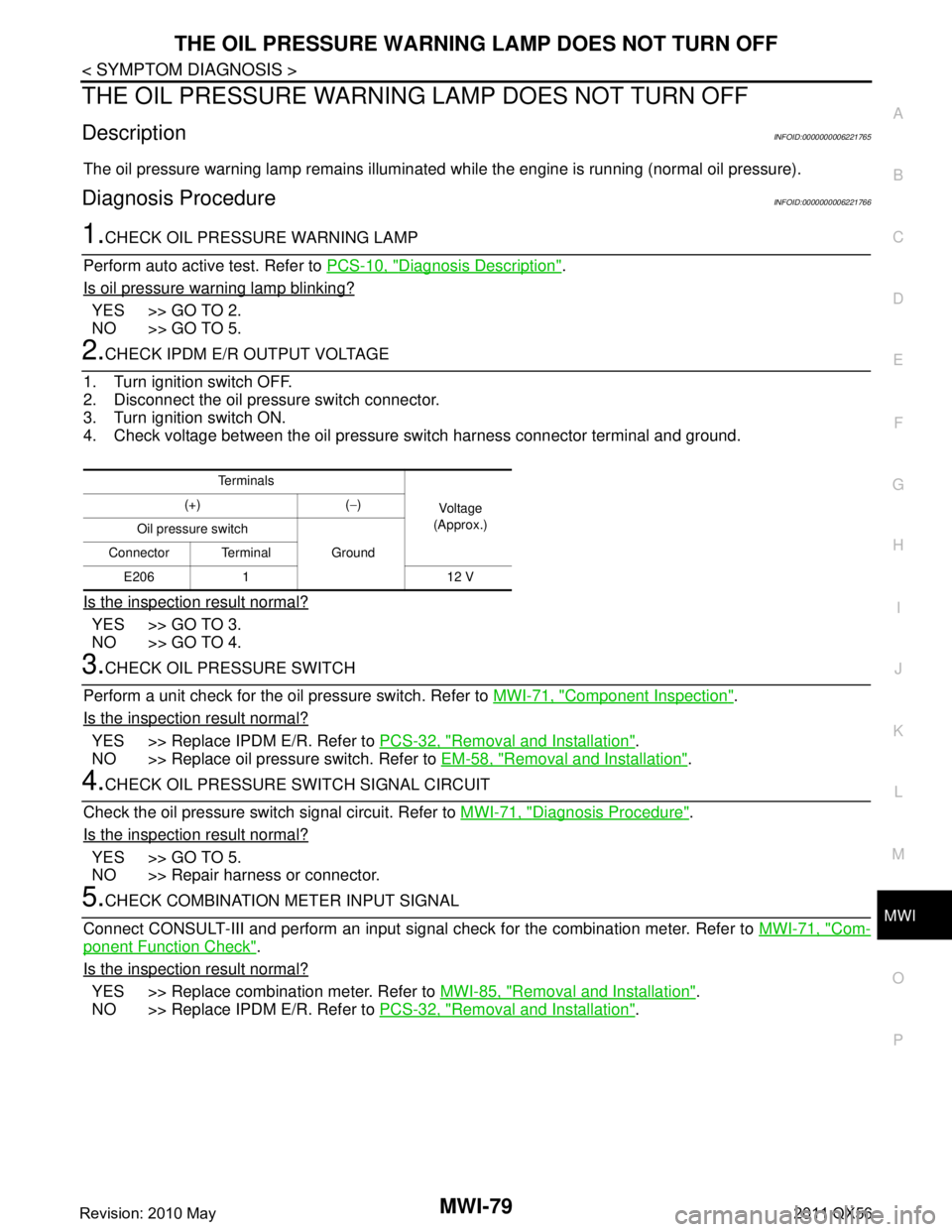
The oil pressure warning lamp remains illuminated while the engine is running (normal oil pressure).
Diagnosis ProcedureINFOID:0000000006221766
1.CHECK OIL PRESSURE WARNING LAMP
Perform auto active test. Refer to PCS-10, "
Diagnosis Description".
Is oil pressure warning lamp blinking?
YES >> GO TO 2.
NO >> GO TO 5.
2.CHECK IPDM E/R OUTPUT VOLTAGE
1. Turn ignition switch OFF.
2. Disconnect the oil pressure switch connector.
3. Turn ignition switch ON.
4. Check voltage between the oil pressure switch harness connector terminal and ground.
Is the inspection result normal?
YES >> GO TO 3.
NO >> GO TO 4.
3.CHECK OIL PRESSURE SWITCH
Perform a unit check for the oil pressure switch. Refer to MWI-71, "
Component Inspection".
Is the inspection result normal?
YES >> Replace IPDM E/R. Refer to PCS-32, "Removal and Installation".
NO >> Replace oil pressure switch. Refer to EM-58, "
Removal and Installation".
4.CHECK OIL PRESSURE SWITCH SIGNAL CIRCUIT
Check the oil pressure switch signal circuit. Refer to MWI-71, "
Diagnosis Procedure".
Is the inspection result normal?
YES >> GO TO 5.
NO >> Repair harness or connector.
5.CHECK COMBINATION METER INPUT SIGNAL
Connect CONSULT-III and perform an input signal check for the combination meter. Refer to MWI-71, "
Com-
ponent Function Check".
Is the inspection result normal?
YES >> Replace combination meter. Refer to MWI-85, "Removal and Installation".
NO >> Replace IPDM E/R. Refer to PCS-32, "
Removal and Installation".
Te r m i n a l s
Voltag e
(Approx.)
(+) (
−)
Oil pressure switch Ground
Connector Terminal
E206 1 12 V
Revision: 2010 May2011 QX56
Page 3823 of 5598

MWI-80
< SYMPTOM DIAGNOSIS >
THE PARKING BRAKE RELEASE WARNING CONTINUES DISPLAYING, OR
DOES NOT DISPLAY
THE PARKING BRAKE RELEASE WA RNING CONTINUES DISPLAYING,
OR DOES NOT DISPLAY
DescriptionINFOID:0000000006221767
The parking brake warning is displayed during vehi cle travel even though the parking brake is released.
The parking brake warning is not displayed even though driving the vehicle with the parking brake applied.
Diagnosis ProcedureINFOID:0000000006221768
1.CHECK PARKING BRAKE WARNING LAMP OPERATION
1. Start engine.
2. Check the operation of the brake warni ng lamp when operating the parking brake.
Is the inspection result normal?
YES >> Replace combination meter. Refer to MWI-85, "Removal and Installation".
NO >> GO TO 2.
2.CHECK PARKING BRAKE SWITCH SIGNAL CIRCUIT
1. Turn ignition switch OFF.
2. Check the parking brake switch signal circuit. Refer to WCS-43, "
Diagnosis Procedure".
Is the inspection result normal?
YES >> GO TO 3.
NO >> Repair harness or connector.
3.CHECK PARKING BRAKE SWITCH UNIT
Perform a unit check for the parking brake switch. Refer to BRC-118, "
Component Inspection".
Is the inspection result normal?
YES >> Replace combination meter. Refer to MWI-85, "Removal and Installation".
NO >> Replace parking brake switch. Refer to PB-5, "
Exploded View".
Condition Warning lamp status
Parking brake applied ON
Parking brake released OFF
Revision: 2010 May2011 QX56
Page 3824 of 5598
MWI
THE LOW WASHER FLUID WARNING CONTINUES DISPLAYING, OR DOES
NOT DISPLAY
MWI-81
< SYMPTOM DIAGNOSIS >
C
DE
F
G H
I
J
K L
M B A
O P
THE LOW WASHER FLUID WARNING CONTINUES DISPLAYING, OR
DOES NOT DISPLAY
DescriptionINFOID:0000000006221769
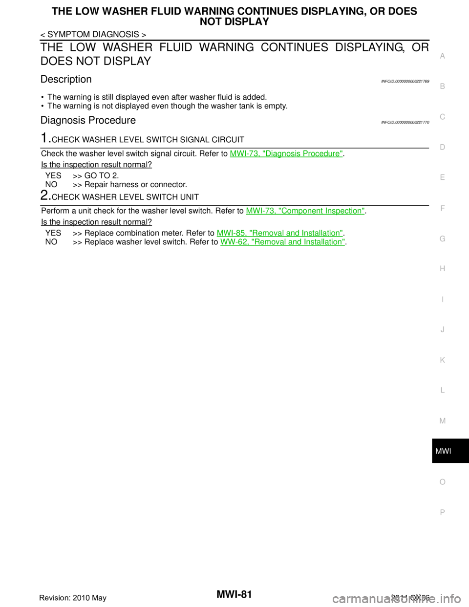
The warning is still displayed even after washer fluid is added.
The warning is not displayed even though the washer tank is empty.
Diagnosis ProcedureINFOID:0000000006221770
1.CHECK WASHER LEVEL SWITCH SIGNAL CIRCUIT
Check the washer level switch signal circuit. Refer to MWI-73, "
Diagnosis Procedure".
Is the inspection result normal?
YES >> GO TO 2.
NO >> Repair harness or connector.
2.CHECK WASHER LEVEL SWITCH UNIT
Perform a unit check for the washer level switch. Refer to MWI-73, "
Component Inspection".
Is the inspection result normal?
YES >> Replace combination meter. Refer to MWI-85, "Removal and Installation".
NO >> Replace washer level switch. Refer to WW-62, "
Removal and Installation".
Revision: 2010 May2011 QX56
Page 3825 of 5598

MWI-82
< SYMPTOM DIAGNOSIS >
THE DOOR OPEN WARNING CONTINUES DISPLAYING, OR DOES NOT DIS-
PLAY
THE DOOR OPEN WARNING CONTIN UES DISPLAYING, OR DOES NOT
DISPLAY
DescriptionINFOID:0000000006221771
The door open warning is displayed even though all of the doors are closed.
The door open warning is not displayed even though a door is ajar.
Diagnosis ProcedureINFOID:0000000006221772
1.CHECK BCM INPUT/OUTPUT SIGNAL
Connect CONSULT-III and check the BCM input signals. Refer to DLK-117, "
ComponentFunctionCheck".
Is the inspection result normal?
YES >> GO TO 2.
NO >> GO TO 3.
2.CHECK COMBINATION METER INPUT SIGNAL
Select the “Data Monitor” for the “METER/M&A” and check the “DOOR W/L” monitor value.
Is the inspection result normal?
YES >> Replace combination meter. Refer to MWI-85, "Removal and Installation".
NO >> Replace BCM. Refer to BCS-81, "
Removal and Installation".
3.CHECK DOOR SWITCH SIGNAL CIRCUIT
Check the door switch signal circuit. Refer to DLK-117, "
Diagnosis Procedure".
Is the inspection result normal?
YES >> GO TO 4.
NO >> Repair harness or connector.
4.CHECK DOOR SWITCH
Perform a unit check for the door switch. Refer to DLK-119, "
Component Inspection".
Is the inspection result normal?
YES >> Replace combination meter. Refer to MWI-85, "Removal and Installation".
NO >> Replace applicable door switch. Refer to DLK-254, "
Removal and Installation".
“DOOR W/L”
Door open : On
Door closed : Off
Revision: 2010 May2011 QX56
Page 3826 of 5598

MWI
THE AMBIENT TEMPERATURE DISPLAY IS INCORRECT
MWI-83
< SYMPTOM DIAGNOSIS >
C
D E
F
G H
I
J
K L
M B A
O P
THE AMBIENT TEMPERATURE DISPLAY IS INCORRECT
DescriptionINFOID:0000000006221773
The displayed ambient air temperature is higher than the actual temperature.
The displayed ambient air temperature is lower than the actual temperature.
Diagnosis ProcedureINFOID:0000000006221774
NOTE:
Check that the symptom is not applicable to the no rmal operating condition before starting diagnosis. Refer to
MWI-84, "
INFORMATION DISPLAY : Description".
1.CHECK AMBIENT SENSOR SIGNAL CIRCUIT
Check the ambient sensor signal circuit. Refer to HAC-77, "
Diagnosis Procedure".
Is the inspection result normal?
YES >> GO TO 2.
NO >> Repair harness or connector.
2.CHECK A/C AUTO AMP. CONNECTION RECOGNITION SIGNAL CIRCUIT
Check the A/C auto amp. connection re cognition signal circuit. Refer to MWI-74, "
DiagnosisProcedure".
Is the inspection result normal?
YES >> GO TO 3.
NO >> Repair harness or connector.
3.CHECK AMBIENT SENSOR
Perform the part check for t he ambient sensor. Refer to HAC-78, "
Component Inspection".
Is the inspection result normal?
YES >> Replace combination meter. Refer to MWI-85, "Removal and Installation".
NO >> Replace ambient sensor. Refer to HAC-147, "
Removal and Installation".
Revision: 2010 May2011 QX56
Page 3827 of 5598

MWI-84
< SYMPTOM DIAGNOSIS >
NORMAL OPERATING CONDITION
NORMAL OPERATING CONDITION
INFORMATION DISPLAY
INFORMATION DISPLAY : DescriptionINFOID:0000000006221775
AMBIENT AIR TEMPERATURE
The displayed ambient air temperature on the information display may differ from the actual temperature
because it is a corrected value calculated from the ambi ent sensor signal by the combination meter. Refer to
MWI-20, "
INFORMATION DISPLAY : System Description" for details on the correction process.
DISTANCE TO EMPTY
The calculated distance to empty may differ from the actual distance to empty if the refueling amount is
approximately 15 (4 US gal, 3-1/4 Imp gal) or less. Th is is because the refuel control (moves the fuel gauge
needle quicker than normal judging that the driver is refueling the vehicle) is not performing.
Revision: 2010 May2011 QX56
Page 3828 of 5598
MWI
COMBINATION METERMWI-85
< REMOVAL AND INSTALLATION >
C
DE
F
G H
I
J
K L
M B A
O P
REMOVAL AND INSTALLATION
COMBINATION METER
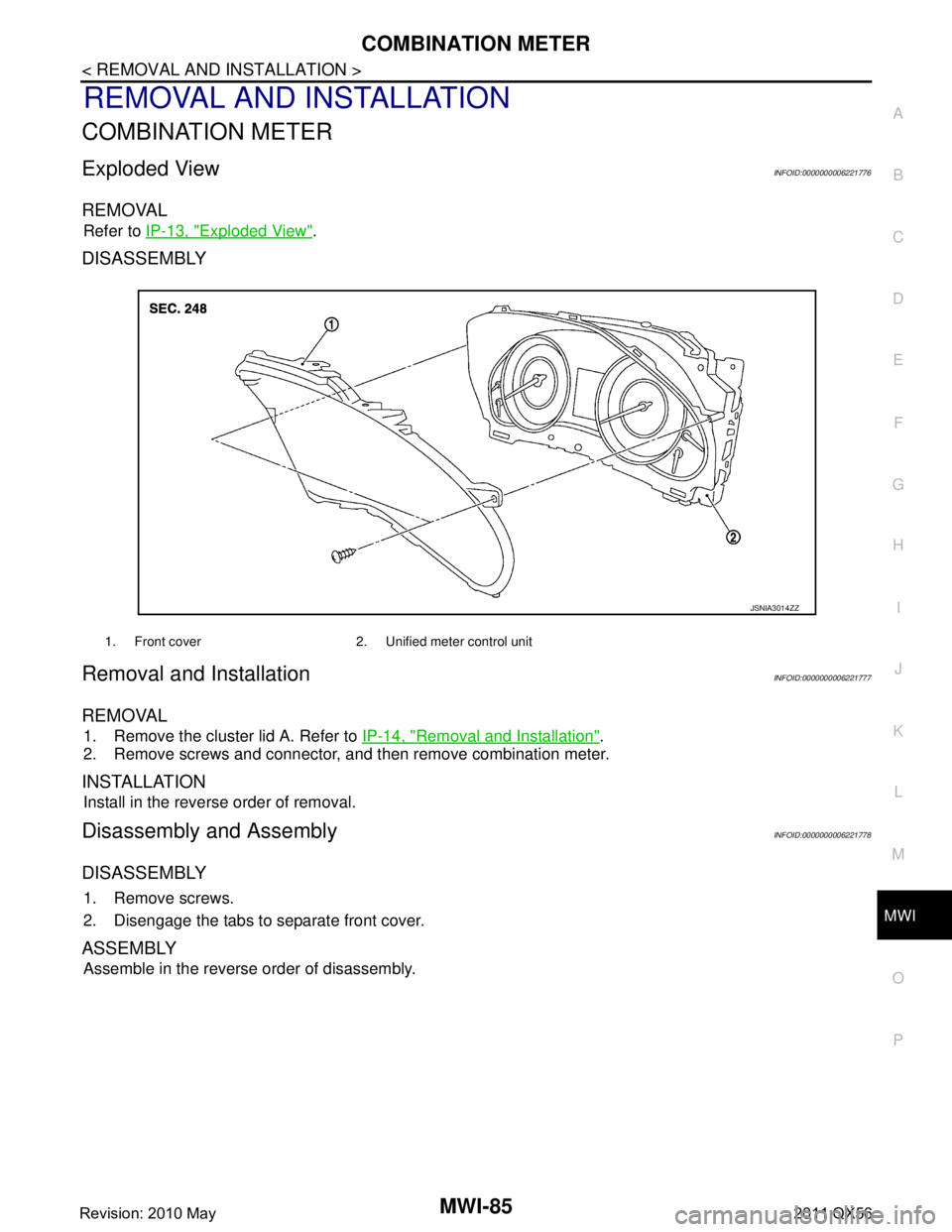
Exploded ViewINFOID:0000000006221776
REMOVAL
Refer to IP-13, "Exploded View".
DISASSEMBLY
Removal and InstallationINFOID:0000000006221777
REMOVAL
1. Remove the cluster lid A. Refer to IP-14, "Removal and Installation".
2. Remove screws and connector, and then remove combination meter.
INSTALLATION
Install in the reverse order of removal.
Disassembly and AssemblyINFOID:0000000006221778
DISASSEMBLY
1. Remove screws.
2. Disengage the tabs to separate front cover.
ASSEMBLY
Assemble in the reverse order of disassembly.
1. Front cover 2. Unified meter control unit
JSNIA3014ZZ
Revision: 2010 May2011 QX56
Page 3829 of 5598

MWI-86
< REMOVAL AND INSTALLATION >
TRIP RESET AND ILLUMINATION CONTROL SWITCH
TRIP RESET AND ILLUMINATION CONTROL SWITCH
Exploded ViewINFOID:0000000006221779
REMOVAL
Refer to IP-13, "Exploded View".
Removal and InstallationINFOID:0000000006221780
REMOVAL
1. Remove cluster lid A. Refer to IP-14, "Removal and Installation".
2. Remove clip.
3. Press pawls and remove trip reset and illumination control switch.
INSTALLATION
Install in the reverse order of removal.
Revision: 2010 May2011 QX56
Page 3830 of 5598
MWI
TRIP COMPUTER SWITCHMWI-87
< REMOVAL AND INSTALLATION >
C
DE
F
G H
I
J
K L
M B A
O P
TRIP COMPUTER SWITCH
Exploded ViewINFOID:0000000006221781
REMOVAL
Refer to IP-13, "Exploded View".
Removal and InstallationINFOID:0000000006221782
REMOVAL
1. Remove cluster lid A. Refer to IP-14, "Removal and Installation".
2. Press pawls and remove trip computer switch.
INSTALLATION
Install in the reverse order of removal.
Revision: 2010 May2011 QX56