ISUZU KB P190 2007 Workshop Repair Manual
Manufacturer: ISUZU, Model Year: 2007, Model line: KB P190, Model: ISUZU KB P190 2007Pages: 6020, PDF Size: 70.23 MB
Page 3141 of 6020
Engine Cooling – V6 Engine Page 6B1–6
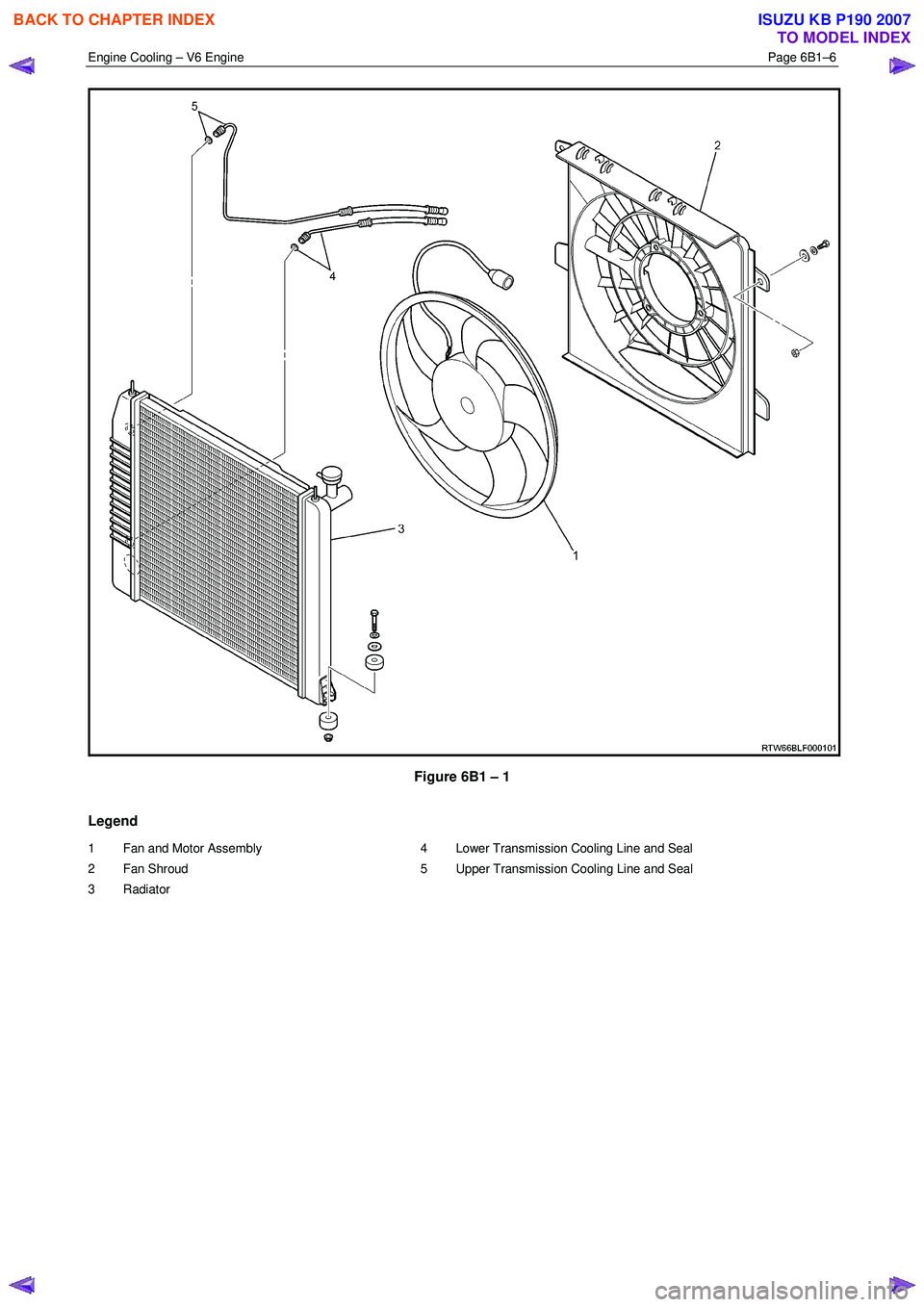
Figure 6B1 – 1
Legend
1 Fan and Motor Assembly
2 Fan Shroud
3 Radiator 4 Lower Transmission Cooling Line and Seal
5 Upper Transmission Cooling Line and Seal
BACK TO CHAPTER INDEX
TO MODEL INDEX
ISUZU KB P190 2007
Page 3142 of 6020
Engine Cooling – V6 Engine Page 6B1–7
2.2 Cooling Fan – Standard Specification
Overview
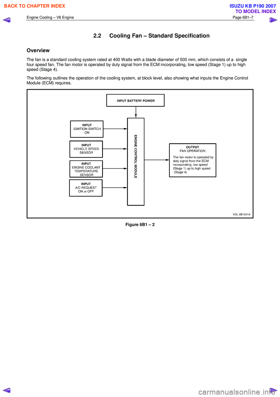
The fan is a standard cooling system rated at 400 W atts with a blade diameter of 500 mm, which consists of a single
four speed fan. The fan motor is operated by duty signal from the ECM incorporating, low speed (Stage 1) up to high
speed (Stage 4).
The following outlines the operation of the cooling system, at block level, also showing what inputs the Engine Control
Module (ECM) requires.
Figure 6B1 – 2
BACK TO CHAPTER INDEX
TO MODEL INDEX
ISUZU KB P190 2007
Page 3143 of 6020
Engine Cooling – V6 Engine Page 6B1–8
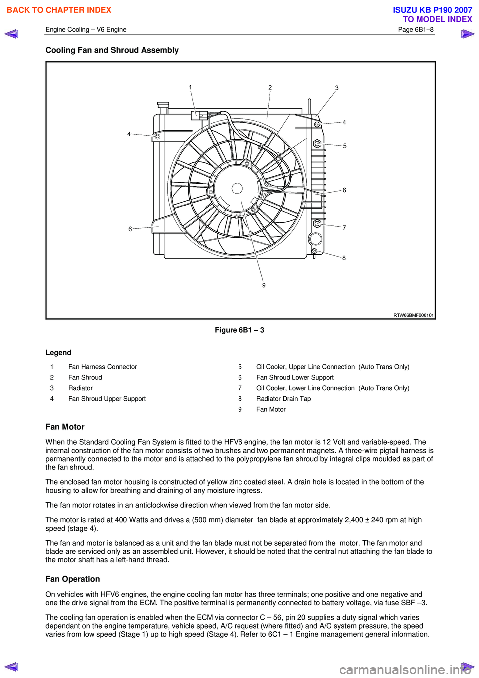
Cooling Fan and Shroud Assembly
Figure 6B1 – 3
Legend
1 Fan Harness Connector
2 Fan Shroud
3 Radiator
4 Fan Shroud Upper Support 5 Oil Cooler, Upper Line Connection (Auto Trans Only)
6 Fan Shroud Lower Support
7 Oil Cooler, Lower Line Connection (Auto Trans Only)
8 Radiator Drain Tap
9 Fan Motor
Fan Motor
W hen the Standard Cooling Fan System is fitted to the HFV6 engine, the fan motor is 12 Volt and variable-speed. The
internal construction of the fan motor consists of two brushes and two permanent magnets. A three-wire pigtail harness is
permanently connected to the motor and is attached to the polypropylene fan shroud by integral clips moulded as part of
the fan shroud.
The enclosed fan motor housing is constructed of yellow zinc coated steel. A drain hole is located in the bottom of the
housing to allow for breathing and draining of any moisture ingress.
The fan motor rotates in an anticlockwise direction when viewed from the fan motor side.
The motor is rated at 400 W atts and drives a (500 mm) diameter fan blade at approximately 2,400 ± 240 rpm at high
speed (stage 4).
The fan and motor is balanced as a unit and the fan blade must not be separated from the motor. The fan motor and
blade are serviced only as an assembled unit. However, it should be noted that the central nut attaching the fan blade to
the motor shaft has a left-hand thread.
Fan Operation
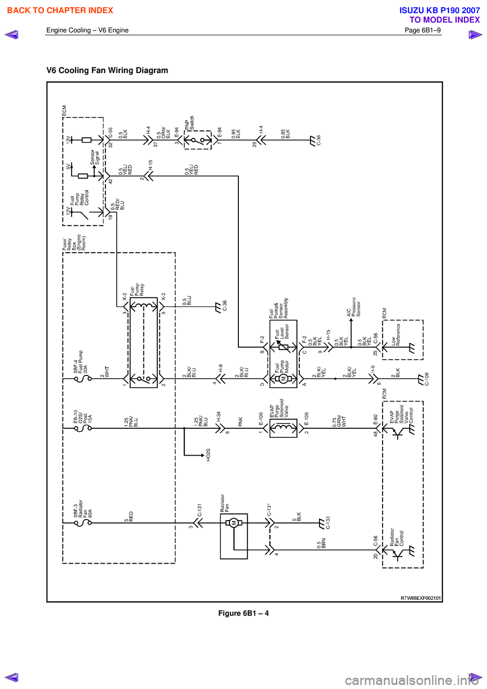
On vehicles with HFV6 engines, the engine cooling fan motor has three terminals; one positive and one negative and
one the drive signal from the ECM. The positive terminal is permanently connected to battery voltage, via fuse SBF –3.
The cooling fan operation is enabled when the ECM via connector C – 56, pin 20 supplies a duty signal which varies
dependant on the engine temperature, vehicle speed, A/C request (where fitted) and A/C system pressure, the speed
varies from low speed (Stage 1) up to high speed (Stage 4). Refer to 6C1 – 1 Engine management general information.
BACK TO CHAPTER INDEX
TO MODEL INDEX
ISUZU KB P190 2007
Page 3144 of 6020
Engine Cooling – V6 Engine Page 6B1–9
V6 Cooling Fan Wiring Diagram
Figure 6B1 – 4
BACK TO CHAPTER INDEX
TO MODEL INDEX
ISUZU KB P190 2007
Page 3145 of 6020

Engine Cooling – V6 Engine Page 6B1–10
Fan Assembly connector
Figure 6B1 – 5
2.3 Coolant Pump
The coolant pump is a centrifugal vane impeller type pump. The pump consists of a housing and an impeller. The
impeller is a flat plate mounted on the pump shaft with a series of flat or curved blades (vanes). W hen the impeller
rotates, the coolant between the vanes is thrown outward by centrifugal force. The impeller shaft is supported by sealed
bearings. The sealed bearings do not need to be lubricated. Grease cannot leak out, dirt and water cannot get in as long
as the seal is not damaged or worn.
The coolant pump (1) is mounted to the engine front cover
and is driven by the crankshaft pulley (2) via a multi-ribbed
drive belt (3), turning the pump pulley (4), bolted to the
coolant pump flange (5). Coolant enters the engine
through the coolant inlet pipe and thermostat at the rear of
engine and passes through the engine to the coolant
pump on the front engine cover and exits via the coolant
outlet housing (6) located at the front of the intake
manifold.
Figure 6B1 – 6
BACK TO CHAPTER INDEX
TO MODEL INDEX
ISUZU KB P190 2007
Page 3146 of 6020

Engine Cooling – V6 Engine Page 6B1–11
2.4 Coolant Outlet Housing
The coolant outlet housing (1) is located at the front of the
intake manifold (2).
Figure 6B1 – 7
2.5 Thermostat
The thermostat housing (1) is located at the rear of the
engine between the coolant inlet pipe (2) and the rear of
the intake manifold, underneath the heater pipe assembly
(3).
Figure 6B1 – 8
BACK TO CHAPTER INDEX
TO MODEL INDEX
ISUZU KB P190 2007
Page 3147 of 6020
Engine Cooling – V6 Engine Page 6B1–12
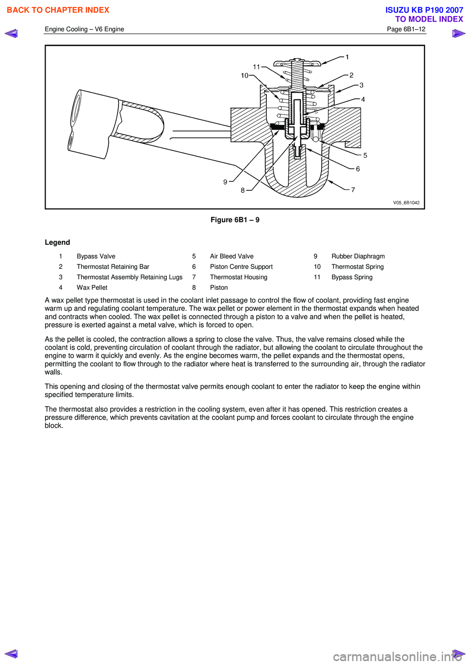
Figure 6B1 – 9
Legend
1 Bypass Valve
2 Thermostat Retaining Bar
3 Thermostat Assembly Retaining Lugs
4 Wax Pellet 5 Air Bleed Valve
6 Piston Centre Support
7 Thermostat Housing
8 Piston 9 Rubber Diaphragm
10 Thermostat Spring
11 Bypass Spring
A wax pellet type thermostat is used in the coolant inlet passage to control the flow of coolant, providing fast engine
warm up and regulating coolant temperature. The wax pellet or power element in the thermostat expands when heated
and contracts when cooled. The wax pellet is connected through a piston to a valve and when the pellet is heated,
pressure is exerted against a metal valve, which is forced to open.
As the pellet is cooled, the contraction allows a spring to close the valve. Thus, the valve remains closed while the
coolant is cold, preventing circulation of coolant through the radiator, but allowing the coolant to circulate throughout the
engine to warm it quickly and evenly. As the engine becomes warm, the pellet expands and the thermostat opens,
permitting the coolant to flow through to the radiator where heat is transferred to the surrounding air, through the radiator
walls.
This opening and closing of the thermostat valve permits enough coolant to enter the radiator to keep the engine within
specified temperature limits.
The thermostat also provides a restriction in the cooling system, even after it has opened. This restriction creates a
pressure difference, which prevents cavitation at the coolant pump and forces coolant to circulate through the engine
block.
BACK TO CHAPTER INDEX
TO MODEL INDEX
ISUZU KB P190 2007
Page 3148 of 6020

Engine Cooling – V6 Engine Page 6B1–13
2.6 Coolant Filler Cap
Figure 6B1 – 10 Figure 6B1 – 11
The pressurised coolant filler cap (1), fitted to the filler neck (2) on the coolant outlet housing, causes the cooling system
to operate at higher than atmospheric pressure. The higher pressure raises the boiling point of the coolant, resulting in
increased engine cooling efficiency. The coolant filler cap contains a pressure valve (3) and a vacuum (atmospheric)
valve (4).
Referring to view ‘A’, the pressure valve is held against its seat by a spring (5), which determines the maximum operating
pressure of the cooling system (120 kPa ).
Referring to view ‘B’, the vacuum valve (4) is held against its seat by a light spring and opens during cool down because
of the drop in pressure with contraction of the coolant volume. This pressure drop over-comes the spring force and the
vacuum valve is opened, preventing the radiator hoses from collapsing. In addition, coolant can also flow back into the
cooling system from the coolant recovery reservoir while this valve is open maintaining a full volume of coolant within the
engine and radiator.
Should the radiator pressure cap require
replacement, only fit the correct cap (with the
correct pressure-rating) for this engine. Refer
to the current release of Partfinder™ for this
information.
BACK TO CHAPTER INDEX
TO MODEL INDEX
ISUZU KB P190 2007
Page 3149 of 6020

Engine Cooling – V6 Engine Page 6B1–14
2.7 Coolant Recovery Reservoir
The coolant is maintained at the ideal level in the radiator by the coolant filler cap and the coolant recovery reservoir,
resulting in increased cooling efficiency.
The coolant recovery reservoir is located on the left-hand side front of the engine compartment, between the radiator
support panel and air cleaner assembly. The coolant recovery reservoir is connected to the radiator overflow connection
by a small diameter hose.
As the engine temperature rises, the coolant is heated and expands. The fluid displaced by expansion flows from the
radiator into the recovery reservoir.
W hen the engine is turned OFF, the coolant contracts as it cools. Coolant is then drawn back into the radiator through
the coolant filler cap atmospheric valve.
Coolant level should be maintained between the MAX and
MIN indicator lines on the coolant recovery reservoir, as
shown in Figure 6B1 – 12, when the engine is cold.
The cooling system is designed to use a coolant, DEX-
COOL® long-life coolant or equivalent to GM specification
6277M (a mixture of ethylene glycol antifreeze and
corrosion inhibitors and water), rather than plain water to
maintain the integrity of the cooling system, and to prevent
oxidation occurring within the engine.
NOTE
Some HFV6 Series vehicle markets call for
DEX-COOL® long-life coolant and others for
its equivalent, known as Extended Life Anti-
freeze Coolant, conforming to GM specification
6277M. If in doubt regarding the correct
coolant to be used, refer to the Owner’s
Handbook.
Figure 6B1 – 12
BACK TO CHAPTER INDEX
TO MODEL INDEX
ISUZU KB P190 2007
Page 3150 of 6020

Engine Cooling – V6 Engine Page 6B1–15
2.8 Engine Coolant Temperature Sensor
An Engine Coolant Temperature (ECT) sensor (2) is
mounted in the left-hand side cylinder head, just above
the exhaust manifold. The ECT sensor is used in
conjunction with the instrument panel temperature gauge.
The ECT sensor generates a signal, which is used by the
engine management system for calculation of the various
engine management functions.
Figure 6B1 – 13 shows the wiring harness connector (1)
and the ECT sensor (2).
Refer to 6C1-1 Engine Management General Information
for further information on the ECT sensor.
Figure 6B1 – 13
BACK TO CHAPTER INDEX
TO MODEL INDEX
ISUZU KB P190 2007