ISUZU KB P190 2007 Workshop Repair Manual
Manufacturer: ISUZU, Model Year: 2007, Model line: KB P190, Model: ISUZU KB P190 2007Pages: 6020, PDF Size: 70.23 MB
Page 4541 of 6020
7A4-64 UNIT REPAIR (JR405E)
412-4B09
•
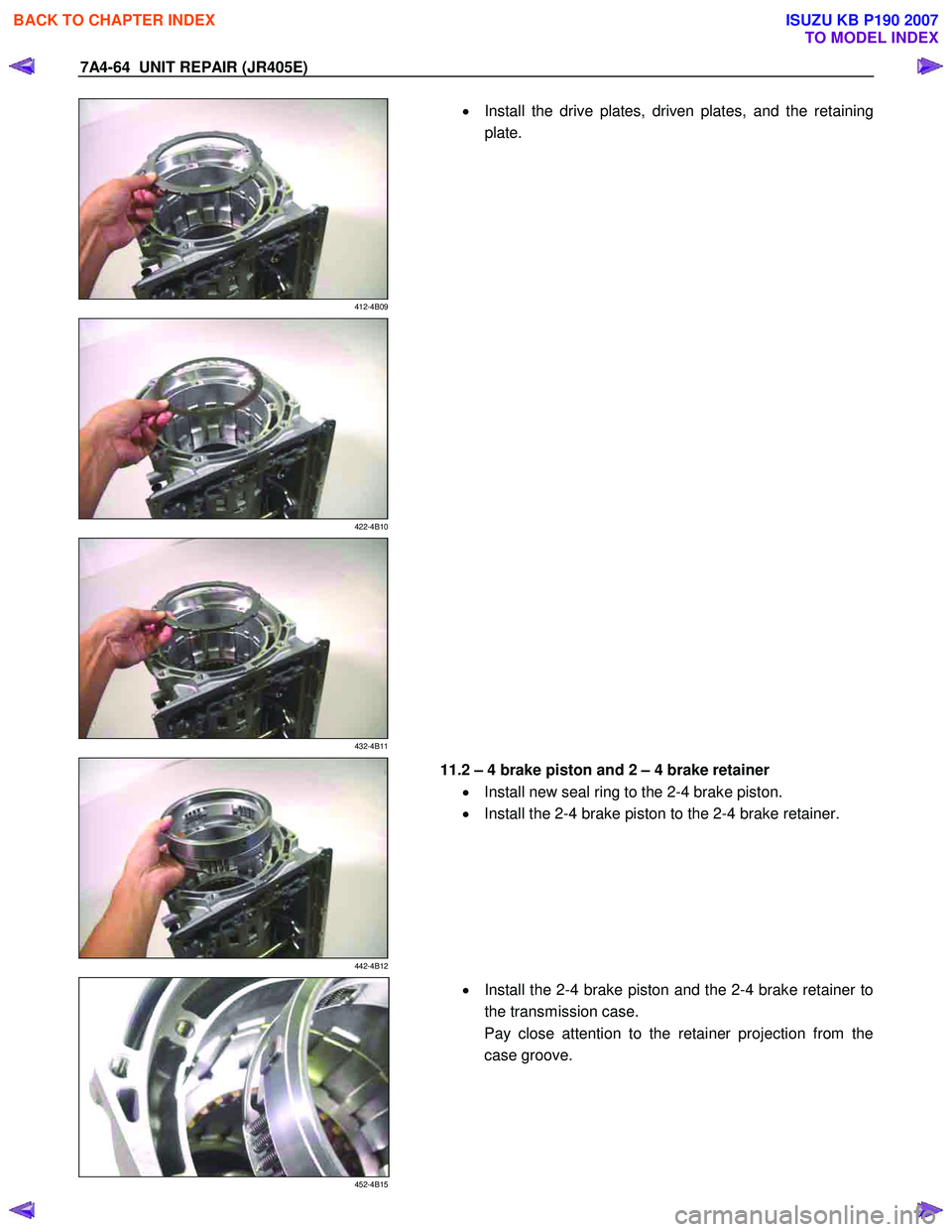
Install the drive plates, driven plates, and the retaining
plate.
422-4B10
432-4B11
442-4B12
11.2 – 4 brake piston and 2 – 4 brake retainer
• Install new seal ring to the 2-4 brake piston.
• Install the 2-4 brake piston to the 2-4 brake retainer.
452-4B15
•
Install the 2-4 brake piston and the 2-4 brake retainer to
the transmission case.
Pay close attention to the retainer projection from the
case groove.
BACK TO CHAPTER INDEX
TO MODEL INDEX
ISUZU KB P190 2007
Page 4542 of 6020
UNIT REPAIR (JR405E) 7A4-65
472-4B17
•
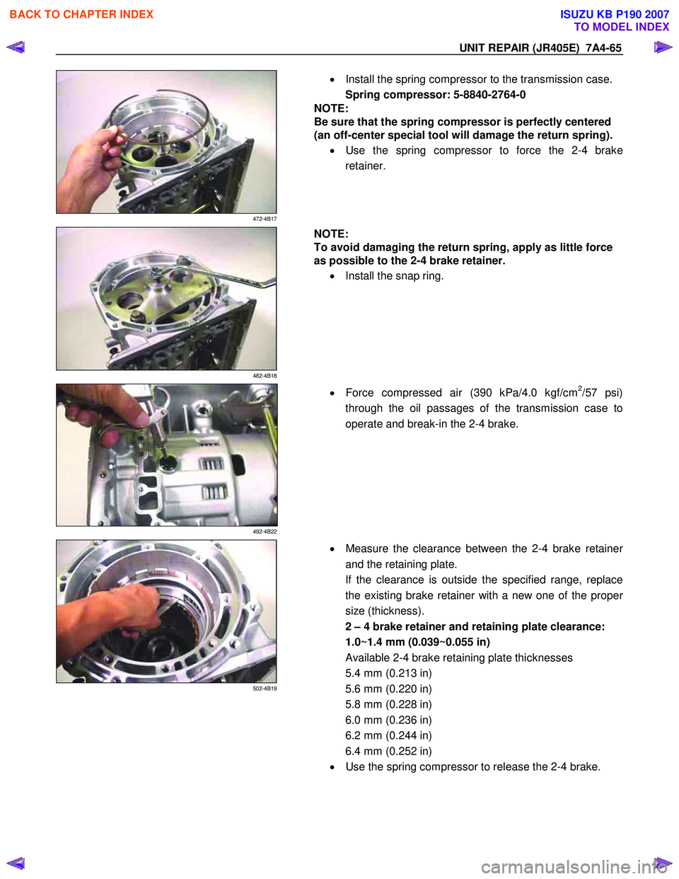
Install the spring compressor to the transmission case.
Spring compressor: 5-8840-2764-0
NOTE:
Be sure that the spring compressor is perfectly centered
(an off-center special tool will damage the return spring).
• Use the spring compressor to force the 2-4 brake
retainer.
482-4B18
NOTE:
To avoid damaging the return spring, apply as little force
as possible to the 2-4 brake retainer.
• Install the snap ring.
492-4B22
•
Force compressed air (390 kPa/4.0 kgf/cm2/57 psi)
through the oil passages of the transmission case to
operate and break-in the 2-4 brake.
502-4B19
•
Measure the clearance between the 2-4 brake retainer
and the retaining plate.
If the clearance is outside the specified range, replace
the existing brake retainer with a new one of the prope
r
size (thickness).
2 – 4 brake retainer and retaining plate clearance:
1.0~1.4 mm (0.039~0.055 in)
Available 2-4 brake retaining plate thicknesses
5.4 mm (0.213 in)
5.6 mm (0.220 in)
5.8 mm (0.228 in)
6.0 mm (0.236 in)
6.2 mm (0.244 in)
6.4 mm (0.252 in)
• Use the spring compressor to release the 2-4 brake.
BACK TO CHAPTER INDEX
TO MODEL INDEX
ISUZU KB P190 2007
Page 4543 of 6020
7A4-66 UNIT REPAIR (JR405E)
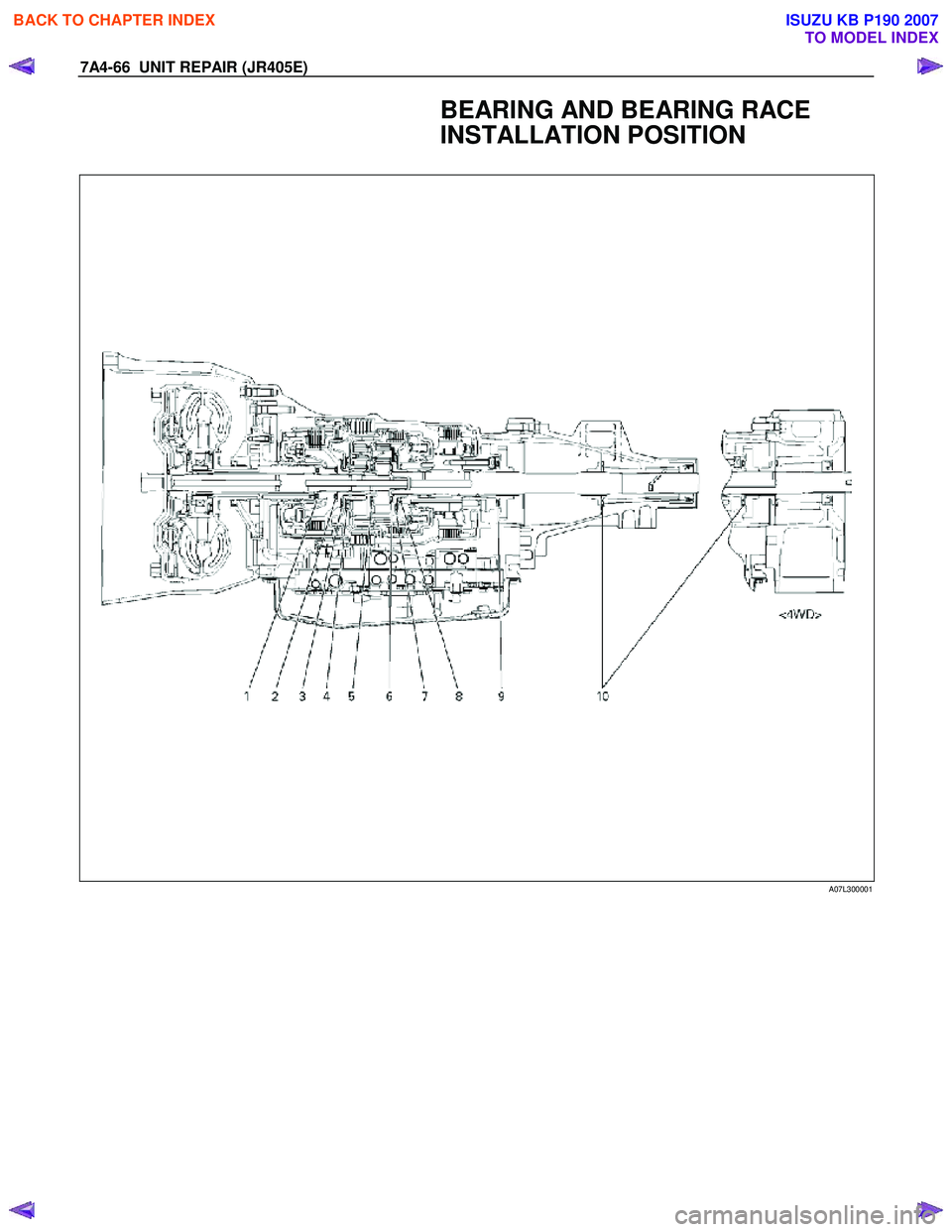
BEARING AND BEARING RACE
INSTALLATION POSITION
A07L300001
BACK TO CHAPTER INDEX
TO MODEL INDEX
ISUZU KB P190 2007
Page 4544 of 6020
UNIT REPAIR (JR405E) 7A4-67
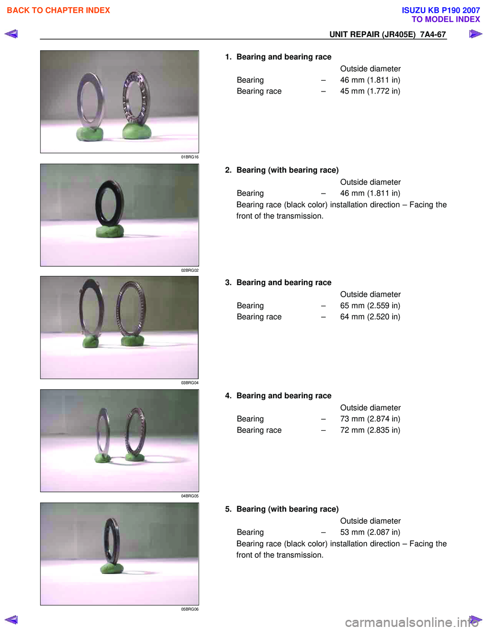
1. Bearing and bearing race
Outside diameter Bearing – 46 mm (1.811 in)
Bearing race – 45 mm (1.772 in)
01BRG16
2. Bearing (with bearing race)
Outside diameter
Bearing – 46 mm (1.811 in)
02BRG02
Bearing race (black color) installation direction – Facing the
front of the transmission.
3. Bearing and bearing race
Outside diameter Bearing – 65 mm (2.559 in)
Bearing race – 64 mm (2.520 in)
03BRG04
4. Bearing and bearing race
Outside diameter
Bearing – 73 mm (2.874 in)
Bearing race – 72 mm (2.835 in)
04BRG05
5. Bearing (with bearing race)
Outside diameter
Bearing – 53 mm (2.087 in)
05BRG06
Bearing race (black color) installation direction – Facing the
front of the transmission.
BACK TO CHAPTER INDEX
TO MODEL INDEX
ISUZU KB P190 2007
Page 4545 of 6020
7A4-68 UNIT REPAIR (JR405E)
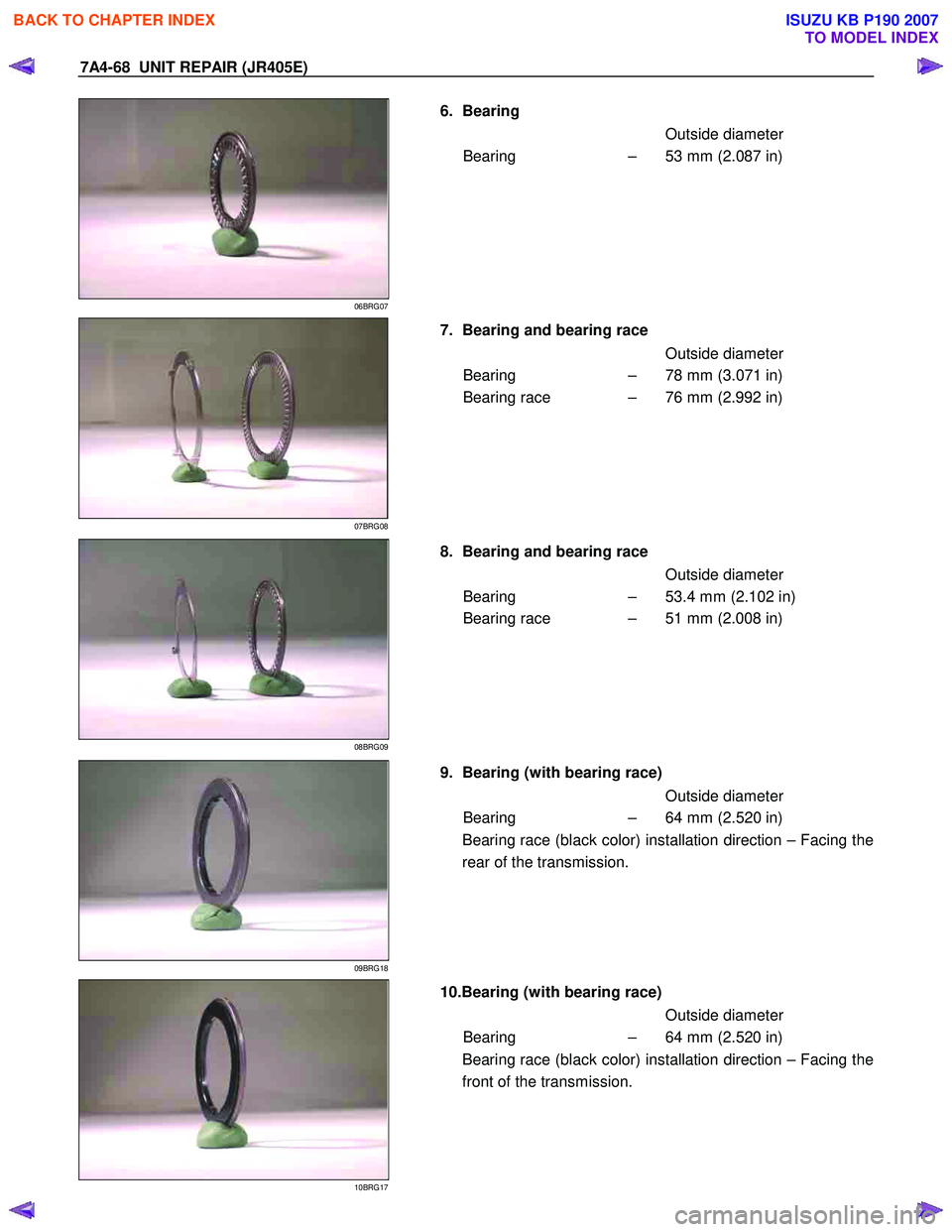
6. Bearing
Outside diameter
Bearing – 53 mm (2.087 in)
06BRG07
7. Bearing and bearing race
Outside diameter
Bearing – 78 mm (3.071 in)
Bearing race – 76 mm (2.992 in)
07BRG08
8. Bearing and bearing race
Outside diameter
Bearing – 53.4 mm (2.102 in)
Bearing race – 51 mm (2.008 in)
08BRG09
9. Bearing (with bearing race)
Outside diameter
Bearing – 64 mm (2.520 in)
09BRG18
Bearing race (black color) installation direction – Facing the
rear of the transmission.
10.Bearing (with bearing race)
Outside diameter
Bearing – 64 mm (2.520 in)
10BRG17
Bearing race (black color) installation direction – Facing the
front of the transmission.
BACK TO CHAPTER INDEX
TO MODEL INDEX
ISUZU KB P190 2007
Page 4546 of 6020
UNIT REPAIR (JR405E) 7A4-69
AUTOMATIC TRANSMISSION
REASSEMBLY
Assembly cautions
• Use your bare hands or vinyl gloves to reassemble the
transmission. Do not use ordinary work gloves (loosen
threads from the gloves may fall into the transmission
and cause problems).
• Before installing the drive plates, immerse them in the
recommended automatic transmission fluid (BESCO
ATF III). If the drive plate is new, it must be immersed
for at least two hours to ensure oil penetration and
saturation of the facing.
•
Apply ATF to all sliding and contact surfaces before
assembly. Also apply ATF to seal rings and O-rings.
Assemble the parts carefully to avoid damaging them.
• Replace any snap ring that appears worn, bent out o
f
shape, or damaged.
• If any part contacting the transmission case is damaged,
it must be replaced with a new part.
• Be careful not to damage the plates during reassembl
y
(oil leakage from the plate will result).
• If you are reusing a seal, remove the old adhesive agent
and clean the surface with cleaning oil before applying
the new adhesive agent.
• W ait at least two hours after installing the oil seals
before installing the plates.
• Do not replace O-rings, snap rings, bearings, and/o
r
bearing races with inferior substitutes.
BACK TO CHAPTER INDEX
TO MODEL INDEX
ISUZU KB P190 2007
Page 4547 of 6020
7A4-70 UNIT REPAIR (JR405E)
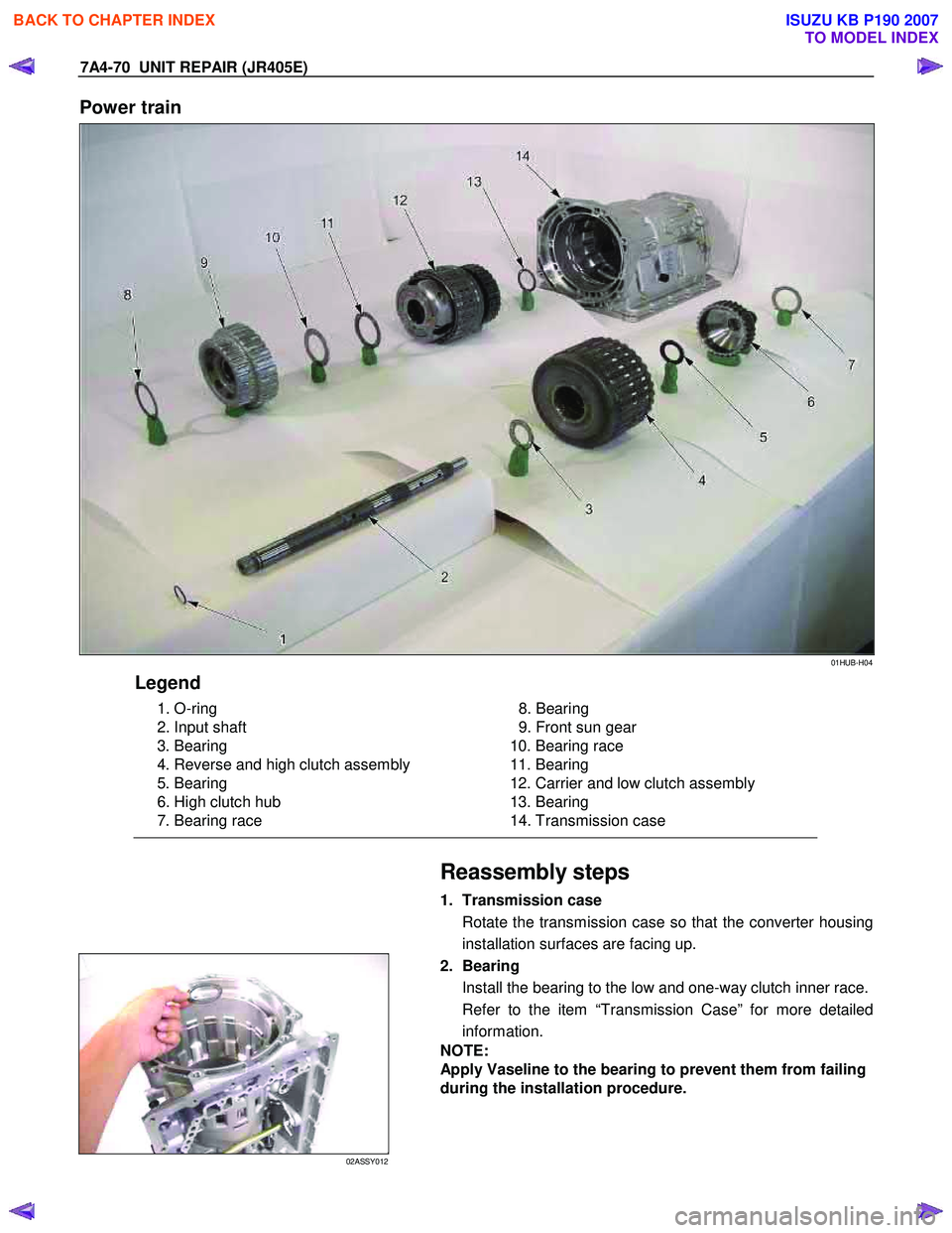
Power train
01HUB-H04
Legend
1. O-ring
2. Input shaft
3. Bearing
4. Reverse and high clutch assembly
5. Bearing
6. High clutch hub
7. Bearing race
8. Bearing
9. Front sun gear
10. Bearing race
11. Bearing
12. Carrier and low clutch assembly
13. Bearing
14. Transmission case
Reassembly steps
1. Transmission case
Rotate the transmission case so that the converter housing
installation surfaces are facing up.
02ASSY012
2. Bearing
Install the bearing to the low and one-way clutch inner race.
Refer to the item “Transmission Case” for more detailed
information.
NOTE:
Apply Vaseline to the bearing to prevent them from failing
during the installation procedure.
BACK TO CHAPTER INDEX
TO MODEL INDEX
ISUZU KB P190 2007
Page 4548 of 6020
UNIT REPAIR (JR405E) 7A4-71
03ASSY013
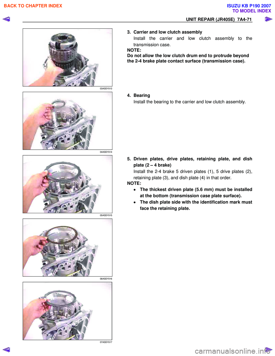
3. Carrier and low clutch assembly
Install the carrier and low clutch assembly to the
transmission case.
NOTE:
Do not allow the low clutch drum end to protrude beyond
the 2-4 brake plate contact surface (transmission case).
04ASSY014
4. Bearing
Install the bearing to the carrier and low clutch assembly.
05ASSY015
5. Driven plates, drive plates, retaining plate, and dish
plate (2 – 4 brake)
Install the 2-4 brake 5 driven plates (1), 5 drive plates (2),
retaining plate (3), and dish plate (4) in that order.
NOTE:
•
••
•
The thickest driven plate (5.6 mm) must be installed
at the bottom (transmission case plate surface).
•
••
•
The dish plate side with the identification mark must
face the retaining plate.
06ASSY016
07ASSY017
BACK TO CHAPTER INDEX
TO MODEL INDEX
ISUZU KB P190 2007
Page 4549 of 6020
7A4-72 UNIT REPAIR (JR405E)
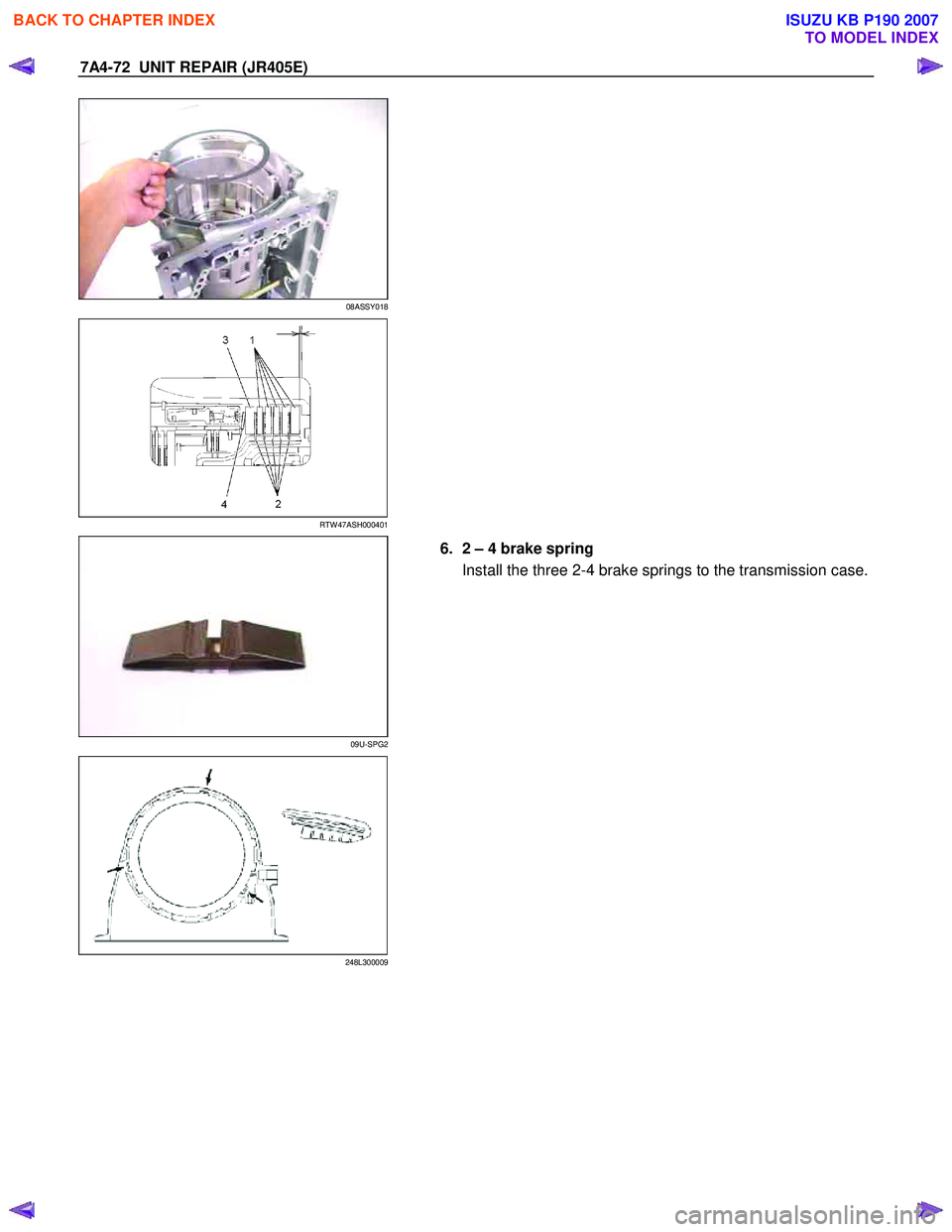
08ASSY018
RTW 47ASH000401
09U-SPG2
6. 2 – 4 brake spring
Install the three 2-4 brake springs to the transmission case.
248L300009
BACK TO CHAPTER INDEX
TO MODEL INDEX
ISUZU KB P190 2007
Page 4550 of 6020
UNIT REPAIR (JR405E) 7A4-73
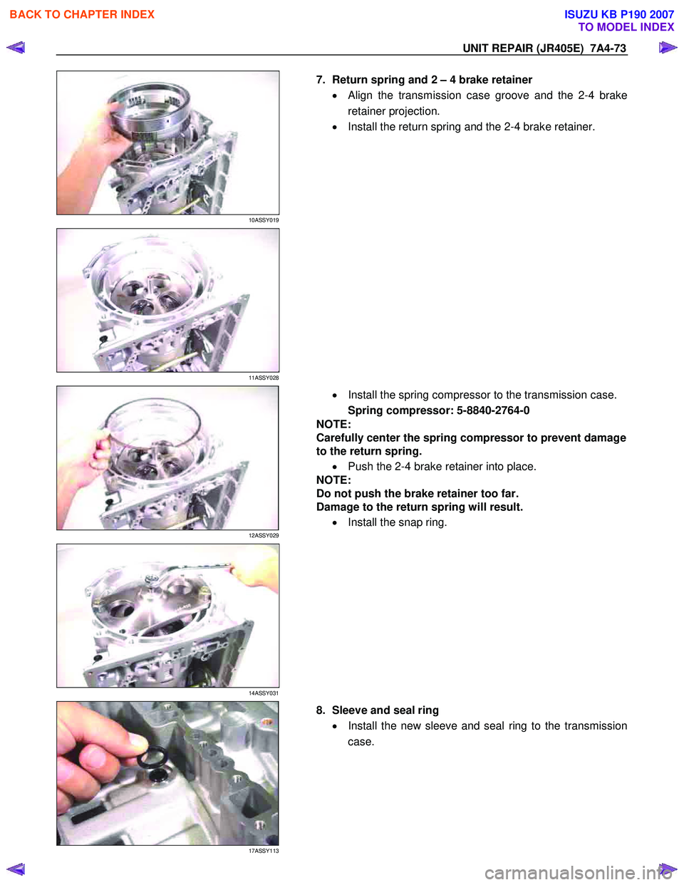
10ASSY019
7. Return spring and 2 – 4 brake retainer
• Align the transmission case groove and the 2-4 brake
retainer projection.
• Install the return spring and the 2-4 brake retainer.
11ASSY028
12ASSY029
• Install the spring compressor to the transmission case.
Spring compressor: 5-8840-2764-0
NOTE:
Carefully center the spring compressor to prevent damage
to the return spring.
• Push the 2-4 brake retainer into place.
NOTE:
Do not push the brake retainer too far.
Damage to the return spring will result.
• Install the snap ring.
14ASSY031
17ASSY113
8. Sleeve and seal ring
• Install the new sleeve and seal ring to the transmission
case.
BACK TO CHAPTER INDEX
TO MODEL INDEX
ISUZU KB P190 2007