ISUZU KB P190 2007 Workshop Repair Manual
Manufacturer: ISUZU, Model Year: 2007, Model line: KB P190, Model: ISUZU KB P190 2007Pages: 6020, PDF Size: 70.23 MB
Page 5211 of 6020

ELECTRICAL-BODY AND CHASSIS 8A-273
TROUBLESHOOTING
WINDSHIELD WIPER
1. Wiper dose not operate at any switch position
Checkpoint Trouble Cause Countermeasure
Reinstall or replace the fuse
No. C9 (20A)
Poor fuse contact or blown
NG
Repair open circuit or
connector contact
1. W iper motor function when
connecting the motor
connector 3
C4 to the
battery (+) terminal, and 1
C4 to the (-) terminal
(Should the wiper motor
rotate at a low speed)
2. W iper motor function when connecting the motor
connector 2
C4 to the
battery (+) terminal, 1
C4 to the (-) terminal
(Should the wiper motor
rotate at a high speed)
Voltage between 3 B59 and
the ground (Should be battery
v oltage present)
Open circuit or poor connector
contact
Replace the wiper & washer
SW .
Continuity in the wiper &
washer SW .
SW . malfunction
NG
NG
OK
OK
Fuse No. C9 (20A)
Repair grounding point
contact
Grounding point
C2 (LHD),
C
C36 (RHD)
Poor grounding point contact
NG
OK
OK
Replace the wiper motor
W iper motor malfunction
NG
Repair open circuit or
connector contact
Continuity between 1
C4
and
C36 (RHD), C2 (LHD)
Open circuit or poor connector
contact
NG
OK
BACK TO CHAPTER INDEX
TO MODEL INDEXISUZU KB P190 2007
Page 5212 of 6020

8A-274 ELECTRICAL-BODY AND CHASSIS
2. Wiper dose not operate at “ INT “ position
Checkpoint Trouble Cause Countermeasure
Replace the wiper & washer
SW .
SW . malfunction
NG
Repair grounding point contact
Grounding point
C36 (RHD),
C2 (LHD)
Poor grounding point contact
Repair open circuit or
connector contact
Voltage between the
intermittent relay harness side
connector terminal 4
C3
and the ground at the “INT”
position (Should be battery
voltage present)
Open circuit or poor connector
contact
NG
NG
OK
OK
Continuity between the wiper
& washer SW connector
terminals 4
B59 and 2 B59
at the “ INT “ position
Replace the intermittent relay
Intermittent relay function
Relay malfunction
NG
OK
3. Wiper does not operate at “LO” position
Replace the wiper motor
W iper motor function
1. Disconnect the wiper & washer SW . connector
2. Turn the starter SW . on
3. Short-circuit between the wiper & washer SW .
harness side connector terminal 3
B59 and
5
B59 .
4. Check to see if the wiper
motor rotates at a low
speed
W iper motor malfunction
NG
Replace the wiper & washer
SW .
W iper & washer SW . function
SW . malfunction
NG
OK
BACK TO CHAPTER INDEX TO MODEL INDEXISUZU KB P190 2007
Page 5213 of 6020

ELECTRICAL-BODY AND CHASSIS 8A-275
4. Wiper does not operate at “HI” position
Checkpoint Trouble Cause Countermeasure
Repair open circuit or
connector contact
Open circuit or poor connector
contact
NG
Replace the wiper motor
W iper motor function when
connecting the motor
connector 2
C4 to the
battery (+) terminal, and 1
C4 to the (-) terminal
(Should the wiper motor rotate
at a high speed)
W iper motor malfunction
NG
OK
Continuity between the wiper
& washer SW . connector
terminals 4
B59 at the “HI”
position
Repair open circuit or
connector contact
Continuity between 4
B59
and 2
C4
Open circuit or poor connector
contact
NG
OK
5. Rotation of the wiper motor does not stop
Replace the wiper & washer
SW .
SW . malfunction
NG
OK
Continuity in the wiper &
washer SW .
Replace the wiper motor
W iper motor function
W iper motor malfunction
NG
BACK TO CHAPTER INDEX
TO MODEL INDEXISUZU KB P190 2007
Page 5214 of 6020

8A-276 ELECTRICAL-BODY AND CHASSIS
6. Auto-stop function of the wiper motor does not operate
Checkpoint Trouble Cause Countermeasure
Repair open circuit or
connector contact
Open circuit or poor connector
contact
NG
Repair open circuit or
connector contact
Open circuit or poor connector
contact
NG Continuity between the
intermittent relay harness side
connector 6
C3 and the
wiper motor harness side
connector 6
C4
Replace the intermittent relay
Relay malfunction
NG
Intermittent relay function
W iper motor function
1. Disconnect the wiper motor connector
2. Connect the motor connector 5
B59 to the
battery (+) terminal and
1
C4 to the (-) terminal,
and then change the
connection of the battery (+)
terminal to the connector
4
C4 while the motor
rotating at a low speed
3. Check to see if the wiper motor stops at the auto stop
position when connecting
the connector terminals
3
C4 and 1 C4 in this
condition
Continuity between the wiper
& washer SW . connector
terminals 5
B59 and 6 B59
at the “OFF” position
OK
Replace the wiper motor
W iper motor malfunction
NG
Repair an open circuit or a
poor connection of the
connectors between the fuse
No. C9 (20A) and 4
C4
Voltage between the wiper
motor harness side connector
terminal 4
C4 and the
ground (Should be battery
v oltage present)
Open circuit or poor connector
contact
NG
OK
OK
OK
BACK TO CHAPTER INDEX
TO MODEL INDEXISUZU KB P190 2007
Page 5215 of 6020

ELECTRICAL-BODY AND CHASSIS 8A-277
WASHER
1. Washer motor does not operate
Checkpoint Trouble Cause Countermeasure
Reinstall or replace the fuse
No. C9 (20A)
Poor fuse contact or blown
NG
Repair or an open circuit or a
poor connection of the
connectors between 2
C17
and 1
B59
Open circuit or poor connector
contact
NG Voltage between the washer
motor harness side connector
terminal 2
C17 and the
ground when the washer
button is depressed (Should
be battery v oltage present)
Repair grounding point
C36
contact
Poor grounding point contact
NG
Grounding point
C36
Replace the washer motor
Motor malfunction
NG
W asher motor function when
connecting the motor side
connector 2
C17 to the
battery (+) terminal, and the
connector 1
C17 to the (-)
terminal (Should the washer
motor rotate) OK
Repair open circuit or
connector contact
Open circuit or poor connector
contact
NG
Continuity between 1
C17
and
C36
OK
Continuity between the wiper
& washer SW . side connector
terminals 1
B59 and 7 B59
when the washer button is
depressed
Fuse No. C9 (20A)
OK
Replace the wiper & washer
SW .
SW . malfunction
NG
Repair or an open circuit or a
poor connection of the
connectors between the fuse
No. C-9 (20A) and 7
B59
Voltage between the wiper &
washer SW . harness side
connector terminal 7
B59
and the ground (Should be
battery v oltage preset)
Open circuit or poor connector
contact
NG
OK
OK
OK
BACK TO CHAPTER INDEX
TO MODEL INDEXISUZU KB P190 2007
Page 5216 of 6020

8A-278 ELECTRICAL-BODY AND CHASSIS
REMOVAL AND INSTALLATION
WIPER AND WASHER SWITCH
Removal
Refer to the removal steps of the LIGHTING SW ITCH
(COMBINATION SW ITCH) in “ LIGHTING “ of this section.
Installation
Follow the removal procedure in the reverse order to install the
wiper and washer switch.
RTW 780SH001601
This illustration is based on RHD model
Pay close attention to the important points mentioned in the
following paragraphs.
Connector
Be absolutely sure that the wiper and washer switch connector
is securely connected.
This will prevent a poor contact and an open circuit.
BACK TO CHAPTER INDEX TO MODEL INDEXISUZU KB P190 2007
Page 5217 of 6020

ELECTRICAL-BODY AND CHASSIS 8A-279
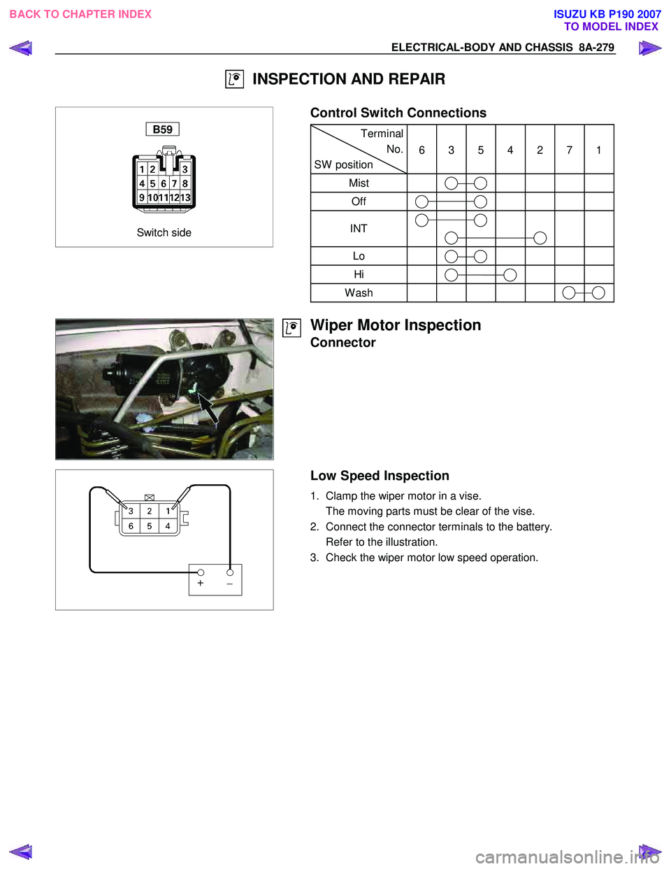
INSPECTION AND REPAIR
Switch side
B59
Control Switch Connections
Terminal
No.
SW position 6 3 5 4 2 7 1
Mist
Off
INT
Lo
Hi
Wash
Wiper Motor Inspection
Connector
Low Speed Inspection
1. Clamp the wiper motor in a vise.
The moving parts must be clear of the vise.
2. Connect the connector terminals to the battery.
Refer to the illustration.
3. Check the wiper motor low speed operation.
BACK TO CHAPTER INDEX TO MODEL INDEXISUZU KB P190 2007
Page 5218 of 6020

8A-280 ELECTRICAL-BODY AND CHASSIS
High Speed Inspection
1. Clamp the wiper motor in a vise.
The moving parts must be clear of the vise.
2. Connect the connector terminals to the battery.
Refer to the illustration.
3. Check the wiper motor high speed operation.
Auto-Stop Inspection
1. Clamp the wiper motor in a vise.
The moving parts must be clear of the vise.
2. Connect the connector terminals to the battery.
Refer to the illustration.
3. Check the wiper motor low speed operation.
4. Disconnect the positive battery terminal.
This will stop the motor.
5. Connect the connector terminals No. 3 and No. 6 with a
lead wire.
Refer to the illustration.
6. Reconnect the positive battery terminal to connecto
r
terminal No. 4.
This will restart the motor.
Refer to the illustration.
7. Check the auto-stop operation.
Washer Motor Inspection
1. Fill the washer tank with washing solution.
2. Disconnect the motor connector.
3. Apply battery voltage to the washer motor connector.
4. Check the washer motor operation.
BACK TO CHAPTER INDEX TO MODEL INDEXISUZU KB P190 2007
Page 5219 of 6020

ELECTRICAL-BODY AND CHASSIS 8A-281
WIPER MOTOR AND LINKAGE
Removal
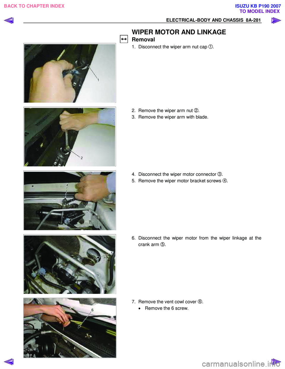
1. Disconnect the wiper arm nut cap
1 .
2. Remove the wiper arm nut
2.
3. Remove the wiper arm with blade.
4. Disconnect the wiper motor connector 3 .
5. Remove the wiper motor bracket screws
4 .
6. Disconnect the wiper motor from the wiper linkage at the
crank arm
5.
7. Remove the vent cowl cover
6.
• Remove the 6 screw.
BACK TO CHAPTER INDEX TO MODEL INDEXISUZU KB P190 2007
Page 5220 of 6020

8A-282 ELECTRICAL-BODY AND CHASSIS
This illustration is based on RHD model
8. Remove the wiper linkage
7 from the access hole.
Installation
Follow the removal procedure in the reverse order to install the
wiper motor and linkage.
Pay close attention to the important points mentioned in the
following paragraphs.
Wiper Linkage
Take care not to scratch the painted surfaces of the body when
installing the wiper linkage to the body.
In case crank arm of wiper motor is removed, confirm the
position of auto stop prior to reinstall the crank arm to the wiper
motor.
Crank Arm Nut Torque N⋅m (kg ⋅m/lb ft
)
20 − 26 (2.0 − 2.6 / 14.5 − 18.8)
880R300006
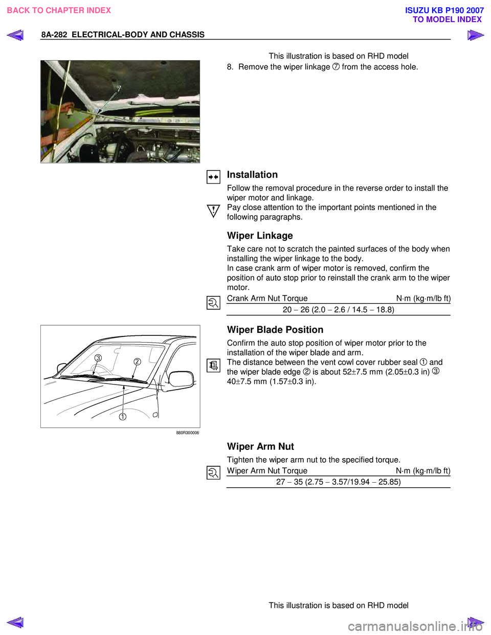
Wiper Blade Position
Confirm the auto stop position of wiper motor prior to the
installation of the wiper blade and arm.
The distance between the vent cowl cover rubber seal
1 and
the wiper blade edge
2 is about 52±7.5 mm (2.05 ±0.3 in) 3
40 ±7.5 mm (1.57 ±0.3 in).
Wiper Arm Nut
Tighten the wiper arm nut to the specified torque.
W iper Arm Nut Torque N ⋅m (kg ⋅m/lb ft)
27 − 35 (2.75 − 3.57/19.94 − 25.85)
This illustration is based on RHD model
BACK TO CHAPTER INDEX
TO MODEL INDEXISUZU KB P190 2007