ISUZU KB P190 2007 Workshop Repair Manual
KB P190 2007
ISUZU
ISUZU
https://www.carmanualsonline.info/img/61/57177/w960_57177-0.png
ISUZU KB P190 2007 Workshop Repair Manual
Trending: engine mount, radio antenna, fog light bulb, trans, air filter, Alternator, change key battery
Page 5781 of 6020
CAB 10-23
4. Bracket
5. Speaker assembly • Remove the fixing bolt and then remove the connector.
6. Waterproof Sheet • Take care not to damage the sheet when peeling it off.
7. Inside Lever • Disconnect the door lock cables.
8. Outer Waste Seal
9. Glass Run Rear Channel • Remove the bolt.
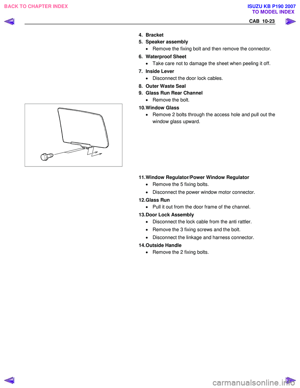
10. Window Glass
• Remove 2 bolts through the access hole and pull out the
window glass upward.
11. Window Regulator/Power Window Regulator
• Remove the 5 fixing bolts.
• Disconnect the power window motor connector.
12. Glass Run • Pull it out from the door frame of the channel.
13. Door Lock Assembly • Disconnect the lock cable from the anti rattler.
• Remove the 3 fixing screws and the bolt.
• Disconnect the linkage and harness connector.
14. Outside Handle • Remove the 2 fixing bolts.
BACK TO CHAPTER INDEX
TO MODEL INDEX
ISUZU KB P190 2007
Page 5782 of 6020
10-24 CAB
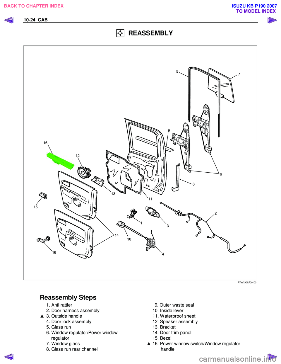
REASSEMBLY
7
6
2
3
1
10 4
14
13
11
12
16
15
8
9 5
16
RTW 7A0LF001001
Reassembly Steps
1. Anti rattler
2. Door harness assembly
▲ 3. Outside handle
4. Door lock assembly
5. Glass run
6. W indow regulator/Power window regulator
7. W indow glass
8. Glass run rear channel
9. Outer waste seal
10. Inside lever
11. W aterproof sheet
12. Speaker assembly
13. Bracket
14. Door trim panel
15. Bezel
▲ 16. Power window switch/W indow regulator
handle
BACK TO CHAPTER INDEX TO MODEL INDEX
ISUZU KB P190 2007
Page 5783 of 6020
CAB 10-25
Important Operations
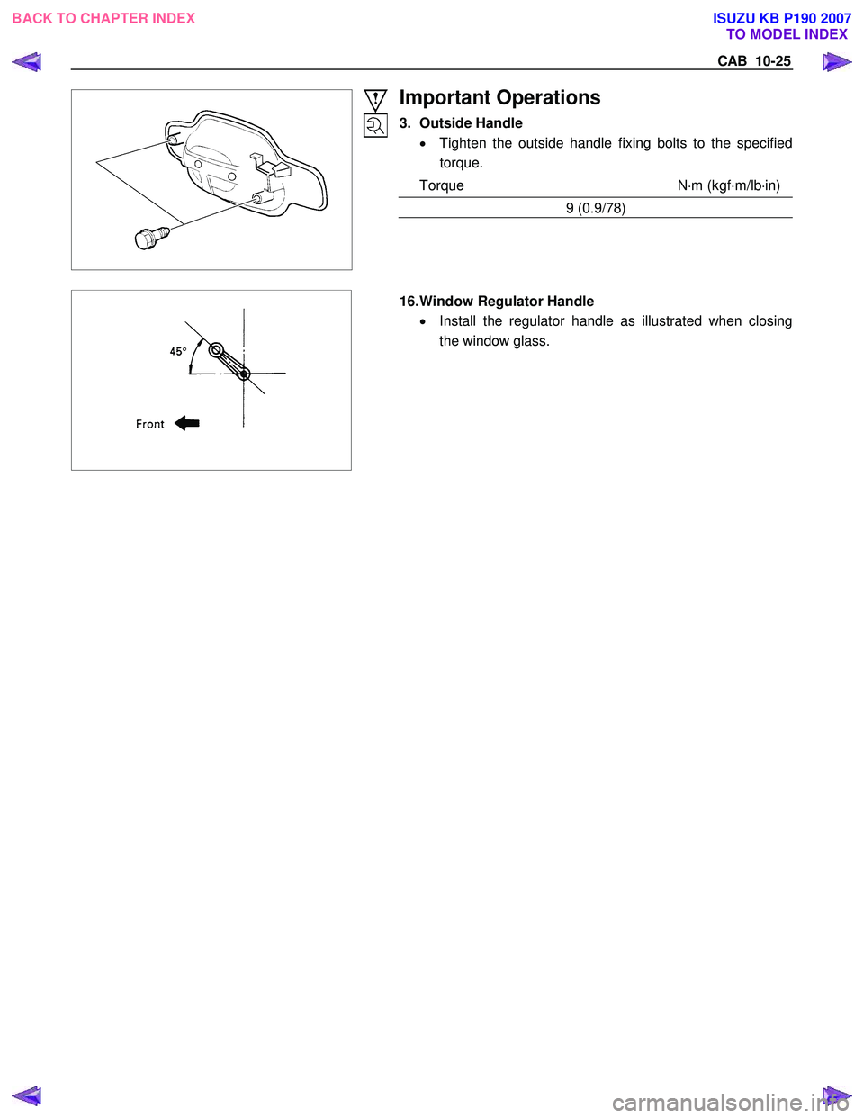
3. Outside Handle • Tighten the outside handle fixing bolts to the specified
torque.
Torque N ⋅m (kgf ⋅m/lb ⋅in)
9 (0.9/78)
16. Window Regulator Handle
• Install the regulator handle as illustrated when closing
the window glass.
BACK TO CHAPTER INDEX TO MODEL INDEX
ISUZU KB P190 2007
Page 5784 of 6020
10-26 CAB
ADJUSTMENT (REAR)
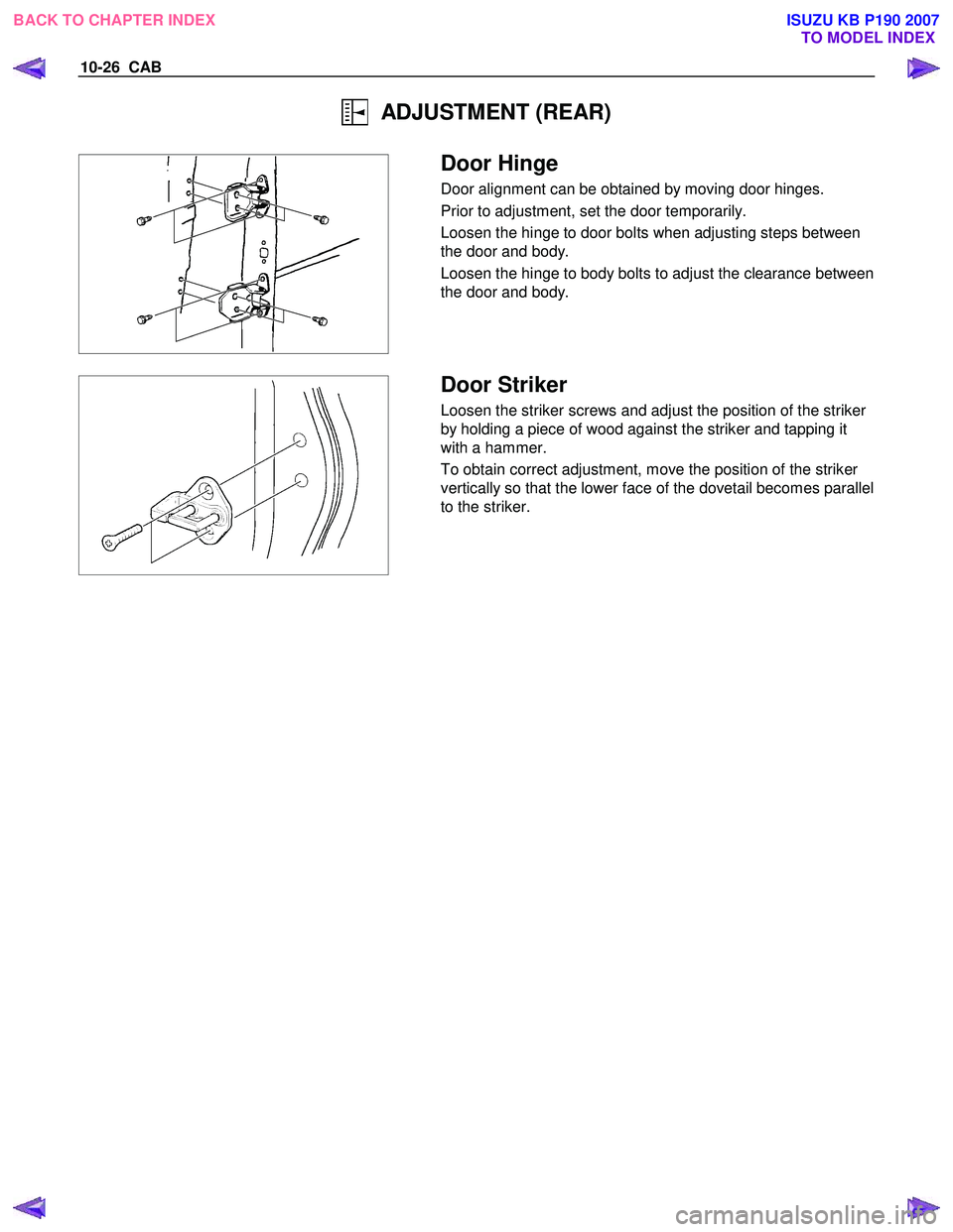
Door Hinge
Door alignment can be obtained by moving door hinges.
Prior to adjustment, set the door temporarily.
Loosen the hinge to door bolts when adjusting steps between
the door and body.
Loosen the hinge to body bolts to adjust the clearance between
the door and body.
Door Striker
Loosen the striker screws and adjust the position of the striker
by holding a piece of wood against the striker and tapping it
with a hammer.
To obtain correct adjustment, move the position of the striker
vertically so that the lower face of the dovetail becomes parallel
to the striker.
BACK TO CHAPTER INDEX TO MODEL INDEX
ISUZU KB P190 2007
Page 5785 of 6020
CAB 10-27
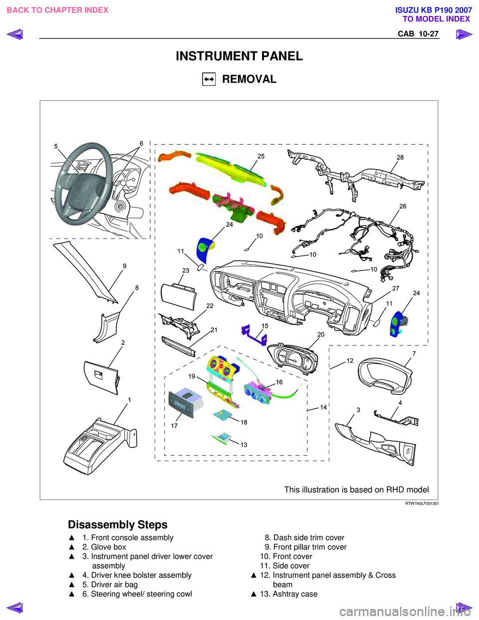
INSTRUMENT PANEL
REMOVAL
9
8
2
1
7
4
3
12
2120
15
19
22
18
14
16
13
17
24
23
11
2528
26
24
10
10
27
11
5 6
10
This illustration is based on RHD model RTW 7A0LF001301
Disassembly Steps
▲
1. Front console assembly
▲ 2. Glove box
▲ 3. Instrument panel driver lower cover
assembly
▲ 4. Driver knee bolster assembly
▲ 5. Driver air bag
▲ 6. Steering wheel/ steering cowl
8. Dash side trim cover
9. Front pillar trim cover
10. Front cover
11. Side cover
▲ 12. Instrument panel assembly & Cross
beam
▲ 13. Ashtray case
BACK TO CHAPTER INDEX
TO MODEL INDEX
ISUZU KB P190 2007
Page 5786 of 6020
10-28 CAB
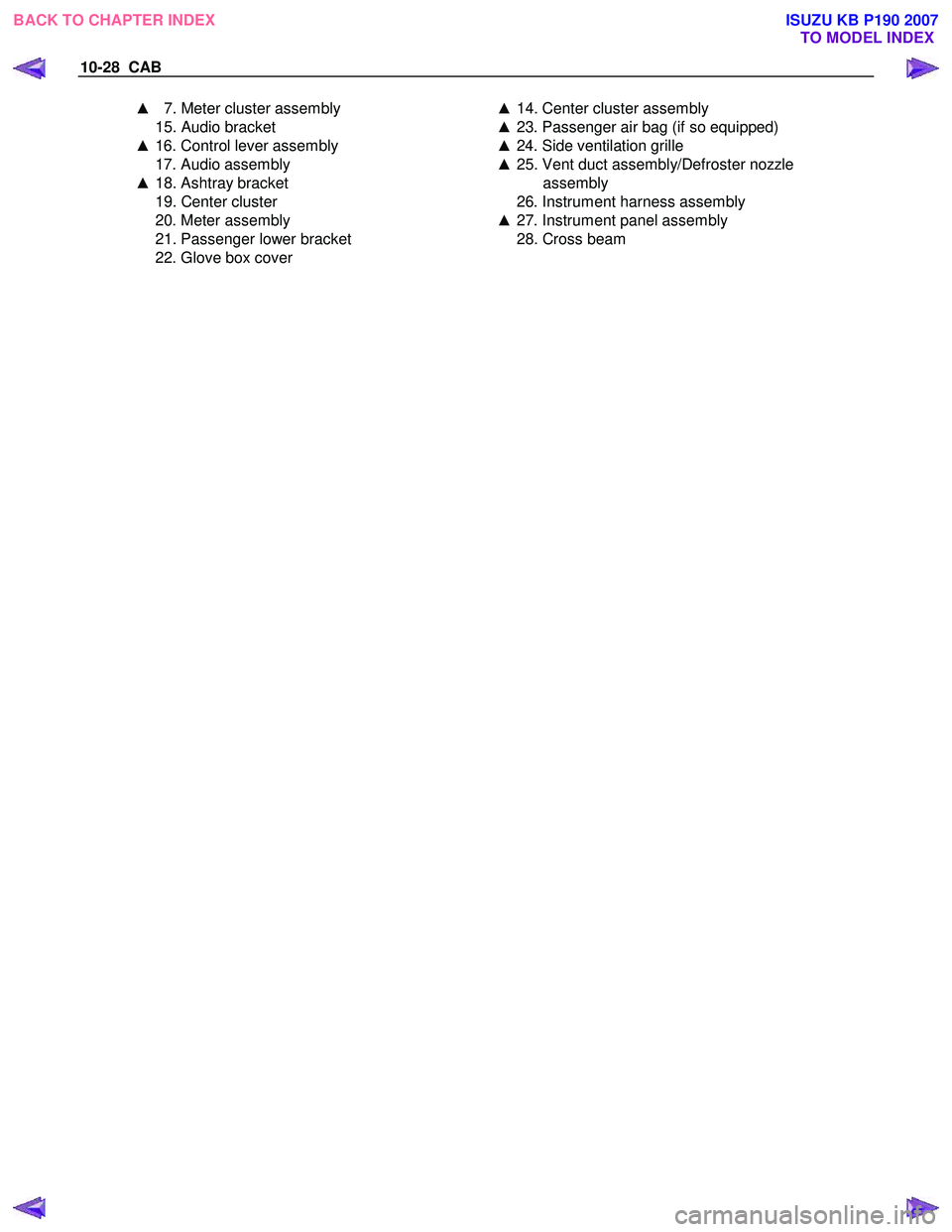
▲ 7. Meter cluster assembly ▲ 14. Center cluster assembly
15. Audio bracket
▲ 16. Control lever assembly
17. Audio assembly
▲ 18. Ashtray bracket
19. Center cluster
20. Meter assembly
21. Passenger lower bracket
22. Glove box cover
▲ 23. Passenger air bag (if so equipped)
▲ 24. Side ventilation grille
▲ 25. Vent duct assembly/Defroster nozzle
assembly
26. Instrument harness assembly
▲ 27. Instrument panel assembly
28. Cross beam
BACK TO CHAPTER INDEX TO MODEL INDEX
ISUZU KB P190 2007
Page 5787 of 6020
CAB 10-29
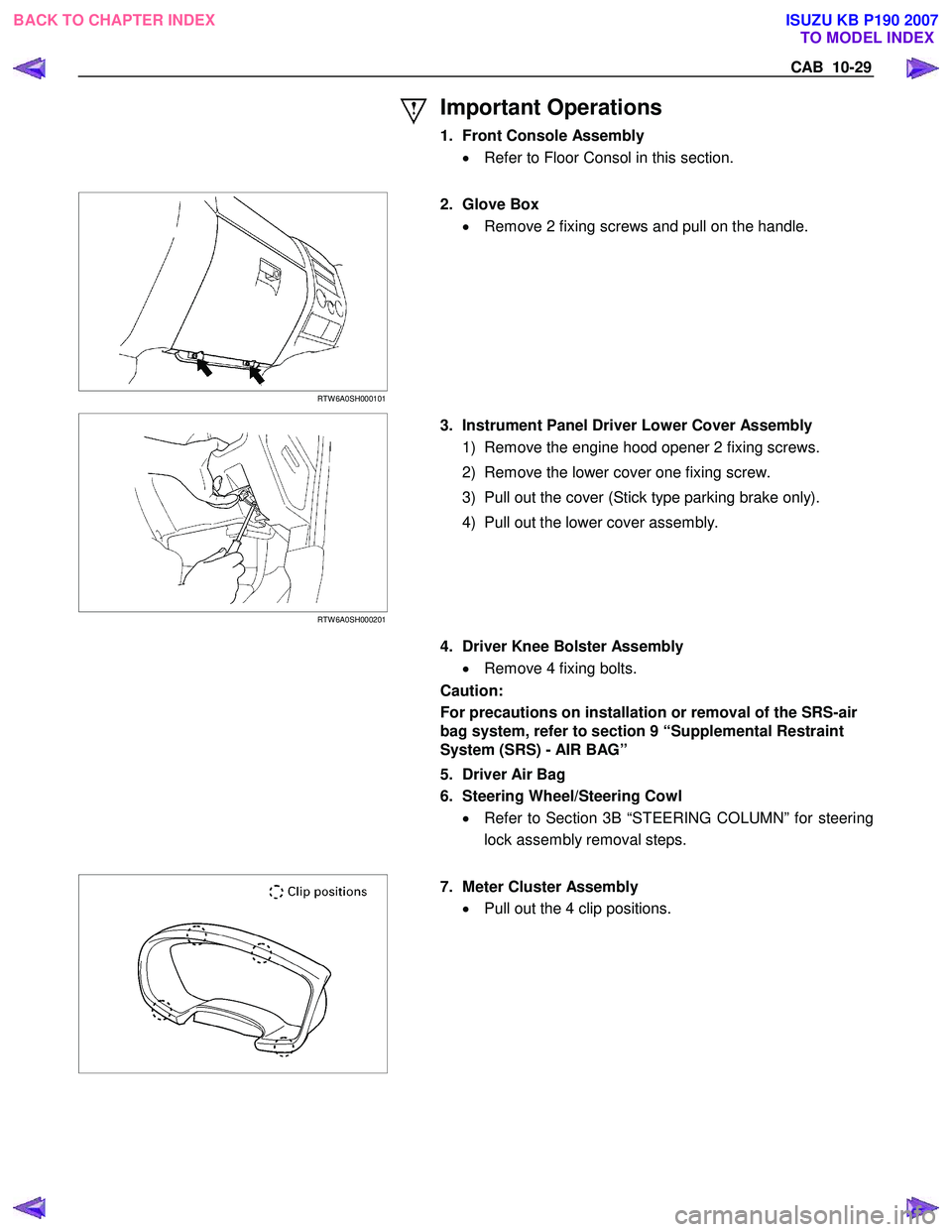
Important Operations
1. Front Console Assembly • Refer to Floor Consol in this section.
RTW 6A0SH000101
2. Glove Box
• Remove 2 fixing screws and pull on the handle.
RTW 6A0SH000201
3. Instrument Panel Driver Lower Cover Assembly
1) Remove the engine hood opener 2 fixing screws.
2) Remove the lower cover one fixing screw.
3) Pull out the cover (Stick type parking brake only).
4) Pull out the lower cover assembly.
4. Driver Knee Bolster Assembly
• Remove 4 fixing bolts.
Caution:
For precautions on installation or removal of the SRS-air
bag system, refer to section 9 “Supplemental Restraint
System (SRS) - AIR BAG”
5. Driver Air Bag
6. Steering Wheel/Steering Cowl • Refer to Section 3B “STEERING COLUMN” for steering
lock assembly removal steps.
7. Meter Cluster Assembly
• Pull out the 4 clip positions.
BACK TO CHAPTER INDEX TO MODEL INDEX
ISUZU KB P190 2007
Page 5788 of 6020
10-30 CAB
RUW 5A0SH002701
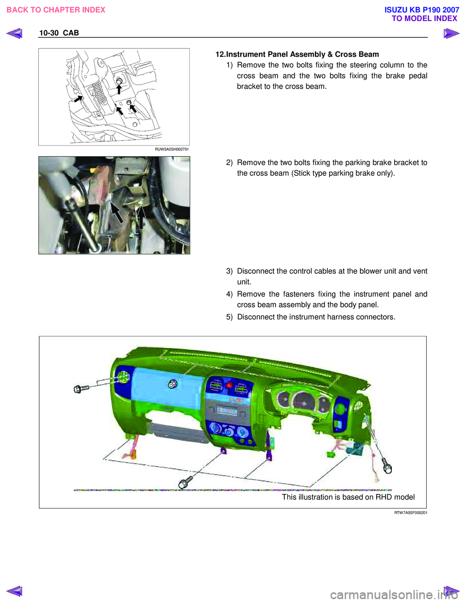
12. Instrument Panel Assembly & Cross Beam
1) Remove the two bolts fixing the steering column to the cross beam and the two bolts fixing the brake pedal
bracket to the cross beam.
2) Remove the two bolts fixing the parking brake bracket to
the cross beam (Stick type parking brake only).
3) Disconnect the control cables at the blower unit and vent
unit.
4) Remove the fasteners fixing the instrument panel and cross beam assembly and the body panel.
5) Disconnect the instrument harness connectors.
This illustration is based on RHD model
RTW 7A0SF000201
BACK TO CHAPTER INDEX TO MODEL INDEX
ISUZU KB P190 2007
Page 5789 of 6020
CAB 10-31
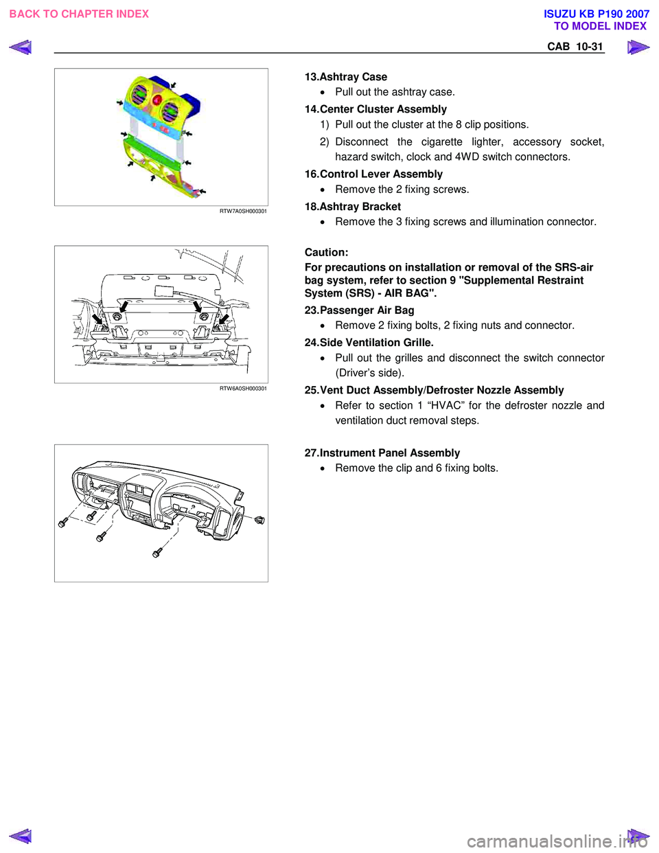
RTW 7A0SH000301
13.Ashtray Case
• Pull out the ashtray case.
14. Center Cluster Assembly 1) Pull out the cluster at the 8 clip positions.
2) Disconnect the cigarette lighter, accessory socket, hazard switch, clock and 4W D switch connectors.
16. Control Lever Assembly • Remove the 2 fixing screws.
18.Ashtray Bracket • Remove the 3 fixing screws and illumination connector.
RTW 6A0SH000301
Caution:
For precautions on installation or removal of the SRS-air
bag system, refer to section 9 "Supplemental Restraint
System (SRS) - AIR BAG".
23. Passenger Air Bag
• Remove 2 fixing bolts, 2 fixing nuts and connector.
24. Side Ventilation Grille. • Pull out the grilles and disconnect the switch connecto
r
(Driver’s side).
25. Vent Duct Assembly/Defroster Nozzle Assembly • Refer to section 1 “HVAC” for the defroster nozzle and
ventilation duct removal steps.
27. Instrument Panel Assembly
• Remove the clip and 6 fixing bolts.
BACK TO CHAPTER INDEX TO MODEL INDEX
ISUZU KB P190 2007
Page 5790 of 6020
10-32 CAB
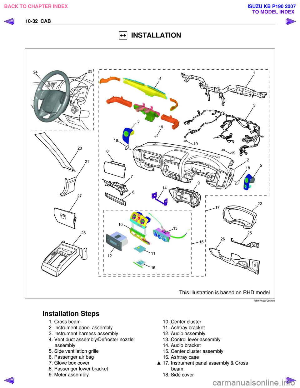
INSTALLATION
18 19
19 19
18
24 231
3
2
20
21
278
22
25
26
17
9
6
5
5
7
28
14
10
11
15
13
16
12
4
This illustration is based on RHD model RTW 7A0LF001401
Installation Steps
1. Cross beam
2. Instrument panel assembly
3. Instrument harness assembly
4. Vent duct assembly/Defroster nozzle assembly
5. Side ventilation grille
6. Passenger air bag
7. Glove box cover
8. Passenger lower bracket
9. Meter assembly
10. Center cluster
11. Ashtray bracket
12. Audio assembly
13. Control lever assembly
14. Audio bracket
15. Center cluster assembly
16. Ashtray case
▲ 17. Instrument panel assembly & Cross
beam
18. Side cover
BACK TO CHAPTER INDEX TO MODEL INDEX
ISUZU KB P190 2007
Trending: coolant temperature, Alternator, fuel additives, heating, oil level, ad blue, remote start
