JAGUAR X308 1998 2.G Workshop Manual
X308 1998 2.G
JAGUAR
JAGUAR
https://www.carmanualsonline.info/img/21/7640/w960_7640-0.png
JAGUAR X308 1998 2.G Workshop Manual
Trending: Amp, jacking, transmission fluid reservoir, battery capacity, handbrake, towing, remote start
Page 1901 of 2490
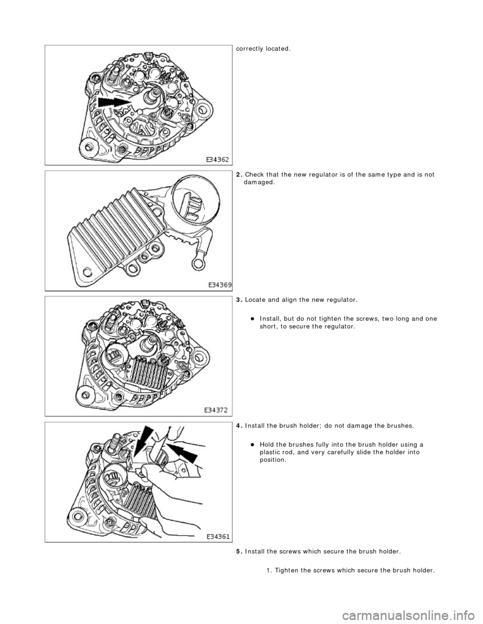
correctly located.
2. Check that the new regulator is of the same type and is not
damaged.
3. Locate and align the new regulator.
Install, but do not tighten the screws, two long and one
short, to secure the regulator.
4. Install the brush holder; do not damage the brushes.
Hold the brushes fully into the brush holder using a
plastic rod, and very carefully slide the holder into
position.
5. Install the screws which secure the brush holder.
1. Tighten the screws whic h secure the brush holder.
Page 1902 of 2490
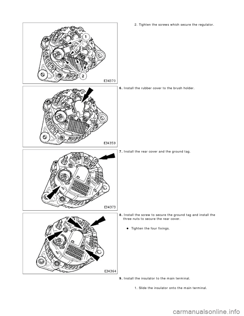
2. Tighten the screws which secure the regulator.
6. Install the rubber cover to the brush holder.
7. Install the rear cover and the ground tag.
8. Install the screw to secure th e ground tag and install the
three nuts to secure the rear cover.
Tighten the four fixings.
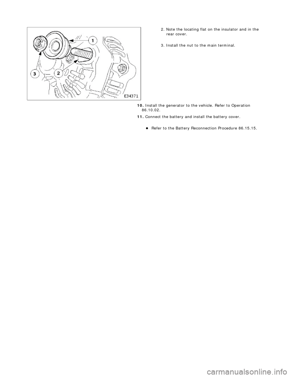
9. Install the insulator to the main terminal.
1. Slide the insulator on to the main terminal.
Page 1903 of 2490
2. Note the locating flat on the insulator and in the rear cover.
3. Install the nut to the main terminal.
10. Install the generator to the vehicle. Refer to Operation
86.10.02.
11. Connect the battery and in stall the battery cover.
Refer to the Battery Reconnection Procedure 86.15.15.
Page 1904 of 2490
Audio Unit - Audio System
Description and Operation
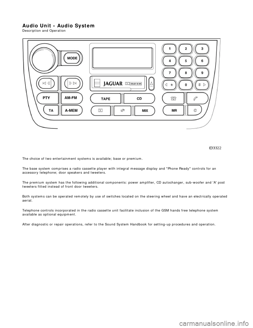
The choice of two entertainment system s is available; base or premium.
The base system comprises a radio cassette player with in tegral message display and "Phone Ready" controls for an
accessory telephone; door speakers and tweeters.
The premium system has the following additional components: power amplifier, CD autochanger, sub-woofer and 'A' post
tweeters fitted instead of front door tweeters.
Both systems can be operated remotely by use of switches loca ted on the steering wheel and have an electrically operated
aerial.
Telephone controls incorporated in the ra dio cassette unit facilitate inclusion of the GSM hands free telephone system
available as optional equipment.
After diagnostic or repair operations, refer to the Sound System Handbook for setting-up procedures and operation.
Page 1905 of 2490
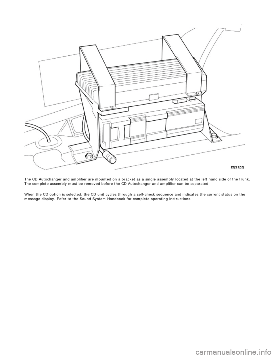
The CD Autochanger and amplifier are mounte d on a bracket as a single assembly located at the left hand side of the trunk.
The complete assembly must be removed before the CD Autochanger and amplifier can be separated.
When the CD option is selected, the CD unit cycles through a self-check sequence and indicates the current status on the
message display. Refer to the Sound System Ha ndbook for complete operating instructions.
Page 1906 of 2490
Audio Unit - Audio System
Diagnosis and Testing
Tests Using the Portable Diagnostic Unit
Refer to PDU User Guide
The PDU is unable to diagnose radio head, CD autochanger or amplifier faults; there are no self-diagnostics associated with
these components.
PDU is able to test the speakers and the antenna, along with associated wiring and connections, therefore by a process of
elimination, the other components can be diagnosed.
Page 1907 of 2490
Audio Unit - Capacitor
Removal and Installation
Removal
Installation
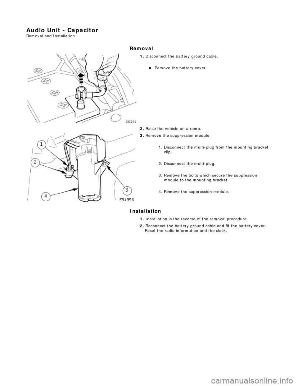
1. Disconnect the batt ery ground cable.
Remove the battery cover.
2. Raise the vehicle on a ramp.
3. Remove the suppr ession module.
1. Disconnect the multi-plug from the mounting bracket clip.
2. Disconnect the multi-plug.
3. Remove the bolts which secure the suppression module to the mounting bracket.
4. Remove the su ppression module.
1. Installation is th e reverse of the re moval procedure.
2. Reconnect the battery ground cable and fit the battery cover.
Reset the radio inform ation and the clock.
Page 1908 of 2490
Antenna - Antenna
Description and Operation
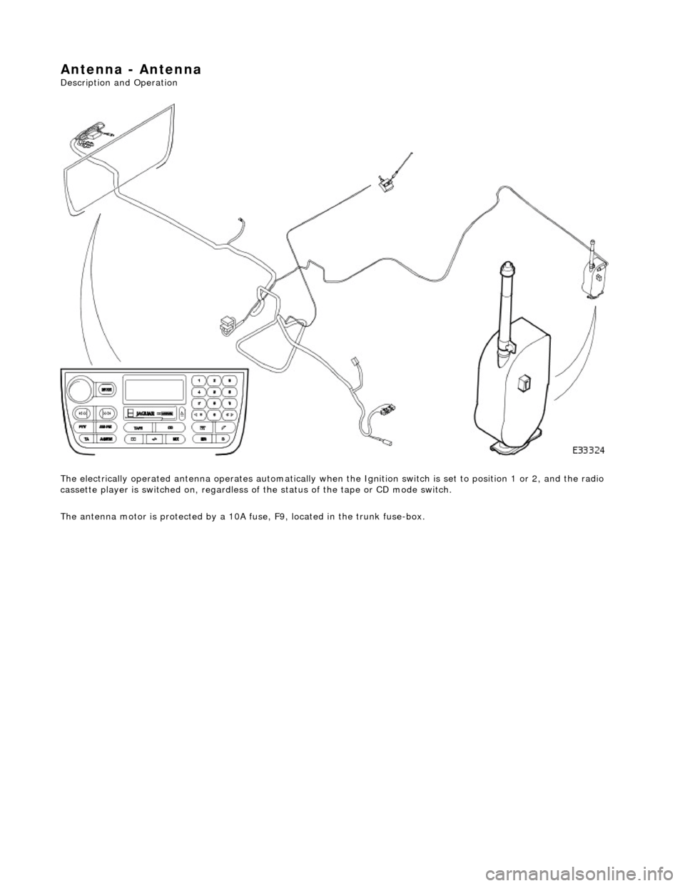
The electrically operated antenna operates automatically when the Ignition switch is set to position 1 or 2, and the radio
cassette player is switched on , regardless of the status of the tape or CD mode switch.
The antenna motor is protected by a 10A fuse, F9, located in the trunk fuse-box.
Page 1909 of 2490
Antenna - Antenna
Diagnosis and Testing
Tests Using the Portable Diagnostic Unit
Refer to PDU User Guide
The PDU tests whether or not the antenna raises and lowers correctly. Although it is obvious if the antenna is not operating,
the PDU analyses why it is not operating an d indicates problems such as a faulty radio head signal output, faulty wiring, loss of power due to a blown fuse.
Page 1910 of 2490
Speakers - Speakers
Description and Operation
Speaker Location
Parts List
ItemPart NumberDescription
1—Door Speaker
2—Front Door Tweeter (Base System)
3—Rear Door Tweeter
4—CD Autochanger (P remium System)
5—Amplifier (Premium System)
6—Sub-woofer (Premium System)
7—'A' Post Tweeter (Premium System)
Trending: aerial, seat motor fuse, Crankshaft sensor, 86.60.01, engine ignition, head lamp, Front absorber
