JAGUAR XFR 2010 1.G Workshop Manual
Manufacturer: JAGUAR, Model Year: 2010, Model line: XFR, Model: JAGUAR XFR 2010 1.GPages: 3039, PDF Size: 58.49 MB
Page 771 of 3039

Published: 11-May-2011
Steering Linkage - Steering Linkage - System Operation and Component Description
Description and Operation
TIE-ROD System Operation
The threads on the tie rods allow the position of the outer tie rod to be adjusted in order to set the correct toe angle for each
front wheel.
TIE-ROD Component Description
Each tie rod comprises two parts; an inner and outer tie rod. The inner and outer tie rods are screwed into each other and
locked with a locknut to prevent inadvertent movement.
The outer tie rod incorporates a non-serviceable tapered ball joint which locates in a tapered hole in the front wheel knuckle
and is secured with a self-locking nut. The ball joint has an internal hexagonal drive which enables the joint to be held
stationary when the self-locking nut is tightened.
Page 772 of 3039

Published: 11-May-2011
www.JagDocs.com
Page 773 of 3039
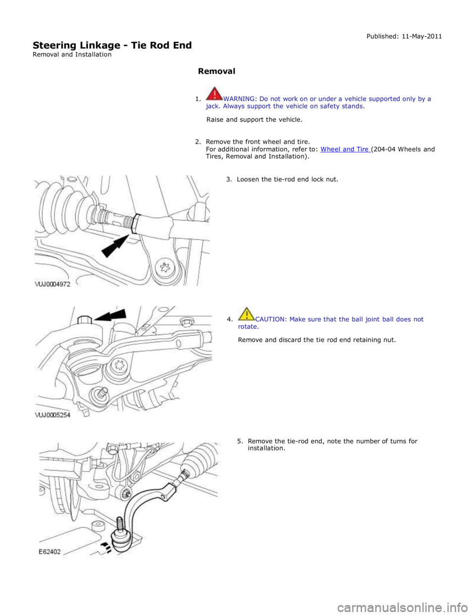
Tires, Removal and Installation).
3. Loosen the tie-rod end lock nut.
4. CAUTION: Make sure that the ball joint ball does not
rotate.
Remove and discard the tie rod end retaining nut.
5. Remove the tie-rod end, note the number of turns for
installation.
Page 774 of 3039
Installation
1. Install the tie rod end, note the number of turns until adjacent to the
locknut.
2. CAUTION: Make sure that the ball joint ball does not rotate.
Connect the tie-rod end ball joint.
Clean the component mating faces.
Install a new nut and tighten to 133 Nm.
3. Tighten the tie-rod locking nut.
Clean the component mating faces.
Tighten the nut to 55 Nm.
4. Install the front wheel.
For additional information, refer to: Wheel and Tire (204-04 Wheels and Tires, Removal and Installation).
5. Using only four-wheel alignment equipment approved by Jaguar, check
and adjust the wheel alignment.
For additional information, refer to: Four-Wheel Alignment (204-00 Suspension System - General Information, General Procedures).
Page 775 of 3039

Steering wheel retaining bolt 60 44 - Steering column pinch bolt 35 26 - Steering column retaining nuts 30* 22 - Tilt solenoid retaining bolts 1 - 9 Telescopic solenoid retaining bolts 1 - 9 Telescopic housing retaining bolts 8 - 71 If you are re-using this fixing on a vehicle built prior to VIN N83337, then tighten to 25 Nm. If you are replacing a fixing, then
you must tighten to 30 Nm.
Page 776 of 3039
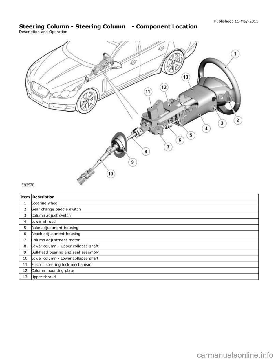
1 Steering wheel 2 Gear change paddle switch 3 Column adjust switch 4 Lower shroud 5 Rake adjustment housing 6 Reach adjustment housing 7 Column adjustment motor 8 Lower column - Upper collapse shaft 9 Bulkhead bearing and seal assembly 10 Lower column - Lower collapse shaft 11 Electric steering lock mechanism 12 Column mounting plate 13 Upper shroud
Page 777 of 3039

Steering Column - Steering Column - Overview
Description and Operation
OVERVIEW Published: 11-May-2011
The steering column comprises the upper column assembly, the lower column assembly and the steering wheel. The 3
components are positively connected together to pass driver rotary input from the steering wheel to a linear output of the
steering rack.
The upper column assembly contains electrical adjustment for steering wheel reach and rake, the electric steering lock
mechanism and the steering angle sensor. Steering adjustment memory positions are stored in the driver's seat module.
The electric steering column is a standard fitment on all models. The upper column assembly contains electrical adjustment for
steering wheel reach and rake, the electric column lock mechanism and the steering angle sensor. Steering adjustment memory
positions are stored in the driver's seat module. The column also features a 'tilt away' function which moves the steering
column away from the driver allowing easier exit and entry to the vehicle.
Column adjustment is provided by a single motor for both reach and rake adjustment. Operation of the column adjustment is
controlled by a four way joystick type switch located in the column lower shroud. Column adjustment is an integral part of the
driver position memory system.
www.JagDocs.com
Page 778 of 3039

Published: 20-May-2014
Steering Column - Steering Column - System Operation and Component Description
Description and Operation
Control Diagram
NOTE: A = Hardwired; D = High speed CAN bus; N = Medium speed CAN bus
Item Description 1 Battery 2 BJB (battery junction box) - Megafuse (175A) 3 RJB (rear junction box) 4 Electric steering column lock 5 High Speed CAN (controller area network) bus to other vehicle systems 6 CJB (central junction box)
Page 779 of 3039
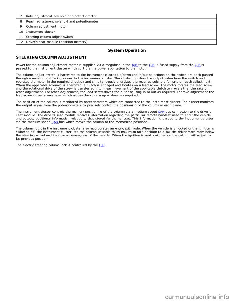
8 Reach adjustment solenoid and potentiometer 9 Column adjustment motor 10 Instrument cluster 11 Steering column adjust switch 12 Driver's seat module (position memory)
STEERING COLUMN ADJUSTMENT System Operation
Power for the column adjustment motor is supplied via a megafuse in the BJB to the CJB. A fused supply from the CJB is passed to the instrument cluster which controls the power application to the motor.
The column adjust switch is hardwired to the instrument cluster. Up/down and in/out selections on the switch are each passed
through a resistor of differing values to the instrument cluster. The cluster monitors the output value from the switch and
operates the motor in the required direction and simultaneously energizes the required solenoid for rake or reach adjustment.
When the applicable solenoid is energized, a clutch is engaged and locates on a lead screw. The motor rotates the lead screw
and the rotational drive of the screw is transferred into linear movement of the applicable clutch to move either the rake or
reach adjustment. For reach adjustment, the lead screw drives the outer housing in or out as required. For rake adjustment the
lead screw drives a rake lever which moves the column up or down as required.
The position of the column is monitored by potentiometers which are connected to the instrument cluster. The cluster monitors
the output signal from the potentiometers to precisely control the positioning of the column in each plane.
The instrument cluster controls the memory positioning of the column via a medium speed CAN bus connection to the driver's seat module. The driver's seat module receives information regarding the particular remote handset used to enter the vehicle
and outputs positional information relative to that stored for the handset. This information is passed to the instrument cluster
via the medium speed CAN bus which moves the column to the memorized positions.
The column logic in the instrument cluster also incorporates an entry/exit mode. When the vehicle is unlocked or the ignition is
switched off, the instrument cluster lifts the column upwards to its maximum rake position to allow the driver more room below
the steering wheel and improve access/egress of the vehicle. When the ignition is next switched on the column will adjust to
its previous position.
The electric steering column lock is controlled by the CJB.
Page 780 of 3039
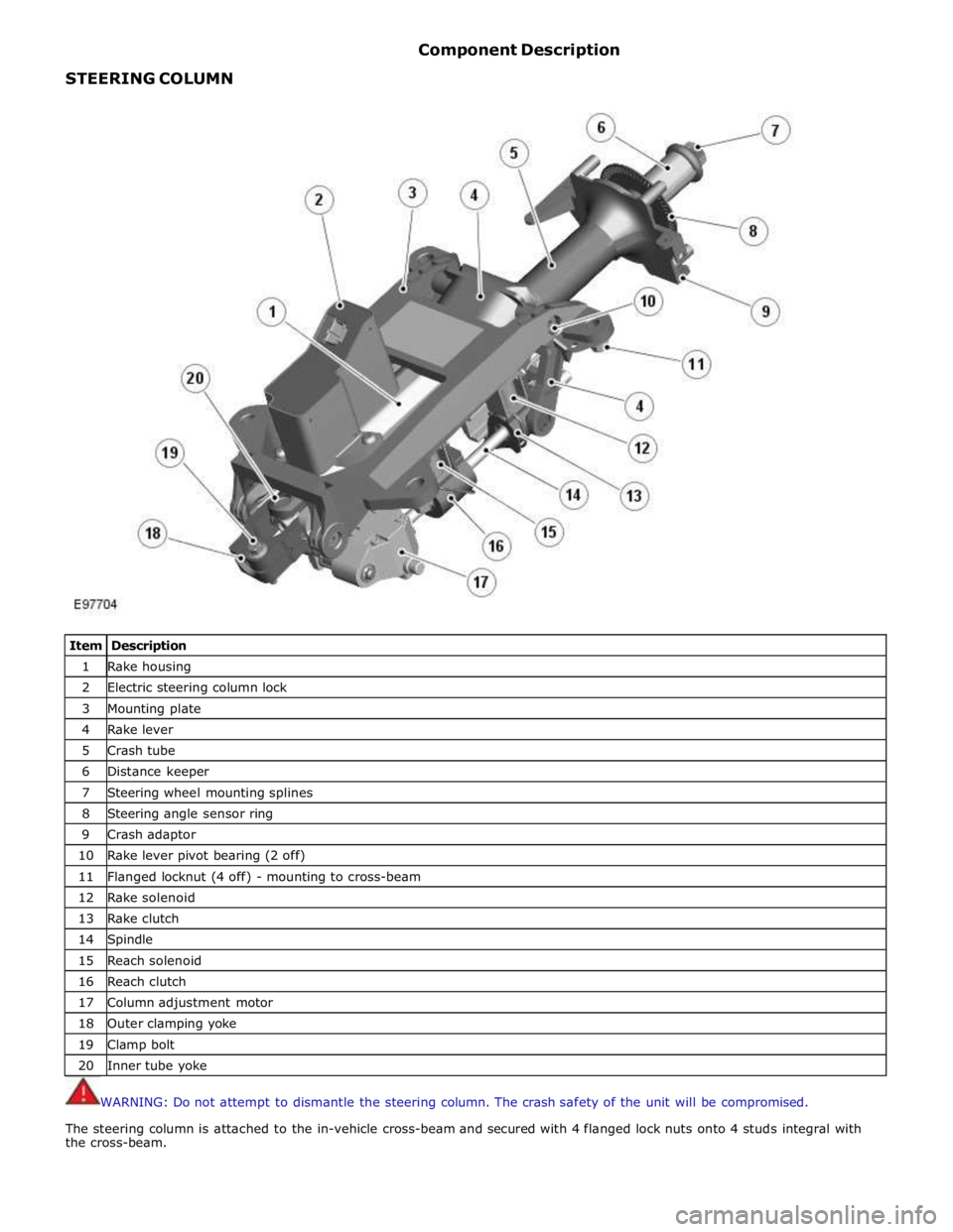
STEERING COLUMN Component Description
Item Description 1 Rake housing 2 Electric steering column lock 3 Mounting plate 4 Rake lever 5 Crash tube 6 Distance keeper 7 Steering wheel mounting splines 8 Steering angle sensor ring 9 Crash adaptor 10 Rake lever pivot bearing (2 off) 11 Flanged locknut (4 off) - mounting to cross-beam 12 Rake solenoid 13 Rake clutch 14 Spindle 15 Reach solenoid 16 Reach clutch 17 Column adjustment motor 18 Outer clamping yoke 19 Clamp bolt 20 Inner tube yoke
WARNING: Do not attempt to dismantle the steering column. The crash safety of the unit will be compromised.
The steering column is attached to the in-vehicle cross-beam and secured with 4 flanged lock nuts onto 4 studs integral with
the cross-beam.