LAND ROVER FRELANDER 2 2006 Repair Manual
Manufacturer: LAND ROVER, Model Year: 2006, Model line: FRELANDER 2, Model: LAND ROVER FRELANDER 2 2006Pages: 3229, PDF Size: 78.5 MB
Page 291 of 3229
Publi s hed: 11-May-2011
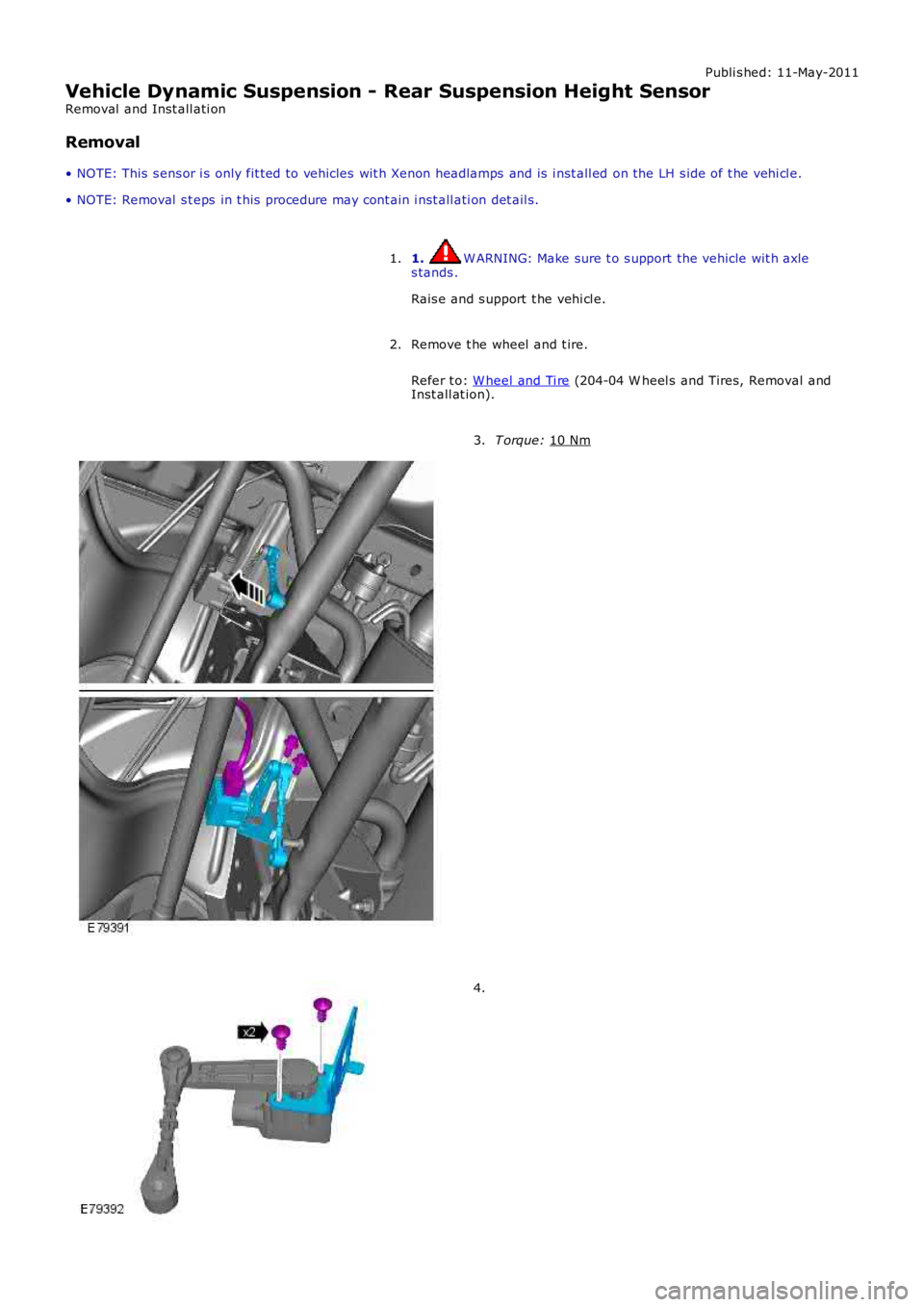
Vehicle Dynamic Suspension - Rear Suspension Height Sensor
Removal and Inst all ati on
Removal
• NOTE: This s ens or i s only fit ted to vehicles wit h Xenon headlamps and is i nst all ed on the LH s ide of t he vehi cl e.
• NOTE: Removal s t eps in t his procedure may cont ain i nst all ati on det ail s.
1. W ARNING: Make sure t o s upport the vehicle wit h axle
s tands .
Rais e and s upport t he vehi cl e.
1.
Remove t he wheel and t ire.
Refer t o: W heel and Ti re (204-04 W heel s and Tires, Removal and
Inst all at ion).
2. T orque:
10 Nm 3.
4.
Page 292 of 3229

Installation
To i nst all , revers e t he removal procedure.1.
Us ing Land Rover approved di agnos ti c equi pment , calibrate t hes ensor.2.
Page 293 of 3229
Publi s hed: 11-May-2011
Ride and Handling Optimization - Ride and Handling Optimization
Des cript ion and Operat ion
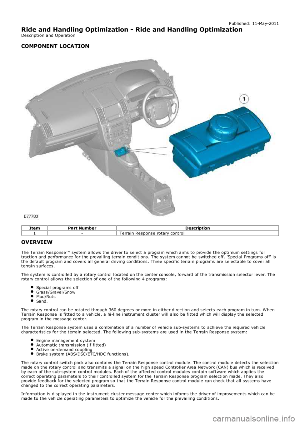
COMPONENT LOCATION
ItemPart NumberDescription
1-Terrain Res pons e rotary cont rol
OVERVIEW
The Terrai n Res pons e™ sys tem all ows the driver t o s el ect a program which aims t o provide t he opti mum set ti ngs fort racti on and performance for t he prevai li ng terrai n condit ions . The s ys t em cannot be swi tched off. 'Speci al Programs off' ist he default program and covers all general drivi ng condit ions . Three s peci fi c terrain programs are s electable to cover allt errai n s urfaces .
The s ys t em i s cont rol led by a rot ary control l ocat ed on t he cent er cons ol e, forward of t he transmis s ion s elector lever. Therot ary control al lows t he s electi on of one of the followi ng 4 programs :
Speci al programs offGras s /Gravel /SnowMud/Rut sSand.
The rot ary control can be rot at ed t hrough 360 degrees or more in ei ther direct ion and s elects each program i n t urn. W henTerrai n Res pons e i s fi tt ed t o a vehicle, a hi -l ine i nst rument clus t er wi ll als o be fi tt ed which wi ll dis play t he s electedprogram in the mess age cent er.
The Terrai n Res pons e s ys tem uses a combi nat ion of a number of vehicle s ub-s ys tems to achieve t he required vehi cl echaract eri st ics for the t errain s elected. The fol lowi ng s ub-s ys t ems are us ed i n t he Terrai n Res pons e s yst em:
Engi ne management s ys temAutomat ic t rans mi ss ion (i f fi tt ed)Acti ve on-demand coupli ngBrake s ys tem (ABS/DSC/ETC/HDC funct ions ).
The rot ary control swi tch pack als o contai ns the Terrain Res ponse cont rol module. The cont rol module det ect s t he s el ect ionmade on t he rot ary cont rol and transmit s a s ignal on the hi gh s peed Cont rol ler Area Net work (CAN) bus which i s receivedby each of the s ub-s ys tem cont rol modules . Each of t he affect ed cont rol modules contai n s oft ware whi ch appl ies t hecorrect operati ng paramet ers t o t hei r cont rol led s yst em for the Terrai n Respons e program s electi on made. They als oprovide feedback for t he s elected program s o that the Terrai n Respons e cont rol module can check that all s yst ems havechanged t o t he correct operati ng paramet ers .
Informat ion i s dis played i n the ins trument cl us t er mess age center which i nforms the driver of improvement s which can bemade t o t he vehi cl e operat ing paramet ers t o opt imi ze the vehicle for t he prevaili ng condi ti ons .
Page 294 of 3229
Inexperi enced off-road dri vers may benefi t from t he automat ic as s is tance of t he Terrai n Respons e s yst em and t he driverinformat ion. Experienced off-road drivers can s elect the specific programs for ext reme condit ions t o acces s cont rol over t hevehi cl e s yst ems (for example; accel erator pedal maps , t rans mis s ion s hift maps , traction s ett ings ) which are not access i bl eon vehicles wi thout Terrai n Res pons e.
Stop/St art Vehicl es - From 2010 MY
Acti vat ion of t he Terrai n Res pons e s peci al programs wi ll deact ivate the St op/St art syst em.
However, if Terrain Res pons e is acti vat ed when t he engi ne is shut down in a Stop/St art cycl e t he engi ne wil l aut omat ical lyres t art . If duri ng thi s event t he Stop/Start sys tem cannot detect the driver's occupancy, for example ei ther t he dri ver’ss afety bel t or door i s unlatched, the engine wi ll not res t art . The St op/St art s yst em will reques t t he driver t o depres s theclutch t o rest art t he engine. The dri ver wi ll be i nformed of t his by ‘RESTART REQUIRED PRESS CLUTCH’ being di spl ayed i nt he mes sage center.For addit ional informat ion, refer t o: Starti ng Sys t em (303-06C Starti ng Syst em - TD4 2.2L Di es el, Vehicles Bui lt From:01-03-2009, Descripti on and Operat ion).
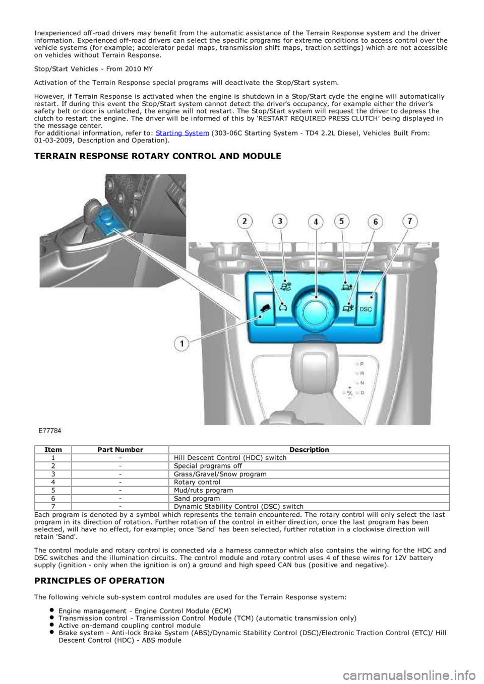
TERRAIN RESPONSE ROTARY CONTROL AND MODULE
ItemPart NumberDescription1-Hil l Des cent Cont rol (HDC) s wi tch
2-Special programs off
3-Gras s /Gravel/Snow program4-Rot ary cont rol
5-Mud/rut s program
6-Sand program7-Dynami c Stabil it y Control (DSC) s wit ch
Each program is denoted by a s ymbol whi ch repres ent s t he t errai n encountered. The rotary cont rol wi ll only s elect the las tprogram in it s direct ion of rotat ion. Further rot ati on of the control in ei ther direct ion, once the l ast program has beens elect ed, wil l have no effect, for exampl e; once 'Sand' has been s elect ed, furt her rotat ion i n a clockwis e direct ion wil lret ain 'Sand'.
The cont rol module and rot ary cont rol i s connected vi a a harnes s connector which al so cont ains t he wiring for the HDC andDSC s wit ches and the i ll uminati on circuit s . The cont rol module and rotary cont rol uses 4 of t hes e wi res for 12V bat t erys uppl y (i gnit ion - only when the i gni ti on is on) a ground and high s peed CAN bus (pos i ti ve and negat ive).
PRINCIPLES OF OPERATION
The fol lowing vehicl e s ub-s ys t em control modul es are us ed for t he Terrain Res pons e sys tem:
Engi ne management - Engine Cont rol Module (ECM)Trans mis s ion control - Transmis s ion Control Modul e (TCM) (automat ic t rans mi ss ion only)Acti ve on-demand coupli ng cont rol moduleBrake s ys tem - Anti -l ock Brake Sys t em (ABS)/Dynami c Stabil it y Control (DSC)/Electroni c Tracti on Control (ETC)/ Hi llDes cent Control (HDC) - ABS module
Page 295 of 3229
Each sub-sys tem operates in di fferent ways in relati on t o t he sel ect ed Terrai n Res pons e program t o achieve t he opt imumt racti on, s t abi lit y and eas e of cont rol for t he t errai n encount ered.
Engine Management System (EMS)
The EMS can change t he accel erator pedal maps to change the amount of t orque per percent age of pedal travel .
Each terrain program uses a combi nat ion of operat ing paramet ers for each sub-sys tem. Changing bet ween terrain programsini ti at es a di fferent s et of operat ing characteris ti cs which wil l be noti ceable to the driver, for example; i f the accel erat orpedal i s held i n a const ant pos i ti on and the terrain program is changed from Gras s /Gravel /Snow t o Sand, the driver wil lnoti ce the t orque and engine s peed increas e. If t he t errai n program is changed from Sand t o Grass /Gravel/Snow, t he dri verwil l not ice a reduct ion in t orque and engine s peed.
• NOTE: The change i n t orque and engine s peed can take approximat ely 30 s econds and care mus t be taken not to confus et he Terrai n Respons e s yst em operat ion wit h an EMS faul t.
Transmission Control (Automatic transmission only)
The t ransmis s ion control modul e changes t he shi ft maps for the Terrain Respons e program s elect ed. Thi s changes t he s hi ftpoints providing early or l at e ups hift s and downs hi ft s .
For example, i n t he Gras s /Gravel /Snow program, the trans mi ss i on wil l perform early ups hi ft s and very late downs hifts toensure t he transmis si on is in t he highes t gear pos si ble. The hil l det ect ion funct ion of t he Trans mis s ion Cont rol module(TCM) will l ock t he t orque converter and hold whi chever gear i s s el ect ed t o t he engine s peed (RPM) li mit i f neces s ary whendescending a s t eep incli ne. This provi des maximum engi ne braking before t he dri ver needs t o appl y t he brakes.
Sport mode i s only avail abl e when t he general program i s s elected. Sport mode i s disabled i n all Terrain Res pons e s peci alprograms. 'CommandShift ™' is avail abl e in any program.
Active On-Demand Coup ling Control
The act ive on-demand coupli ng cont rol module has 2 operati ng s trat egies ; pre-empt ive and react ive.
The pre-empti ve st rat egy anti ci pat es and predict s the locki ng torque val ue required t o mi ni mi ze sl ip and maxi mizes tabil it y. Each Terrain Res pons e program has a different t hres hol d and i nput cri teria for the pre-empt ive s t rategy. Forexampl e, a higher locki ng t orque would be appl ied on s li ppery s urfaces .
The reacti ve s trategy vari es the amount of locking t orque in res pons e t o t he actual s lip level and t he dynamic behavi or oft he vehi cl e. Each Terrain Res pons e program has a different t hres hol d and input for the react ive s trategy. The reacti ves trategy i mproves vehi cl e t racti on and compos ure by eliminati ng any wheel s pin which has occurred aft er the pre-empt ives trategy was appli ed. The l ocking res pons e appli ed is appli cable to the t errain program sel ect ed. For exampl e, verys ens i ti ve on s lippery surfaces to provide maximum t racti on and mi nimi ze surface damage.
The locking t orque calculati ons use various s ignals from other s ub-s yst ems , for example, engi ne torque, accel erator pedalposi ti on, s elect ed gear, st eeri ng angl e, vehicle s peed, lat eral accelerat ion, yaw behavi or.
The DSC funct ion of t he ABS s ys t em can override t he act ive on-demand coupli ng cont rol and reduce any appl ied l ocki ngt orque during DSC act ion.
ABS System Control
The ABS module cont rols several functi ons and adjust s t he operati ng paramet ers of t hes e funct ions t o opti mize thes elect ed Terrain Res pons e program.
Tracti on Control
Tracti on cont rol us es different s li p/accel erati on thresholds to i mprove t ract ion and vehicle compos ure. For example, t hes ys t em s ens it ivit y is increased on s lippery surfaces s uch as wet grass or s now t o reduce wheel s pi n. If wheel s pi n wasall owed in t hese ci rcums tances, l oss of t ract ion may res ul t from surface damage (wet grass ) or t he car being unable tomove (snow) due t o wheel spi n.
Dynamic St abi li ty Cont rol
If DSC is s wi tched off (wit h t he DSC s wi tch adjacent to t he Terrain Res pons e rotary cont rol ) when usi ng a TerrainRespons e s peci al program, if t he s peci al program i s s ubs equent ly changed for a di fferent program, DSC is aut omat icall ys wit ched back on.
The DSC us es different t hres hol d values for t he s elected program t o aut omati call y reduce DSC i ntervent ion, removing t herequirement for t he dri ver t o dis able t he DSC s ys tem in order to reduce engine intervent ion whi ch is s omet imes i nduced i nextreme off-road condi ti ons . In ext reme s and condit ions , there may be an addit ional benefit of dis abling the DSC funct ionus ing t he DSC s wit ch in addi ti on to sel ect ing t he s and program.
In the Mud/Ruts program the DSC sys tem is cal ibrat ed t o tol erate a higher 'yaw' thres hold. This al lows a greaterdifferent ial between t he actual and des i red wheel turni ng behavi or before DSC i ntervenes . Thi s all ows the DSC s ys t em t oignore the effect of rut s 'jarring' t he car or adjust ing t he front wheel s t eering angle.
The Terrai n Res pons e s ys tem can al ter t he balance bet ween engine and brake i ntervention. For example, when t he s andprogram is sel ect ed, t he DSC s ys tem reduces it s rel iance on engi ne int erventi on and increas es the us e of brakeint erventi on to maint ai n t he vehi cl es momentum and prevent it from becomi ng bogged down i f wheel s li p i s detected.
Hil l Descent Cont rol
HDC i s automat icall y s wit ched on or off and target s peeds are adjus t ed in res pons e to t he Terrai n Res pons e programs elect ed. The res pons iveness of the HDC functi on is al so increas ed where requi red.
Automat ic operat ion of HDC ai ms t o as s is t the driver by s wit chi ng t he sys t em on or off when it is of most benefi t. HDC isonly aut omat icall y s wit ched on when the mud/rut s program i s s elect ed. HDC i s not automati cal ly s elected in ot her
Page 296 of 3229
programs.
Incorrect Program Usage
Selecti on of an inappropri at e program i s dis couraged in t he followi ng ways:
The act ive program icon is conti nual ly di spl ayed i n t he ins t rument clus ter mes s age centerThe Terrai n Res pons e control modul e 'l ocks ' out cert ain funct ions i n s ome programs, for exampl e:- cruis e control is only avai lable wi th the special programs off or gras s/gravel/s now program- t rans mis s ion 'Sport' mode i s deact ivated i n all s peci al programs .W hen t he i gni ti on has been in t he off mode, cont inuall y for more t han 6 hours , t he Terrai n Respons e s yst emdefault s t o t he special programs off.
Selecti on of an inappropri at e program for the t errain condit ions wil l not endanger the dri ver or cause damage to thevehi cl e. Cont inued us e of an inappropri ate program may reduce t he li fe of s ome component s . The driver may not icereduced vehi cl e res ponse, wi th the engine and t rans mi ss i on bei ng les s respons ive t han in s peci al programs off. Al so, i ns ome programs, HDC wil l remai n on, si gni fi ed by il lumi nat ion of t he HDC indicator in the i nst rument clus t er. The dri ver mayals o not ice t orque 'wi nd-up' i n t he act ive on-demand coupli ng caus ing a braking effect when the vehicl e is manoeuvred i ns ome s peci al programs .
Driver Information
The high-l ine i nst rument clus t er fit t ed to al l vehi cl es wit h Terrain Res pons e, cont ains a mess age center which di spl aysvehi cl e i nformat ion to t he driver. The mes s age cent er contai ns the Terrain Res ponse program icons which dis play t hecurrent ly s elected program. If no s ymbol i s dis played, no special program is sel ect ed and the sys tem is in 'Specialprograms off'.
Any required changes t o t he s ub-s ys t ems are al s o pass ed t o t he dri ver i n t he form of i ndi cat or ill uminat ion i n t heins t rument clus ter or appropriat e mes s ages i n t he mes s age center, 'HDC OFF' for example.
In certai n operati ng condi ti ons , t he Terrai n Res pons e s yst em al s o dis plays advi ce or warning mess ages to ens ure thedri ver i s us ing t he vehi cl e t o it s full potenti al, for example, s t eering angle is dis played i n t he mes sage center t o avoi ddri vi ng in deep rut s wit h s t eering l ock appli ed.
DIAGNOSTICS
The Terrai n Res pons e control modul e s tores informati on on detect ed Terrai n Respons e faul ts and CAN errors whi ch can beint errogat ed usi ng IDS. The Terrain Res ponse s ub-s ys t ems and t he ins trument cl ust er als o s tore informat ion relat ing t oCAN errors from t he Terrain Res pons e control modul e.
The cont rol module al s o s tores the mil es travel ed and ti me el aps ed for t he i ndi vi dual programs which can al so be ret ri evedus ing IDS. Thi s informat ion aids di agnos is of t he Terrain Res pons e s ys tem and als o provi des an indicati on of Terrai nRespons e s yst em abus e by t he dri ver whi ch can l ead to premat ure component failure.
This i nformat ion can al so be us ed to check cus t omer concerns , for exampl e, hi gh fuel cons umpt ion whi ch may be due t ocont inued us e of a cert ain program.
Terrain Response System Fault Diag nosis
Terrai n Res pons e relies on the correct funct ionali ty of t he 4 s ub-s ys tems . If one of the s ub-s ys tems develops a fault , theTerrai n Res pons e s ys tem wil l not funct ion, even though the fault i s NOT in t he Terrain Res pons e s ys tem.
T he T errain Response control module and rotary control should only be investigated if there are no apparent faultsin any of the sub-systems. If a fault in a sub-system is subsequently corrected, the T errain Response system willfunction normally after an ignition mode 1 and 2 (on and off) cycle.
Terrain Response Sub-System Faults
W hen a fault occurs i n a s ub-s yst em, t he dri ver i s alert ed by t he il lumi nat ion of a warning indicator and/or an appropri atemes s age for that s ub-s yst em in t he i ns t rument clus ter mes s age cent er. There wi ll be no warning of a Terrain Res ponses ys t em fault .
W hen a sub-sys t em faul t is present and t he dri ver at tempt s t o s el ect a different Terrain Res pons e program us i ng therot ary control or at t he next ignit ion mode 2 (on) cycl e, a mes sage 'SY STEM FAULT SPECIAL PROGRAMS NOT AVAILABLE'wil l appear in the mess age cent er. This impl ies t hat t he Terrain Res pons e s ys tem has a faul t, but only because asub-system fault is preventing its operation. Thi s mes sage will be di spl ayed for 5 s econds per ignit ion mode 2 cycl e, butis repeat ed i f a further s electi on is made by the driver usi ng t he Terrai n Respons e rot ary control or at t he next ignit ionmode 2 (on) cycle.
• NOTE: The mes s age 'SY STEM FAULT SPECIAL PRO GRAMS NOT AVAILABLE' can al so be generated by a fault i n t he Terrai nRespons e rot ary control or control modul e. Refer to the foll owing i nformat ion for det ail s of rot ary control or control modul efaul ts .
It is not possible for the T errain R esponse control module to cause any fault behavior (w arning indicator illuminationor message generation) in any of the 4 sub-systems. Illuminati on of a s ub-s ys t em warning i ndi cat or and/or as ub-s ys t em relat ed mes sage wi ll NEVER be ass ociated wit h a Terrain Res ponse cont rol module or Terrain Res pons es ys t em fault .
The s ub-s ys t em control modul es can det ect a fault wit h the CAN s ignal from t he Terrai n Res pons e control modul e. If afaul t in t he Terrain Res pons e s ys tem is det ect ed, the s ub-s ys tem cont rol modules wi ll operate in t he 'Special programs off's ett ing. The s ub-s ys t em control modul es wil l record a fault code for a fail ure of t he Terrai n Res pons e CAN si gnal . Thes efaul ts can be retrieved us ing IDS and wi ll provide us eful informat ion t o i ndi cat e i nves ti gat ion of t he Terrain Res pons econt rol module or t he CAN net work.
Terrain Response Rotary Control or Control Module Fault
Page 297 of 3229
If a fault occurs i n t he Terrai n Res pons e rot ary cont rol, al l rotary cont rol i con amber Light Emi tt ing Di odes (LED's ) wil l bet urned off and rotat ion of t he rot ary control i s ignored. The i ns t rument clus ter mess age cent er will di spl ay a mes s age'SY STEM FAULT SPECIAL PROGRAMS NOT AVAILABLE' when t he fault occurs , if t he fault i s pres ent and the driver att emptst o s el ect a s pecial program (if t he cont rol module is able to do thi s) or at t he next i gni ti on mode 2 (on) cycle.
The Terrai n Res pons e rotary cont rol and t he cont rol module are an i nt egral unit . If a fault occurs in eit her component , thewhole uni t wil l requi re replacement. ENSURE T HAT T HE FAULT IS WIT H T HE T ERRAIN RESPONSE CO NT ROL MO DULEAND NOT IN A SUB-SYST EM MODULE BEFO RE REPLACING T HE MODULE.
If a CAN faul t exi s ts and prevent s Terrai n Res pons e s yst em operat ion, all of t he Terrai n Res pons e rotary cont rol icon LED'swil l be il lumi nat ed and rot ati on of the rot ary cont rol i s ignored.
If the i nst rument clus ter does not receive a Terrain Res ponse s ys t em CAN mess age from the Terrain Res ponse cont rolmodule, t he mes sage 'SY STEM FAULT SPECIAL PROGRAMS NO T AVAILABLE' wi ll be dis played when t he faul t occurs and willbe repeat ed at every ignit ion mode 2 (on) cycl e.
User Error
The fol lowing incorrect us age of t he s yst em may be mi si nterpreted as a s ys t em fault :
Engi ne not running - Program changes and driver advi s ory mes s ages are only avail abl e wi th the engine runni ngSpeci al program change att empted wi th DSC or ABS acti ve (t his i ncl udes ABS cycling which is operat ional when HDCis bei ng used on s lippery or l oose surfaces)Speci al program change att empted wi th overheat condi ti on pres ent on the act ive on-demand coupling.
Page 298 of 3229
Publi s hed: 11-May-2011
Ride and Handling Optimization - Ride and Handling Optimization
Diagnosi s and Tes ti ng
Principles of Operation
For a detail ed descripti on of the Terrain Respons e s ys t em, refer t o t he rel evant Descript ion and Operat ion secti on in theworks hop manual .REFER to: Ri de and Handl ing Opt imi zat ion (204-06 Ri de and Handl ing Opt imizati on, Des cript ion and Operat ion).
Inspection and Verification
CAUTION: Di agnos is by s ubs ti tut ion from a donor vehicle is NO T acceptabl e. Subs ti tut ion of cont rol modules doesnot guarant ee confirmat ion of a faul t, and may als o caus e addit ional fault s i n t he vehi cl e being t est ed and/or t he donorvehi cl e.
1. Verify t he cus t omer concern.1.
2. Vis ually ins pect for obvious s igns of mechani cal or electrical damage.2.
Visual InspectionMechanicalElectrical
* Ti re condit ion, pres sures, et cDriveline, Engine, Transmis s ion, Sus pensi on,component s (correct ins tall ati on, damage, etc)
Fus esHarness es /Connect orsTerrai n res pons e modul eEngi ne Cont rol Module (ECM)Transmis s ion Control Modul e (TCM)Ant i-Lock Brake Sys t em control modul eAct ive On-demand cont rol moduleDynami c s us pensi on cont rol module * Controllerarea network (CAN) ci rcuit s
3. If an obvious cause for an obs erved or report ed concern is found, correct t he caus e (if pos s ible) beforeproceeding t o t he next s t ep.3.
4. If t he caus e is not vis ually evi dent , check for Di agnos ti c Trouble Codes (DTCs) and refer t o t he DTC Index.4.
DTC Index
• NOTE: If the control modul e/t rans mis s ion i s s uspect and the vehicle remai ns under manufacturer warrant y, refer t o t heW arranty Pol icy and Procedures manual (s ect ion B1.2), or determine i f any pri or approval programme is in operat ion, pri ort o the ins tall ati on of a new module/transmis s ion.
• NOTE: Generic scan t ool s may not read the codes li st ed, or may read only fi ve digit codes . Mat ch the five di git s from t hes can tool to the firs t fi ve di git s of the seven digi t code l is ted to ident ify t he faul t (t he las t t wo digi ts gi ve addi ti onalinformat ion read by the manufact urer approved diagnos t ic s ys tem).
• NOTE: W hen performing el ect ri cal volt age or resi s tance tes t s, al ways us e a digit al mult imet er (DMM) accurate to threedeci mal places , and wi th an up-to-date cali brat ion cert ificate. W hen t es ti ng res is t ance, always take t he res i st ance of t heDMM leads int o account.
• NOTE: Check and recti fy bas ic faul ts before beginni ng diagnos t ic rout ines i nvol vi ng pinpoint t es t s.
• NOTE: Ins pect connect ors for s igns of water ingres s , and pins for damage and/or corros ion.
• NOTE: If DTCs are recorded and, aft er performi ng the pi npoi nt tes ts , a fault is not present , an int ermi tt ent concern maybe t he caus e. Always check for loose connect ions and corroded terminals .
For a compl ete lis t of all Di agnos ti c Trouble Codes (DTCs) t hat could be logged on this vehicle, pleas e refer to Sect ion100-00.
REFER to: Di agnos ti c Trouble Code (DTC) Index - DTC: Terrain Res pons e Cont rol Modul e (ATCM) (100-00 GeneralInformat ion, Des cript ion and Operat ion).
Page 299 of 3229
Publi s hed: 11-May-2011
Ride and Handling Optimization - Ride and Handling Optimization Switch
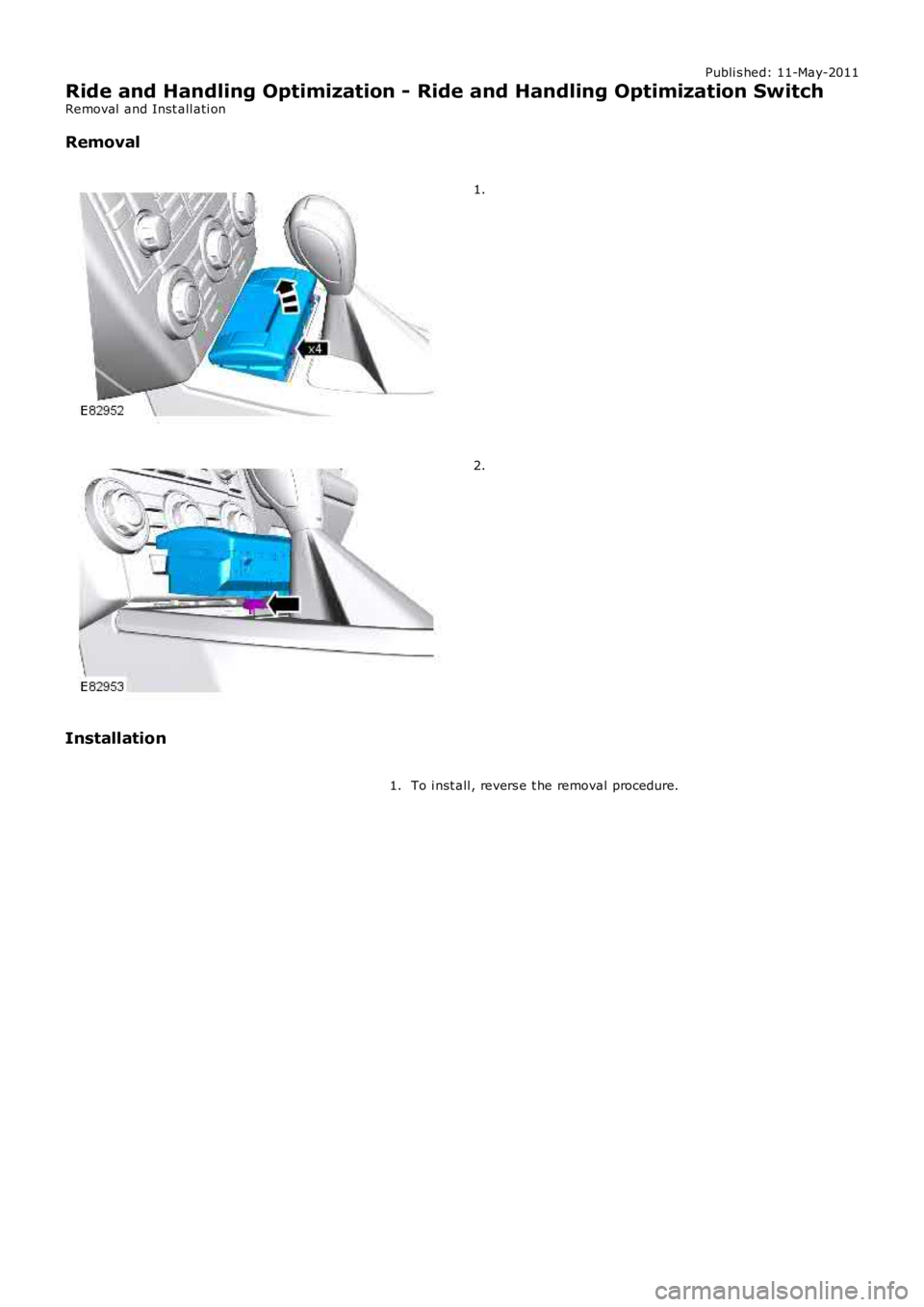
Removal and Inst all ati on
Removal
1.
2.
Installation
To i nst all , revers e t he removal procedure.1.
Page 300 of 3229
Publi s hed: 11-May-2011
Driveline System - General Information - Driveline System
Diagnosi s and Tes ti ng
Principles of Operation
For a detail ed descripti on of the driveli ne s ys t ems , refer t o t he rel evant Des cript ion and Operat ion s ecti on in the works hopmanual. REFER to:
Dri ves haft (205-01 Driveshaft , Des cript ion and Operat ion),Univers al Joint s (205-01 Dri ves haft , Descripti on and Operat ion),Rear Drive Axle and Different ial (205-02 Rear Drive Axle/Different ial, Des cri pt ion and Operati on),Front Dri ve Axl e and Di fferenti al (205-03 Front Drive Axle/Different ial, Des cript ion and O perati on),Front Dri ve Halfs haft s (205-04 Front Drive Halfs hafts , Des cript ion and Operat ion),Rear Drive Hal fs haft s (205-05 Rear Drive Halfs hafts , Des cript ion and Operat ion).
Inspection and Verification
CAUTION: Di agnos is by s ubs ti tut ion from a donor vehicle is NO T acceptabl e. Subs ti tut ion of cont rol modules doesnot guarant ee confirmat ion of a faul t, and may als o caus e addit ional fault s i n t he vehi cl e being t est ed and/or t he donorvehi cl e.
• NOTE: Cert ain driveli ne s ympt oms are als o common t o t he engine, trans mi s si on, wheel bearings , ti res , and other part sof the vehicle. For thi s reas on, ens ure that t he caus e of t he troubl e is in t he driveline before adjus t ing, repairing, orins t al li ng any new components .
1. Verify t he cus t omer concern.1.
2. Vis ually ins pect for s ys tem int egrit y and obvi ous s igns damage.2.
3. If an obvious cause for an obs erved or report ed concern is found, correct t he caus e (if pos s ible) beforeproceeding t o t he next s t ep3.
4. If t he caus e is not vis ually evi dent , verify t he sympt om and refer t o t he Sympt om Chart, al ternat ively, check forDi agnos ti c Trouble Codes (DTCs) and refer t o t he DTC Index.4.
Identify the Condition
Gear Howl and W hine
Howli ng or whining of t he ring gear and pi nion i s due t o an incorrect gear patt ern, gear damage or i ncorrect beari ngprel oad.
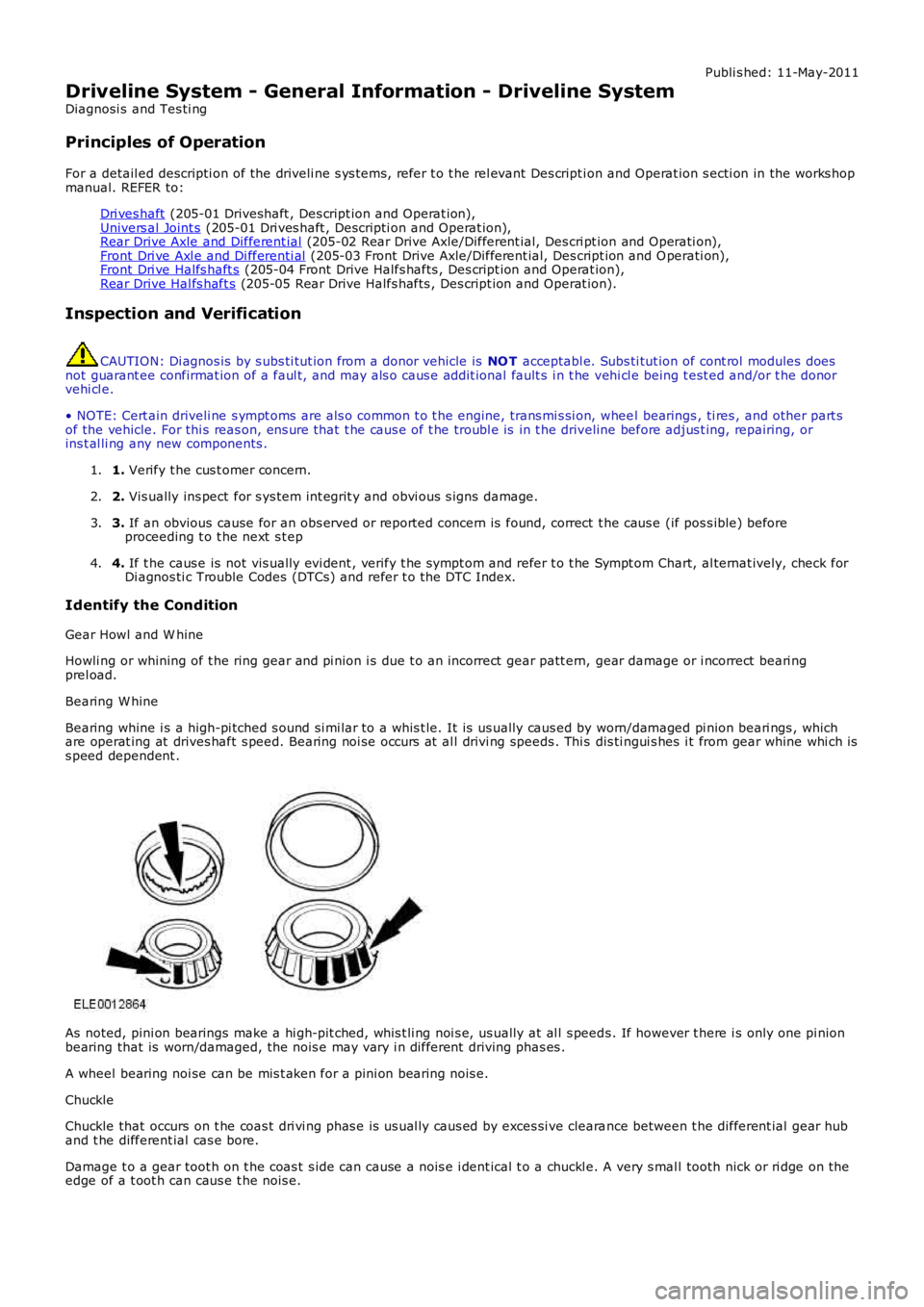
Bearing W hine
Bearing whine i s a high-pi tched s ound si mi lar to a whis t le. It is us ually caus ed by worn/damaged pi nion beari ngs , whichare operat ing at drives haft s peed. Bearing noi se occurs at al l drivi ng speeds . Thi s dis ti ngui s hes i t from gear whine whi ch iss peed dependent .
As noted, pini on bearings make a hi gh-pit ched, whis t li ng noi s e, us ually at al l s peeds . If however t here i s only one pi nionbearing that is worn/damaged, the nois e may vary i n different driving phas es .
A wheel bearing noi se can be mis t aken for a pini on bearing nois e.
Chuckle
Chuckle that occurs on t he coas t dri vi ng phas e is us ual ly caus ed by exces si ve clearance between t he different ial gear huband t he different ial cas e bore.
Damage t o a gear toot h on t he coas t s ide can cause a nois e i dent ical t o a chuckl e. A very s mal l tooth nick or ri dge on theedge of a t oot h can caus e t he nois e.