LAND ROVER FRELANDER 2 2006 Repair Manual
FRELANDER 2 2006
LAND ROVER
LAND ROVER
https://www.carmanualsonline.info/img/64/57251/w960_57251-0.png
LAND ROVER FRELANDER 2 2006 Repair Manual
Trending: tire type, fuel tank removal, automatic transmission, turn signal bulb, fuse box location, checking oil, transmission fluid
Page 931 of 3229
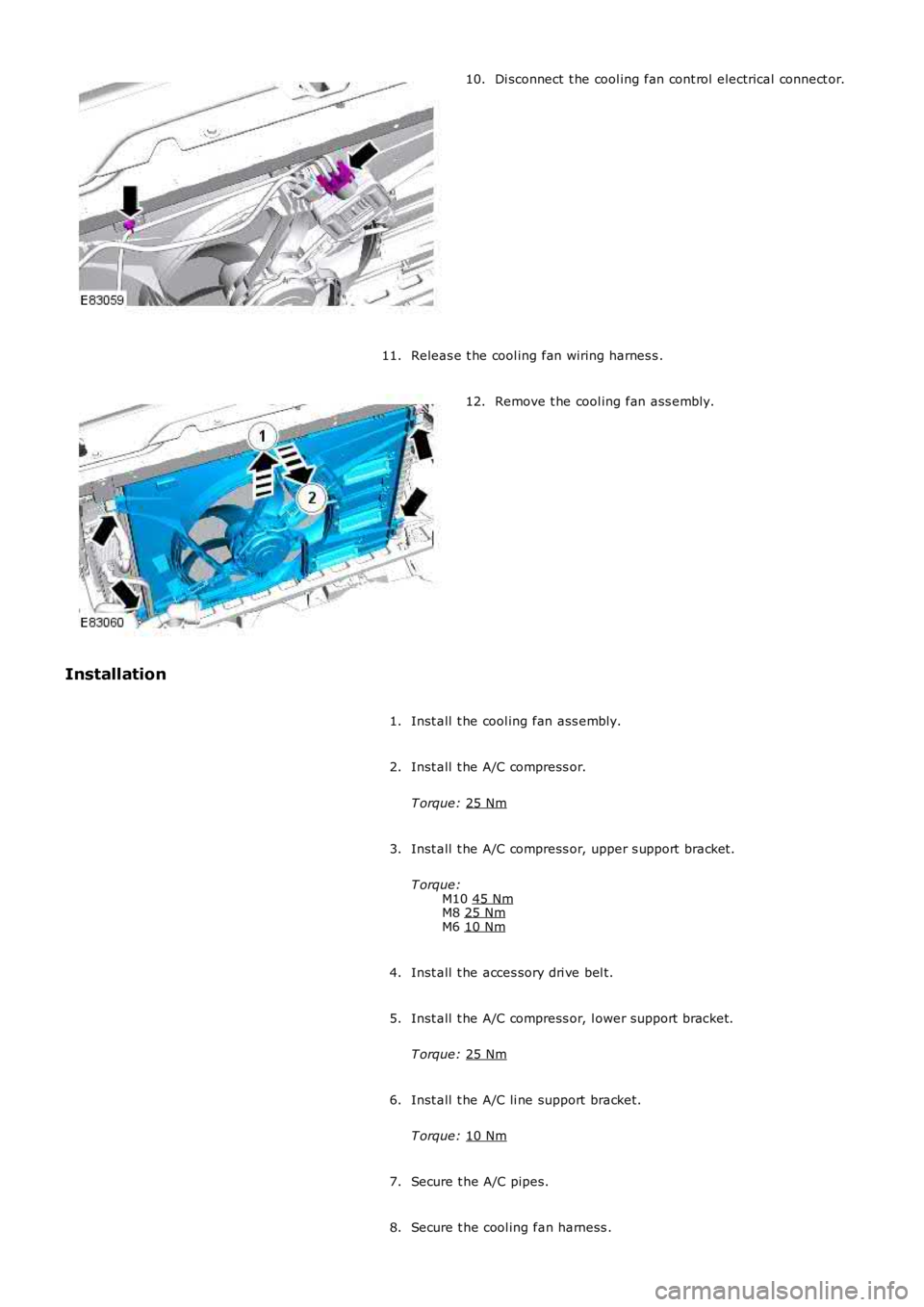
Di sconnect t he cool ing fan cont rol electrical connect or.
10.
Releas e t he cool ing fan wiring harnes s .
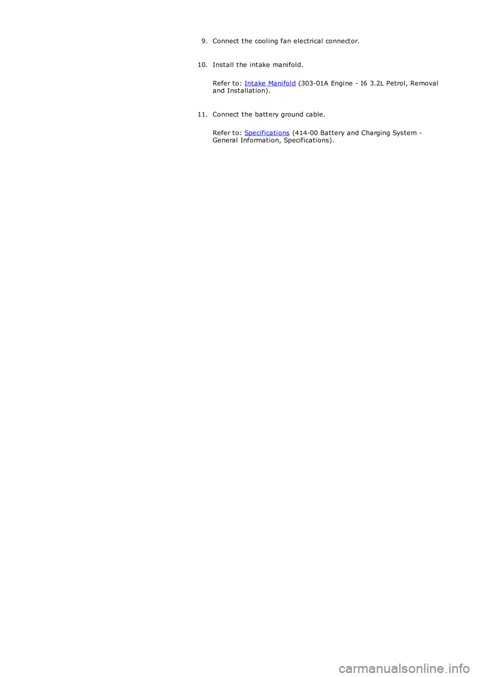
11. Remove t he cool ing fan ass embly.
12.
Installation Inst all t he cool ing fan ass embly.
1.
Inst all t he A/C compress or.
T orque: 25 Nm 2.
Inst all t he A/C compress or, upper s upport bracket.
T orque: M10 45 Nm M8
25 Nm M6
10 Nm 3.
Inst all t he acces sory dri ve bel t.
4.
Inst all t he A/C compress or, l ower support bracket.
T orque: 25 Nm 5.
Inst all t he A/C li ne support bracket.
T orque: 10 Nm 6.
Secure t he A/C pipes.
7.
Secure t he cool ing fan harness .
8.
Page 932 of 3229
Connect t he cool ing fan electrical connect or.
9.
Inst all t he int ake mani fol d.
Refer t o: Int ake Mani fol d (303-01A Engi ne - I6 3.2L Petrol, Removal
and Inst all at ion).
10.
Connect t he batt ery ground cable.
Refer t o: Specificati ons (414-00 Bat tery and Charging Sys tem -
General Informat ion, Specificati ons).
11.
Page 933 of 3229
Publi s hed: 11-May-2011
Engine Cooling - I6 3.2L Petrol - Cooling Fan Module
Removal and Inst all ati on
Removal
• NOTE: Petrol ill ust rat ion s hown, dies el s i mil ar.
Remove t he cover and dis connect the bat tery ground cabl e.
Refer t o: Specificati ons (414-00 Bat tery and Charging Sys tem -
General Informat ion, Specificati ons).
1.
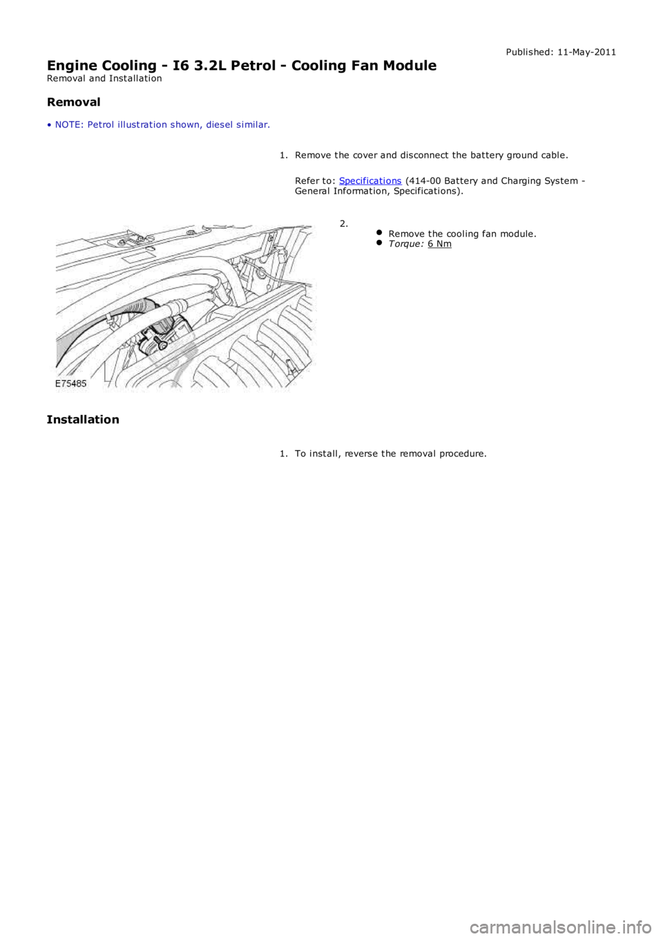
Remove t he cool ing fan module. T orque:
6 Nm 2.
Installation To i nst all , revers e t he removal procedure.
1.
Page 934 of 3229
Publi s hed: 11-May-2011
Engine Cooling - I6 3.2L Petrol - Coolant Expansion Tank
Removal and Inst all ati on
Removal W ARNING: W hen rel eas i ng the cooli ng s ys t em pres s ure, cover t he cool ant expansi on tan
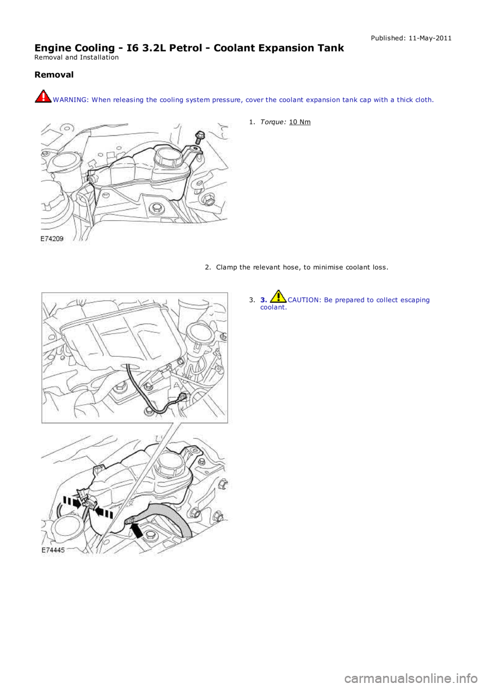
k cap wi th a t hi ck cl oth.T orque:
10 Nm 1.
Clamp the relevant hos e, t o mi ni mis e coolant los s .
2. 3. CAUTION: Be prepared to col lect escaping
cool ant.
3.
Page 935 of 3229
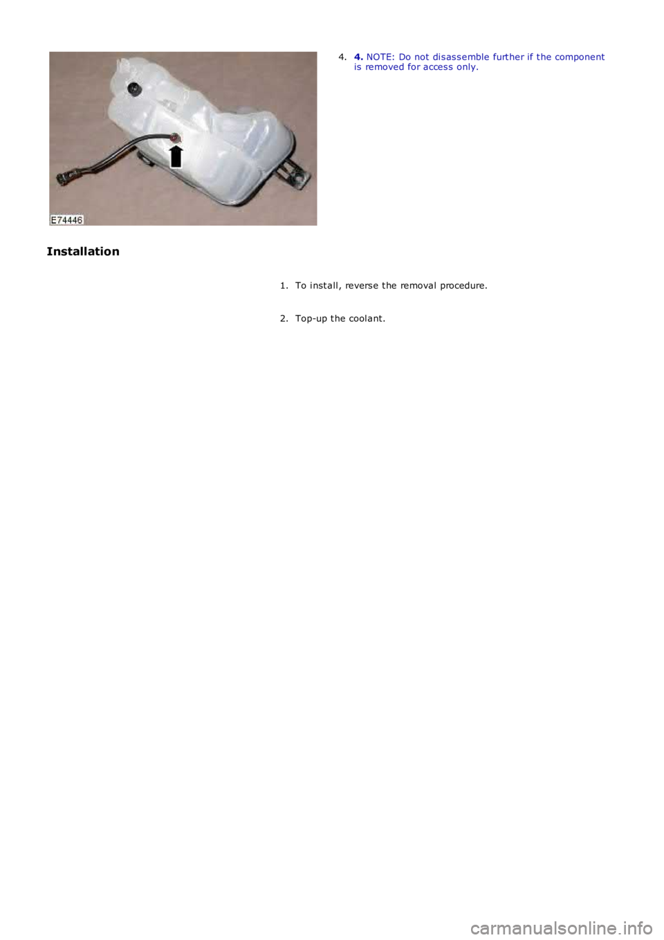
4. NOTE: Do not di s as s emble furt her if t he componentis removed for acces s only.4.
Installation
To i nst all , revers e t he removal procedure.1.
Top-up t he cool ant.2.
Page 936 of 3229
Publi s hed: 11-May-2011
Engine Cooling - I6 3.2L Petrol - Engine Coolant Level Switch
Removal and Inst all ati on
Removal
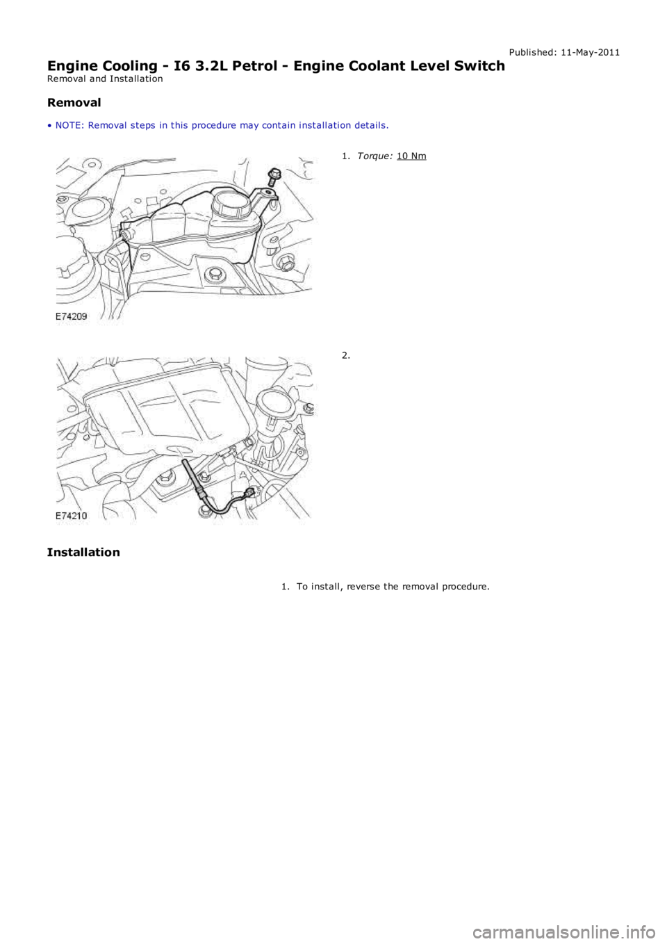
• NOTE: Removal s t eps in t his procedure may cont ain i nst all ati on det ail s. T orque:
10 Nm 1.
2.
Installation To i nst all , revers e t he removal procedure.
1.
Page 937 of 3229
Publi s hed: 11-May-2011
Engine Cooling - TD4 2.2L Diesel -
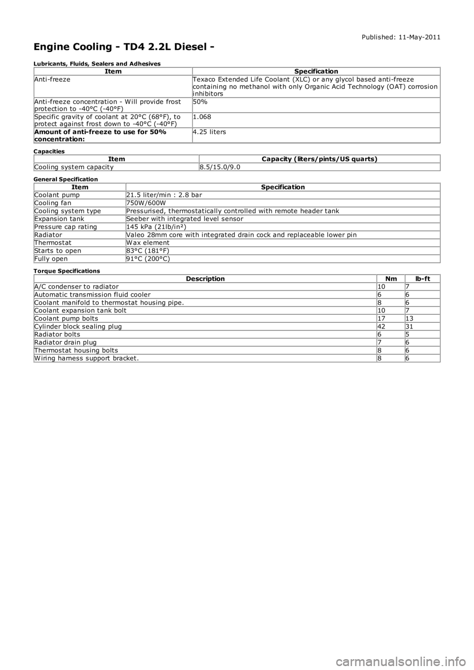
Lubricants, Fluids, Sealers and AdhesivesItemSpecification
Anti -freezeTexaco Ext ended Li fe Coolant (XLC) or any glycol bas ed anti -freezecontaini ng no met hanol wit h only Organic Acid Technology (O AT) corrosi oni nhi bit ors
Anti -freeze concentrati on - W i ll provi de frostprot ect ion to -40°C (-40°F)50%
Speci fi c gravit y of cool ant at 20°C (68°F), t oprot ect agains t fros t down to -40°C (-40°F)1.068
Amount of anti-freeze to use for 50%concentration:4.25 li ters
C apacitiesItemCapacity (liters/pints/US quarts)
Cooli ng sys t em capacit y8.5/15.0/9.0
General Specification
ItemSpecificationCoolant pump21.5 li ter/mi n : 2.8 bar
Cooli ng fan750W /600W
Cooli ng sys t em t ypePress uri s ed, t hermos tat icall y cont roll ed wi th remote header t ankExpans ion tankSeeber wit h int egrated level s ensor
Pres s ure cap rati ng145 kPa (21lb/i n²)
Radiat orVal eo 28mm core wit h i nt egrat ed drain cock and repl aceable l ower pi nThermos t atW ax element
St arts to open83°C (181°F)
Full y open91°C (200°C)
Torque Specifications
DescriptionNmlb-ftA/C condens er t o radiator107
Automat ic trans mi ss i on fl uid cooler66
Coolant manifold t o t hermos tat hous ing pipe.86Coolant expans ion t ank bol t107
Coolant pump bolt s1713
Cyli nder block s ealing pl ug4231Radiat or bolt s65
Radiat or drain pl ug76
Thermos t at hous ing bolt s86W iri ng harnes s s upport bracket .86
Page 938 of 3229
Publi s hed: 11-May-2011
Engine Cooling - TD4 2.2L Diesel - Engine Cooling
Des cript ion and Operat ion
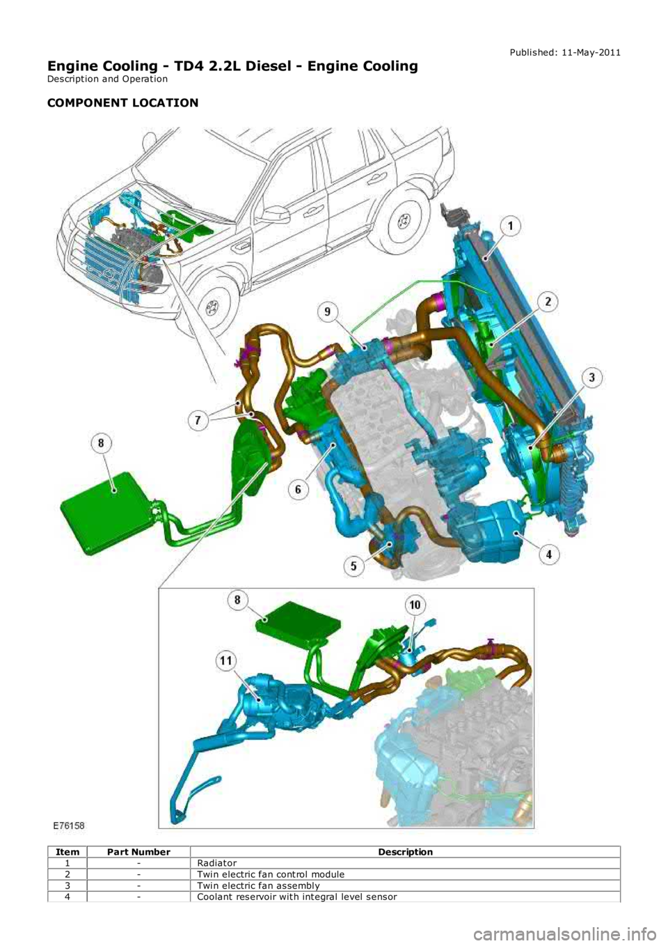
COMPONENT LOCATION
ItemPart NumberDescription1-Radiat or
2-Twi n electric fan cont rol module
3-Twi n electric fan as sembl y4-Coolant res ervoir wit h int egral level s ens or
Page 939 of 3229
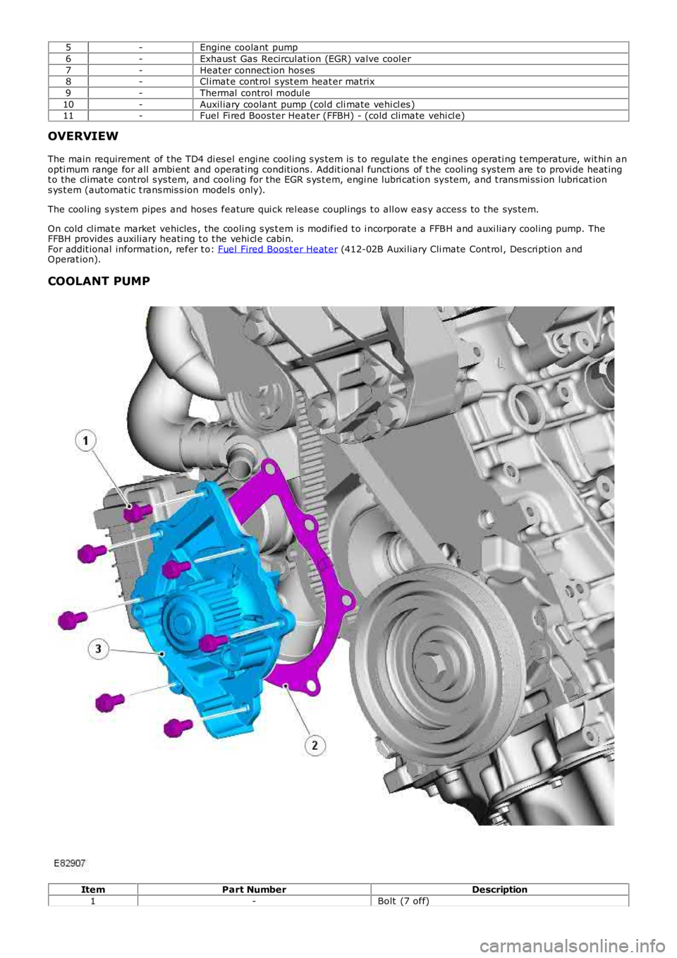
5-Engine coolant pump
6-Exhaus t Gas Recircul at ion (EGR) valve cool er
7-Heat er connect ion hos es8-Cl imat e cont rol s yst em heat er matrix
9-Thermal control modul e
10-Auxil iary coolant pump (col d cli mate vehi cl es )11-Fuel Fi red Boos ter Heater (FFBH) - (cold cli mate vehi cl e)
OVERVIEW
The main requirement of t he TD4 di es el engi ne cool ing s ys tem is t o regul ate t he engines operati ng t emperature, wit hi n anopti mum range for all ambi ent and operat ing condit ions. Addit ional functi ons of t he cool ing s ys tem are to provi de heat ingt o the cl imat e cont rol s ys tem, and cooling for the EGR s ys t em, engi ne lubri cat ion sys tem, and t rans mi ss i on lubri cat ions ys t em (automat ic t rans mis s ion model s only).
The cool ing s ys tem pipes and hoses feature qui ck rel eas e coupl ings t o all ow eas y acces s to the sys tem.
On cold cl imat e market vehicles , the cooli ng s ys t em i s modified t o i ncorporate a FFBH and auxi liary cool ing pump. TheFFBH provides auxili ary heati ng t o t he vehi cl e cabi n.For addit ional informat ion, refer t o: Fuel Fired Boost er Heat er (412-02B Auxi liary Cli mate Cont rol , Des cri pti on andOperat ion).
COOLANT PUMP
ItemPart NumberDescription
1-Bolt (7 off)
Page 940 of 3229
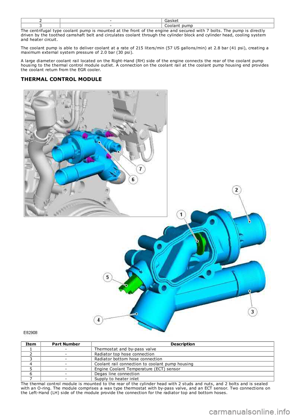
2-Gas ket
3-Coolant pump
The cent ri fugal type coolant pump is mount ed at t he front of t he engine and s ecured wit h 7 bol ts . The pump i s direct lydri ven by the t oothed cams haft belt and circul ates coolant through t he cylinder block and cyl inder head, cool ing s ys temand heat er circuit .
The cool ant pump is able to del iver cool ant at a rate of 215 lit ers /min (57 US gal lons /min) at 2.8 bar (41 psi ), creat ing amaximum external s yst em press ure of 2.0 bar (30 psi ).
A l arge di amet er cool ant rail located on the Ri ght -Hand (RH) s ide of t he engine connects the rear of t he coolant pumphous i ng to the t hermal control modul e outl et . A connect ion on t he cool ant rail at t he cool ant pump hous ing end provi dest he coolant return from t he EGR cooler.
THERMAL CONTROL MODULE
ItemPart NumberDescription
1-Thermos t at and by-pass val ve
2-Radiat or top hos e connecti on3-Radiat or bot tom hose connect ion
4-Coolant rai l connect ion to coolant pump hous ing
5-Engine Coolant Temperat ure (ECT) sens or6-Degas l ine connecti on
7-Supply t o heater i nl et
The t hermal cont rol module i s mounted to t he rear of t he cyl inder head wit h 2 s t uds and nut s , and 2 bolt s and is s ealedwit h an O-ring. The module compri s es a wax t ype thermos t at wit h by-pas s valve, and an ECT s ens or. Two connect ions ont he Left-Hand (LH) s i de of the module provide t he connecti on for t he radi at or top and bot tom hoses .
Trending: wheel size, reset, height, engine oil, CD player, radiator, fold seats
